Table of Contents
Advertisement
Quick Links
ISO Registered Company
I. DESCRIPTION AND SCOPE
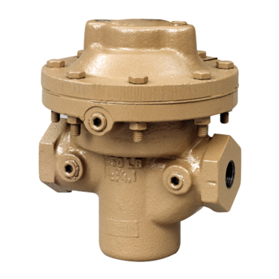
The Model DA6 is a pressure loaded back pressure regulator used to control upstream (inlet or P1) pressure. Sizes
are 1/2" (DN15), 3/4" (DN20), 1" (DN25), 1 1/4" (DN32), 1 1/2" (DN40), 2" (DN50), 3" (DN80) and 4" (DN100). With
proper trim uti li za tion, the unit is suitable for liquid, gaseous, or steam service. Typically installed in a more com-
mon "reverse" flow direction arrangement that is balanced (to outlet). Refer to Technical Bulletin DA6-TB for design
conditions and selection rec om men da tions. (NOTE: This product was formerly iden ti fied as a Model D6; a Model
DA6 and D6 are one and the same product.)
II. REFERENCES
Refer to Technical Bulletin DA6-TB and DAG-TB for
tech ni cal specifications of a Model DA6 regulator.
III. INSTALLATION
1. Install per direction of flow arrow indicated on
body, or "IN" and "OUT" markings.
2. Regulator may be rotated around pipe axis 360
degrees. For ease of maintenance, the rec om-
mend ed position is with the cover dome (25)
up wards. In liquid service it is recommended that
the cover dome (25) be oriented down wards, and
that a cus tom er supplied and installed vent valve
be pro vid ed at the external sensing connection
to bleed-off trapped gas/air under the diaphragm
during initial startup.
3. Provide space below, above, and around reg u la tor
for removal of parts during maintenance.
4. Install block valves and pressure gauges to pro-
vide means for adjustment, operation, bypass,
or removal of the regulator. A pipeline strainer
is recommended before inlet to remove typical
pipe line debris from entering valve and damaging
internal "soft goods", primarily the dynamic side
seal and V-TFE seat when applied.
5. Upstream Sensing Installation Considerations –
Internal or External Sensing:
a. The regulator may be installed with internal or
external sensing. Unless otherwise spec i fied,
INSTALLATION, OPERATION & MAINTENANCE MANUAL (IOM)
MODEL DA6
DA6 - DIRECT-ACTING, PRESSURE LOADED
BACK PRESSURE REGULATOR
SECTION I
SECTION II
CCW – Counter Clockwise
CW
ITA
SECTION III
the regulator is supplied by factory with internal
sensing. The regulator may be con vert ed in
the field to external sensing. (See Section VII
Maintenance, Part H – Converting Internal/
External Sensing.)
b. Reference DAG-TB, Table DAG-12 for rec om-
men da tions for applying external pressure
sensing.
c. For internal sensing, no external line is re-
quired. For external sensing, use an external
control line. The line is connected from the
port 1/4" (DN8) NPT tap (Port 5 – See Fig. 5)
on the side of the body di a phragm flange to a
pressure tap upstream of the regulator. Use
1/4" (6.4 mm) or 3/8" (9.5 mm) outer di am e ter
tubing or 3/8" (DN10) pipe having an inner
di am e ter equivalent to schedule 40 pipe.
d. For condensable vapors (i.e. steam) slope the
external sensing line downward 2 to 5 de grees
to inlet piping to prevent water pock ets, which
allows the diaphragm chamber to al ways be
self draining. The external sensing line may
be sloped upward for gas or liquid service; i.e.
non-condensibles.
Installation of adequate overpressure pro tec tion
is recommended to pro tect the reg u la tor from
over pres sure and all down stream equip ment from
dam age in the event of regulator failure.
ABBREVIATIONS
– Clockwise
– Inner Trim Assembly
CAUTION
IOM-DA6
12-16
Advertisement
Table of Contents

Related Manuals for cashco DA6


Summary of Contents for cashco DA6
- Page 1 I. DESCRIPTION AND SCOPE The Model DA6 is a pressure loaded back pressure regulator used to control upstream (inlet or P1) pressure. Sizes are 1/2" (DN15), 3/4" (DN20), 1" (DN25), 1 1/4" (DN32), 1 1/2" (DN40), 2" (DN50), 3" (DN80) and 4" (DN100). With proper trim uti li za tion, the unit is suitable for liquid, gaseous, or steam service.
-
Page 2: Principle Of Operation
CAU TION DO NOT HYDROSTATIC TEST THROUGH AN IN STALLED UNIT; ISOLATE REGULATOR FROM TEST. See Technical Bulletin DA6-TB, Table 1; Maximum P - Inlet Pressure levels for various diaphragm materials by valve body size. Higher pres sures could cause in ter nal dam age. The name- plate indicates the Inlet and Outlet pres sure and tem per a ture ratings. -
Page 3: Maintenance
27 ..... All ......Dynamic Side Seal * parts. Only use original equip ment parts sup- 27.1 ....CP ........TFE Cap Seal plied by Cashco for re build ing or re pair ing 27.2 ....CP ......O-ring Energizer/Seal regulators. 27.3 ....UC ..U-Cup Seal w/Metal Energizer 27.5 ....PR ......... - Page 4 NOTE: Two separate piston rings per assembly. Type CP— TFE Cap Dynamic Seal Type PR — PRA Dynamic Seal Type NO — No Dynamic Seal Type UC — U-Cup Dynamic Seal Figure 1: Dynamic Side Seals IOM-DA6...
- Page 5 Remove diaphragm(s) (9, 9.1, 9.2, 9.9). phragm flange. Examine diaphragm(s) to determine wheth er failed; determine if operating 14. Remove body (23) from vise. Solvent clean con di tions are ex ceed ing pressure drop all removed metal parts. or temperature limits. IOM-DA6...
- Page 6 Rework and clean drop, or temperature lim its. IOM-DA6...
- Page 7 2. Spread a piston ring seal (27.5) and pointed up wards. slide over lower circumference groove b. Using a torque wrench, tighten the seat of valve plug (20), taking care not to disc nut (30) to 20 – 35 ft-lbs. by rotating IOM-DA6...
- Page 8 3/4" hex, use another wrench to tighten Place new o-ring middle stem seal (14.2) into diaphragm locknut (7) to a torque of 180- groove of valve plug (20) upper surface. 200 ft-lbs. 10. Position lower diaphragm pusher plate (10) IOM-DA6...
- Page 9 11. Evenly tighten the body bolting (11,12) in an (19), simultaneously use fingers to lightly alternating cross pattern in one revolution circumferentially press the first (low er) increments to the following torque value: piston ring seal (27.5) inwards into the IOM-DA6...
- Page 10 Cover dome (25) is specially machined to provide a surface for the upper di a phragm 3. Pressure Containment Test. (9) support. a. Pressurize inlet, outlet and cover dome c. When disassembling valve unit, after low er to 150 psig with air or GN IOM-DA6...
-
Page 11: Section Viii
The key to efficient trouble shooting is information and communication. The customer should try to be as precise as possible in their explanation of the problem, as well as their understanding of the ap pli ca tion and operating con di tions. IOM-DA6... - Page 12 C. Pressure loading system pressure C1. Clean restriction or bleed orifices. restricted. C2. Clean filter(s). C3. Clean loading pressure control device. D. Faulty loading pressure control device. D. Replace/repair loading pressure control device. IOM-DA6...
- Page 13 Install pressure safety equipment as necessary. (See Table 1 in Tech Bulletin A2. Consider if full diaphragm support, Opt-81, should be added. DA6-TB.) Leakage at diaphragm flange. Possible Causes Remedies A. Body bolts not torqued properly.
-
Page 14: New Replacement Unit
(last digit is alpha character that reflects revision level for the product). – – NEW REPLACEMENT UNIT: Contact your local Cashco, Inc., Sales Rep re sen- ta tive with the Serial Number and Product code. With this information they can provide a quotation for a new unit including a complete description, price and availability. - Page 15 Cashco, Inc. does not assume responsibility for the selection, use or maintenance of any product. Responsibility for proper selection, use and maintenance of any Cashco, Inc.
- Page 16 Model DA6 Metal Diaphragm FTC – Standard Flow Direction Item No. Description Item No. Description Lower Guide Bushing Diaphragm Lock Nut Cover Dome Upper Diaphragm Pressure Plate Tap Plug 9 ‡‡ Diaphragm 27 ‡‡ Dynamic Side Seal Diaphragm (Material #1) 27.1...
- Page 17 ATEX requires that all components and equipment be evaluated. Cashco pressure regulators are considered components. Based on the ATEX Directive, Cashco considers the location where the pressure regulators are installed to be classified Equipment-group II, Category 3 because flammable gases would only be present for a short period of time in the event of a leak.
- Page 18 If the above issues are addressed by selecting options that do not have potential sources of ignition, avoiding options that have not been assessed, and by taking the proper usage issue precautions, then Cashco regulators can be considered to be a mechanical device that does not have its own source of ignition and thus falls outside the scope of the ATEX directive.
Need help?
Do you have a question about the DA6 and is the answer not in the manual?
Questions and answers