Advertisement
ISO Registered Company
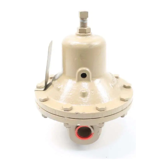
PRESSURE REDUCING REGULATORS
I. DESCRIPTION AND SCOPE
The Model D is a pressure reducing regulator used to control downstream (outlet or P
1/2" (DN15), 3/4" (DN20) and 1" (DN25). With proper trim utilization, the unit is suit able for liquid, gase ous, or steam
serv ice. Refer to Technical Bulletin D-TB for design conditions and se lec tion recommendations.
The Model DL is also a pressure reducing regulator similar to above Model D. Sizes are 1-1/2" (DN40) and 2" (DN50).
(Model DL was formerly a Cashco Model D). Refer to Technical Bulletin DL-TB for design conditions and selection
recommendations.
II. INSTALLATION
For welded installations, all internal trim parts, seals
and diaphragm(s) must be removed from regulator
body prior to welding into pipeline. The heat of
fusion welding will damage non-metallic parts if
not removed. NOTE: This does not apply to units
equipped with extended pipe nipples.
1.
An inlet block valve should always be in stalled.
2.
If service application is continuous such that
shut down is not readily accomplished, it is rec-
ommended that an inlet block valve, outlet block
valve, and a manual bypass valve be installed.
3.
Pipe unions should be installed to allow re moval
from piping, if flanges are not being used.
4.
An outlet pressure gauge should be located
ap prox i mate ly ten pipe diameters downstream and
within sight.
5.
All installations should include a downstream
re lief device if the inlet pressure could exceed the
pres sure rating of any downstream equip ment or the
maximum outlet pressure rating of the unit.
Installation of adequate overpressure pro tec tion
is recommended to pro tect the reg u la tor from
overpressure and all down stream equip ment from
damage in the event of regulator failure.
INSTALLATION, OPERATION & MAINTENANCE MANUAL (IOM)
MODELS D and DL
CAUTION
CAUTION
SECTION I
SECTION II
Supply
@ P1
Blowdown-Drain
(Shaded portion for steam/condensate systems)
Recommended Piping Schematic
6.
Clean the piping of all foreign material in clud ing
chips, welding scale, oil, grease and dirt be fore
installing the regulator. Strainers are rec om mend ed.
7.
If placing thread sealant on pipe ends prior to
en gage ment, ensure that excess material is
re moved and not allowed to enter the regu la tor upon
startup.
8.
Flow Direction: Install so the flow direction match es
the arrow on the body.
9.
For best performance, install in well drained
hori zon tal pipe, properly trapped, if a steam service
application.
10.A. Basic Regulator - (Refer to Figure 2): Regu la tor
may be rotated around the pipe axis 360
om mended position is with spring cham ber ver ti cal
upwards. Ori ent such that the spring cham ber vent
hole does not collect rainwater or debris.
) pressure. Sizes are 3/8" (DN10),
2
Model D or DL
Reducing
Regulator
For Pressure Reducing Station
IOM-D/DL
01-22
Outlet
@ P2
SRV
Bypass
Blowdown-Drain
. Rec-
o
Advertisement
Table of Contents

Related Manuals for cashco D


Summary of Contents for cashco D
- Page 1 Refer to Technical Bulletin D-TB for design conditions and se lec tion recommendations. The Model DL is also a pressure reducing regulator similar to above Model D. Sizes are 1-1/2" (DN40) and 2" (DN50). (Model DL was formerly a Cashco Model D). Refer to Technical Bulletin DL-TB for design conditions and selection recommendations.
-
Page 2: Principle Of Operation
13. Spring Chamber Vent Tap - Pipe spring chamber vent opening to remote lo ca tion. Orient so as not to 10.B. Model D Cryogenic Regulator - Option D-5 or D-36 take on rainwater. SECTION III III. -
Page 3: Maintenance
“cleaned for Phar ma ceu ti cal and flange bolts, relieve spring com pres sion by backing Food ap pli ca tions” Op tion D-37 or D-37S, out the ad just ing screw. Failure to do so may result main te nance must in clude a level of cleanliness in flying parts that could cause personal injury. - Page 4 (4) where adjusting screw (6) bears. Set NOTE: On regulators originally supplied as spring button onto top of range spring; ensure “oxygen clean”, Option D-5 , D-36, D-55, or spring button is laying flat. DL-55, maintenance must include a level of clean li ness equal to Cashco cleaning 11.
-
Page 5: Troubleshooting Guide
Can be caused by excessive chattering. See No. 1. to remedy chatter. Can be caused by corrosive action. Consider alternate diaphragm material. For composition diaphragms, ensure not subjecting to over-temperature conditions. Downstream (outlet) pressure buildup occurring that overstresses diaphragms. Relocate regulator or protect with safety relief valve. IOM-D/DL... -
Page 6: Section Viii
Cashco, Inc. does not assume responsibility for the selection, use or maintenance of any product. Responsibility for proper selection, use and maintenance of any Cashco, Inc. product remains solely with the purchaser. - Page 7 Figure 1: Option-4 - Stabilizer Figure 2: Basic Model D - Comp Diaphragm Figure 3: Flow Arrow SPARE PART ITEM GENERAL DESCRIPTION BODY SPRING CHAMBER PRESSURE PLATE SPRING BUTTON BODY CAP ADJUSTING SCREW HEX JAM NUT HEX HEAD CAP SCREW...
- Page 8 MODEL DL Figure 6: Option D-3 or DL-3 Handwheel and Locking Lever SPARE PART ITEM GENERAL DESCRIPTION BODY SPRING CHAMBER PRESSURE PLATE SPRING BUTTON BODY CAP ADJUSTING SCREW HEX JAM NUT HEX HEAD CAP SCREW NAMEPLATE PUSHER PLATE DIAPHRAGM DIAPHRAGM GASKET...
- Page 9 ATEX 2014/34/EU: Explosive Atmospheres and Cashco Inc. Products Cashco, Inc. declares that the products listed in the table below has been found to comply with the Essential Health and Safety Requirements relating to the design and construction of products intended for use in potentially explosive atmospheres given in Annex II of the ATEX Directive 2014/34/EU.
- Page 10 1000HP-1+6, 1000HP-1+8, 1000LP, 1000LP(OPT-45), 1000LP(OPT-46G) 6987 8310HP, 8310HP-1+6, 8310HP-1+8, 8310LP, 8311HP, 8311LP 345, 345(OPT-45) BA1/BL1, PA1/PL1 C-BPV, C-PRV, C-CS D, D(CRYO), D(OPT-37), D(OPT-20), D(OPT-45) DL, DL(LCC), DL(OPT-45) BR, BR(CRYO) HP, HP(LCC), HP(OPT-45), HP(OPT46G), HP-1+6+S(OPT-40), HP-1+6+S P1, P2, P3, P4, P5, P7 B2, B7...
Need help?
Do you have a question about the D and is the answer not in the manual?
Questions and answers