Advertisement
ISO Registered Company
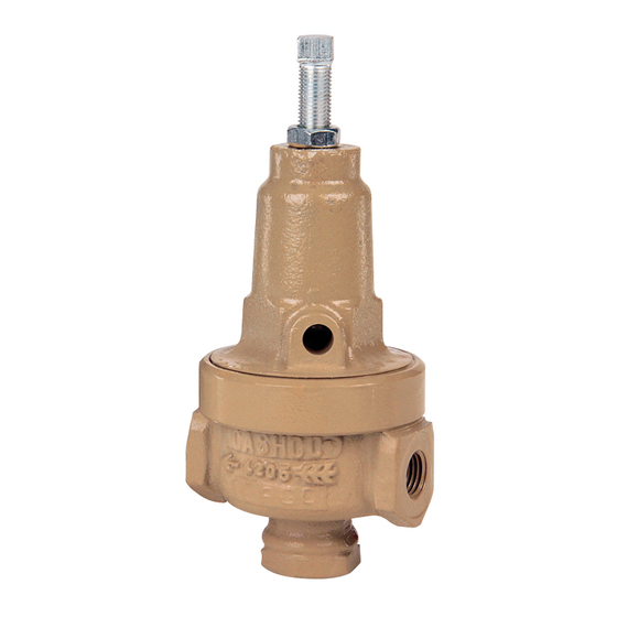
I. DESCRIPTION AND SCOPE
Models 3381 and 4381 are pressure reducing regulators used to control downstream (outlet or P
Sizes are 1/4" and 3/8" (DN8 and DN10) for the 3381. Sizes for the 4381 are 1/4", 3/8", and 1/2" (DN8, DN10,
and DN15). The 3381 is a bronze bodied unit; the 4381 incorporates a stainless steel body. With proper trim
utili za tion, both units are suitable for liquid, gaseous and steam service (the 4381 can also be used with various
chemi cals). Refer to Tech ni cal Bul le tins 3381-TB and 4381-TB for specific design conditions and selection
rec om men da tions.
The instructions in this manual will apply to both models, unless otherwise stated.
II. INSTALLATION
For welded installations, all internal trim parts, seals and
diaphragm(s) must be removed from reg u la tor body prior
to welding into pipeline. The heat of fusion welding will
dam age non-metallic parts if not re moved. NOTE: This
does not apply to units equipped with extended pipe
nip ples.
Option-1+6 contains single di a phragm con struc tion. In
the event of diaphragm fail ure, the process flu id will mix
with the load ing fluid. Please alert your rep re sen ta tive so
an al ter na tive product can be se lect ed.
1. An inlet block valve should always be installed.
2. If service application is continuous such that
shut down is not readily accomplished, it is rec-
ommended that an inlet block valve, outlet block
valve, and a manual bypass valve be installed.
3. Pipe unions should be installed to allow removal
from piping.
4. An outlet pressure gauge should be located
ap proxi mately ten pipe diameters downstream,
and within sight.
5. All installations should include a downstream
re lief de vice if the inlet pressure could exceed the
pres sure rating of any downstream equip ment or
the maximum outlet pressure rating of the unit.
6. Clean the pip ing of all foreign material including
chips, welding scale, oil, grease and dirt
INSTALLATION, OPERATION & MAINTENANCE MANUAL (IOM)
MODELS 3381 AND 4381
PRESSURE RE DUC ING REGULATORS
CAUTION
CAUTION
SECTION I
SECTION II
Installation of adequate overpressure pro tec tion is
recommended to pro tect the reg u la tor from overpressure
and all down stream equip ment from damage in the event
of regulator failure.
before installing the reg u la tor.
rec om mend ed.
7. In plac ing thread seal ant on pipe ends pri or to
en gage ment, ensure that excess material is
re moved and not allowed to enter the regulator
upon startup.
8. Flow Direction: Install so the flow direction
match es the arrow cast on the main regulator
body.
9. For best performance, install in well drained
hori zon tal pipe, properly trapped if a steam
service ap pli ca tion.
IOM-3381/4381
) pressure.
2
CAUTION
Strainers are
06-17
Advertisement
Table of Contents

Related Manuals for cashco 3381


Summary of Contents for cashco 3381
- Page 1 ) pressure. Sizes are 1/4" and 3/8" (DN8 and DN10) for the 3381. Sizes for the 4381 are 1/4", 3/8", and 1/2" (DN8, DN10, and DN15). The 3381 is a bronze bodied unit; the 4381 incorporates a stainless steel body. With proper trim utili za tion, both units are suitable for liquid, gaseous and steam service (the 4381 can also be used with various chemi cals).
-
Page 2: Principle Of Operation
10 A. Basic Regulator - (Refer to Figure 1, Model 3381 ver ti cal down wards orientation. Allows water or 4381): Regulator may be rotated around the to drain; etc. pipe axis 360°. Recommended position is with b. Recommend inert purge gas be supplied to spring chamber vertical upwards. -
Page 3: Maintenance
6. Loosen pusher plate nut (10) and separate all parts (3, 4, 9, 13 & 15) of the diaphragm 3. Refer to Figure 1, Model 3381 or 4381 for the subassembly. basic regulator and Figure 2, Model 3381 or 4381 for the cryo gen ic regulator. - Page 4 4381-37S, maintenance must include a D. Special Instructions for Diaphragm Removal: level of clean li ness equal to Cashco cleaning stan dard #S-1576. Con tact fac to ry for details. 1. If the TFE coated diaphragm (13) is utilized on the Model 4381, the TFE coating is the wetted 10.
-
Page 5: Troubleshooting Guide
3381-5 & -55, 4381-36 two parts seal metal-to-metal with no gasket. & 55 main te nance must in clude a level of clean li ness equal to Cashco's clean ing stan- 10. Bench test unit for suitable operation. NOTE: dard #S-1134. -
Page 6: Section Viii
Cashco, Inc. does not assume responsibility for the selection, use or maintenance of any product. Responsibility for proper selection, use and maintenance of any Cashco, Inc. - Page 7 MODEL 3381 Figure 1: Basic Model 3381 with Metal Seat Design Figure 2: Option-5 Cryogenic Model 3381, Metal Seat Design (NOTE: Mount in Horizontal line with Adjusting Screw down as shown.) Composition Seat Design Repair Parts Item No. Description Kit B...
- Page 8 Diaphragm ------------------- ‡‡ Diaphragm Gasket --------- ‡‡ Pusher Plate Seal ---------- ‡‡ Piston ------------------------- ‡‡ Range Spring Handwheel Mounting Nut Thrust Bearing Upper Bearing Lower Bearing U-Cup ------------------------- ‡‡ Composition Seat with Option -4 Stabilizer Option-80, High Pressure Spring Chamber Construction IOM-3381/4381...
- Page 9 ATEX Essential Health and Safety Requirements, are listed below. The plastic knob used as standard on some models, (P1, P2, P3, P4, P5, P7, 3381, 4381, 1171, and 2171) is a potential ignition source due to static electricity. To demonstrate otherwise, the knob must be tested to determine if a transferred charge is below the acceptable values in IEC 60079-0 Section 26.14 (See items 25, 27, and 28 in...
- Page 10 If the above issues are addressed by selecting options that do not have potential sources of ignition, avoiding options that have not been assessed, and by taking the proper usage issue precautions, then Cashco regulators can be considered to be a mechanical device that does not have its own source of ignition and thus falls outside the scope of the ATEX directive.
Need help?
Do you have a question about the 3381 and is the answer not in the manual?
Questions and answers