Advertisement
Quick Links
ISO Registered Company
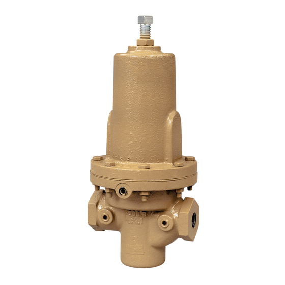
DIRECT-ACTING, POSITIVE BIAS DIFFERENTIAL
I. DESCRIPTION AND SCOPE
The Model DA8 is a differential back pressure regulator used to control differential pressure between the upstream
(inlet or P1) pressure and a loading (PLoad) pressure to the spring chamber. Available in sizes 1/2" (DN15), 3/4"
(DN20), 1" (DN25), 1-1/4" (DN32), 1-1/2" (DN40), 2" (DN50), 2-1/2" (DN65), 3" (DN80) and 4" (DN100). With proper
trim uti li za tion, the unit is suitable for liquid, gaseous, or steam service. Model DA8 is assembled in the "reverse"
flow direction arrangement that is balanced (to outlet).
II. REFERENCES
Refer to Technical Bulletin DA8-TB for tech ni cal
specifications.
III. INSTALLATION
For welded installations, all internal trim parts, seals
and diaphragm(s) must be removed from reg u la-
tor body prior to welding into pipeline. The heat of
fusion welding will dam age non-metallic parts if
not re moved. NOTE: This does not apply to units
equipped with extended pipe nip ples.
1. Regulator may be rotated around pipe axis 360
degrees. For ease of maintenance, the recom-
mended position is with the spring chamber (4)
upwards. In liquid service it is recommended that
the spring cham ber (4) be oriented downwards, and
that a cus tom er supplied and installed vent valve
be pro vid ed at the external sensing con nec tion to
bleed-off trapped gas/air under the di a phragm.
2. Provide space below, above, and around reg u la tor
for removal of parts during maintenance.
3. Install block valves and pressure gauges to pro-
vide means for adjustment, operation, bypass, or
removal of the regulator. An isolation valve on the
loading line is not rec om mend ed.
INSTALLATION, OPERATION & MAINTENANCE MANUAL (IOM)
MODEL DA8
(Formerly DA8/9)
BACK PRESSURE REGULATOR
CAUTION
SECTION I
SECTION II
CCW – Counter Clockwise
CW
ITA
SECTION III
4. An inlet pressure gauge should be located ap-
prox i mate ly ten pipe diameters upstream, and
within sight. A loading pressure (or differential
pressure) gauge is rec om mend ed.
5. Clean the piping of all foreign material including
chips, welding scale, oil, grease and dirt before in-
stall ing the regulator. Strainers are rec om mend ed.
6. In placing thread sealant on pipe ends prior to
en gage ment, ensure that excess material is re-
moved and not allowed to enter the regulator upon
startup.
7. Flow Direction: Install so the flow direction match es
the arrow cast on the body or other markings such
as "in" and "out".
8. Precaution for Standard Diaphragm Construction:
The loading pressure should be lowered sufficiently
prior to shutting off the process fluid supply, to pre-
vent change to the diaphragm. Startup, shutdown,
and emergency operating procedures should be
reviewed to ensure that the loading pressure is
less than 50% of the Diaphragm Proof Rating (See
ABBREVIATIONS
– Clockwise
– Inner Trim Assembly
IOM-DA8
01-17
Advertisement

Related Manuals for cashco DA8


Summary of Contents for cashco DA8
- Page 1 (DN20), 1" (DN25), 1-1/4" (DN32), 1-1/2" (DN40), 2" (DN50), 2-1/2" (DN65), 3" (DN80) and 4" (DN100). With proper trim uti li za tion, the unit is suitable for liquid, gaseous, or steam service. Model DA8 is assembled in the “reverse”...
- Page 2 Rating shown on the nameplate. For example, a the regulator is supplied by factory with internal 1" DA8 with Cast Iron Body and Spring Chamber, Neo- sensing. The regulator may be con vert ed in prene Diaphragm (BC) has an Inlet Pressure Rating of the field to external sensing (see Section VII 400 psig CWP.
-
Page 3: Principle Of Operation
The positive differential setting of the range the valve seat to maintain the inlet pressure (P spring for the DA8 tends to close the valve plug equal to the sum of the differential pressure (∆P against the valve seat. -
Page 4: Maintenance
27.6 ....PR ..Piston Ring Seal w/Metal Energizer parts. Only use original equipment parts sup- 28 ..... All ..........Seat Disc plied by Cashco for re build ing or re pair ing 29 ..... All ....... Seat Disc Washer regulators. 30 ..... All ........Seat Disc Nut * Possible option isType NO Dynamic Side Seal for standard flow only.. - Page 5 NOTE: Two separate piston rings per assembly. Type CP— TFE Cap Dynamic Seal Type PR — PRA Dynamic Seal Type UC — U-Cup Dynamic Seal Type NO — No Dynamic Seal (1-1/4"-2" Sizes) (Standard Flow Only) Figure 1: Dynamic Side Seals IOM-DA8...
- Page 6 3/4" hex upper end of plug (20). Loos en o-ring (15). diaphragm lock nut (7) while holding plug (20) from ro tat ing by socket wrench. 12. Remove lower cage gasket (21). Re move di a phragm lock nut (7) after fully IOM-DA8...
- Page 7 Surface con di tions that affect the regulator performance are stated 5. Body Sizes 2-1/2" through 4": below; replace parts that can not be re worked a. Orient plug (20) with threaded end up- or cleaned. IOM-DA8...
- Page 8 Pres sure to pres sure ac ti vate the seal (19). While gently applying force to for prop er seal ing ac tion. press the piston-guide bushing (13) or valve plug (20) into the cage (19), IOM-DA8...
- Page 9 (14.4) on/over upper end of valve plug (20) and onto 4. Position properly oriented lower cage gasket lower diaphragm pusher plate (10). (Gasket (21) onto lower shelf of cage (19). sealant is Federal Process Corp. “Gasoila” , or equal.) IOM-DA8...
- Page 10 Assembly of range spring and spring chamber adjusting screw CW until the adjusting for DA8: screw is fully fitted into the spring cham- a. Lubricate the threads of adjusting screw ber. DO NOT allow the spring chamber (1) then thread into the spring follower (5).
- Page 11 NOTE: for sizes 2" and smaller. This valve is NOT a bubble-tight shutoff de- vice. See DA8-TB, Table DAG-10 for leak age H. Converting Internal/External Sensing: classes. 1. Disassemble the regulator and remove the diaphragm(s) (9) according to Steps 1-12 in Part B –...
-
Page 12: Section Viii
Section VII, paragraph F-9. 5. Diaphragm continually breaks (all regulators). Possible Causes Remedies A. Differential pressure across diaphragm may have A. Reference limits as recorded in technical bulletin DA8-TB, as exceeded limits. well as where the various pressures are acting. IOM-DA8... -
Page 13: Parts Ordering Information
Step 1. Determine all available information from regu la- tor's metal tag. a. Serial number (5-digit). b. Regulator “Type” or “Model” number. c. Size (may have to observe body tap). d. Spring range. e. Trim designation number (if available). IOM-DA8... - Page 14 Figure 2 Composition Diaphragm FTO – Reverse Flow Direction IOM-DA8...
- Page 15 Internal Sensing Drilled Plug (Internal Sensing Only) 14.2 Middle Stem Seal 15 ‡‡ Cage Seal 34 ‡‡ Adjusting Screw O-Ring (Qty=2) Cage Cap Screws Nameplate (Not Shown) ‡‡ Recommended Repair Parts Figure 3 Metal Diaphragm FTO – Reverse Flow Direction IOM-DA8...
- Page 16 Cashco, Inc. does not assume responsibility for the selection, use or maintenance of any product. Responsibility for proper selection, use and maintenance of any Cashco, Inc. product remains solely with the purchaser.
- Page 17 ATEX requires that all components and equipment be evaluated. Cashco pressure regulators are considered components. Based on the ATEX Directive, Cashco considers the location where the pressure regulators are installed to be classified Equipment-group II, Category 3 because flammable gases would only be present for a short period of time in the event of a leak.
- Page 18 If the above issues are addressed by selecting options that do not have potential sources of ignition, avoiding options that have not been assessed, and by taking the proper usage issue precautions, then Cashco regulators can be considered to be a mechanical device that does not have its own source of ignition and thus falls outside the scope of the ATEX directive.
Need help?
Do you have a question about the DA8 and is the answer not in the manual?
Questions and answers