Sign In
Upload
Manuals
Brands
Vanguard Instruments Manuals
Measuring Instruments
DigiTMR S2
Vanguard Instruments DigiTMR S2 Manuals
Manuals and User Guides for Vanguard Instruments DigiTMR S2. We have
1
Vanguard Instruments DigiTMR S2 manual available for free PDF download: User Manual
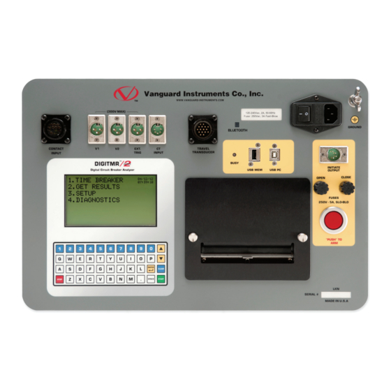
Vanguard Instruments DigiTMR S2 User Manual (123 pages)
DIGITAL CIRCUIT BREAKER ANALYZER
Brand:
Vanguard Instruments
| Category:
Measuring Instruments
| Size: 29 MB
Table of Contents
Table of Contents
3
Conventions Used in this Document
6
1 Introduction
7
General Description and Features
7
Operational Modes
10
On-Line" Mode
10
Time-Versus-Travel Circuit Breaker Analyzer Mode
10
Technical Specifications
11
Table 1. Digitmr S2 Technical Specifications
11
Digitmr S2 Controls and Indicators
12
Figure 1. Digitmr S2 Controls and Indicators
12
2 Pre-Test Setup
13
Operating Voltages
13
LCD Screen Contrast Control
13
Printer Paper Control
13
Printer Paper
13
3 Operating Procedures
15
Configuring the VCBA S2 Software for Use with the Digitmr S2
15
Connecting the Digitmr S2 to a PC Via Bluetooth
17
Digitmr S2 Cable Connections
25
Contact Cable Connections
25
Figure 2. Contact Cable Connections
25
Initiate Cable Connections
26
Figure 3. DC Trip and DC Close Initiate Circuit Cable Connections
26
Figure 4. DC Trip and AC Close Initiate Circuit Cable Connections
27
Analog and Digital Voltage Monitor Connections
28
Figure 5. Analog and Digital Voltage Monitoring Cable Connections
28
Figure 6. External Trigger Cable Connection for an Open Connection
29
Figure 7. External Trigger on a Close Operation Less 52Y Delay Time
30
AC Current Sensor Connection
31
Figure 8. Typical CT Connection
31
Transducer Connections
32
Figure 9. Typical Transducer Connection
32
Figure 10. Typical Resistor Type Transducer Connection
33
Figure 11. Vanguard Resistor Transducer Adapter Connected to an ABB AHMB Transducer
33
Figure 12. Vanguard Doble Transducer Adapter Connected to a Doble Linear Transducer
34
Figure 13. Vanguard Doble Transducer Adapter Connected to a Doble Rotary Transducer
34
General Procedures and Configuration
35
Figure 14. Digitmr S2 General Operating Procedures
35
Setting the Interface Language
36
Setting the Measurement Units
38
Setting the Digitmr S2'S Internal Clock
41
Entering Test Record Header Information
43
Setting the Frequency
46
Setting the Default Printing Mode
48
Timing Breakers in On-Line Mode
50
Timing Breakers in Time-Travel Mode
50
Performing Timing Tests
51
Timing an OPEN Operation with no Insertion Resistors
51
Timing an OPEN Operation with Insertion Resistors
55
Timing a CLOSE-OPEN Operation Using Contact Channel #1
58
Timing an OPEN-CLOSE-OPEN Operation
61
Performing Diagnostic Tests
64
Performing a Slow-Close Test
64
Figure 15. Typical "Slow-Close" Test Results Printout
66
Performing a Transducer Self-Test
67
Checking Cable Hookups
68
Printing Test Results
70
Printing the Tabulated Test Results
70
Figure 16. Typical Tabulated Test Results Printout of an OPEN Operation
72
Table 2. Descriptions of Tabulated Test Results Elements
73
Printing the Graphic Test Results
74
Figure 17. Typical Graphic Test Results Printout
76
Figure 18. Expansion Graph from 0 to 200 Ms
77
Figure 19. Graphic Interpretation of an OPEN Timing Shot
78
Figure 20. Graphic Interpretation of a CLOSE Timing Shot
78
Figure 21. Graphic Interpretations of OPEN-CLOSE and CLOSE-OPEN Timing Shots
79
Working with Timing Shots
80
Saving Timing Shots
80
Printing a Timing Shot Directory
83
Figure 22. Typical Thumb Drive Shot Directory Printout
85
Figure 23. Typical Internal Shot Directory Printout
85
Restoring a Test Shot
86
Erasing Timing Shots
89
Copying Test Shots to a USB Flash Drive
94
Working with Breaker Test Plans
96
Recalling a Breaker Test Plan
97
Printing a Breaker Test Plan
99
Figure 24. Typical Test Plan Printout
100
Printing the Breaker Test Plan Directory
101
Figure 25. Typical Test Plan Directory Printout
102
Setting up Analysis Points
103
Setting up the OPEN Analysis Points
103
Setting up the CLOSE Analysis Points
107
4 Glossary of Terms
109
5 Digitmr S2 Trouble-Shooting Guide
110
Appendix A. ITE Circuit Breaker Model 14.4K Timing Chart
112
Appendix
112
Appendix B. Digitmr S2 Test Plan for ITE Circuit Breaker Model 14.4K
113
Appendix C. Digitmr S2 Timing Chart for ITE Circuit Breaker Model 14.4K
114
Appendix D. Digitmr S2 Timing Chart for ITE Circuit Breaker Model 14.4K
115
Appendix E. Timing Chart and Plan for Siemens Type SPS2, 121 Circuit Breaker
116
Appendix F. Digitmr S2 Compatible Transducers and Transducer Adapters
117
Figure 26. Linear Transducer on an OCB
118
Figure 27. Rotary Transducer on Alstom HE 1014 Circuit Breaker
118
Figure 28. Rotary Transducer on ABB HMB Mech
119
Figure 29. Westinghouse SFA Transducer Installation
119
Figure 30. ABB 72PM Circuit Breaker with Linear Transducer and Special Timing Rod
120
Figure 31. Rotary Transducer on Megna Blast Breaker
120
Figure 32. Rotary Transducer on Federal Pacific Breaker
121
Figure 33. Linear Transducer on Mitsubishi 500-SFMT
121
Figure 34. Linear Transducer on Areva DT1-72.5F
122
Advertisement
Advertisement
Related Products
Vanguard Instruments DMOM-200 S3
Vanguard Instruments DMOM-600
Vanguard Instruments ATO-250
Vanguard Instruments ATRT-01 S3
Vanguard Instruments ATRT-01B S3
Vanguard Instruments ATRT-03
Vanguard Instruments ATRT-03A
Vanguard Instruments ATRT-03B
Vanguard Instruments Auto-Ohm 10
Vanguard Instruments Auto-Ohm 200 S3
Vanguard Instruments Categories
Measuring Instruments
Test Equipment
Power Supply
Adapter
Timer
More Vanguard Instruments Manuals
Login
Sign In
OR
Sign in with Facebook
Sign in with Google
Upload manual
Upload from disk
Upload from URL