
Related Manuals for Vanguard Instruments TRF-250


Summary of Contents for Vanguard Instruments TRF-250
- Page 1 TRF-250 THREE-PHASE TRANSFORMER TURNS-RATIO METER USER’S MANUAL Vanguard Instruments Company 1520 S. Hellman Ave. Ontario, California 91761, USA TEL: (909) 923-9390 July 2018 FAX: (909) 923-9391 Revision 1...
- Page 2 Operating Voltage: The TRF-250 is rated for use with an operating voltage of 120V or 240V, auto-ranging ±10% of selected voltage. Power Cord: The TRF-250 is supplied with a 16 AWG, 16A power cord with a NEMA 5-15P plug. Replacement cable shall have the same or better rating and is available through the manufacturer.
-
Page 3: Table Of Contents
TABLE OF CONTENTS CONVENTIONS USED IN THIS DOCUMENT ..................1 INTRODUCTION ........................2 General Description and Features ................... 2 TRF-250 Technical Specifications ..................4 Controls and Indicators ....................5 PRE-TEST SETUP ........................7 Operating Voltages ......................7 LCD Screen Contrast Control .................... 7 Printer Paper Control ....................... - Page 4 TRF-250 USER’S MANUAL REV 1 DIAGNOSTICS, VERIFICATION, AND TROUBLESHOOTING ..........102 Performing an H and X Cable Diagnostic Test ............. 102 Performing a Verification Test ..................104 APPENDIX A – TRANSFORMER VECTOR GROUP CODES ............. 106 APPENDIX B – Common ANSI Transformer Descriptions ............107 APPENDIX C –...
- Page 5 LIST OF TABLES Table 1. TRF-250 Technical Specifications ..................4 Table 2. Functional Descriptions of TRF-250 Controls and Indicators ..........6 Table 3. Descriptions of Single Phase Test Results Elements (Column Format) ......35 Table 4. Descriptions of Single Phase Test Results Elements (Detailed Format) ......37 Table 5.
-
Page 6: Conventions Used In This Document
CONVENTIONS USED IN THIS DOCUMENT This document uses the following conventions: [KEY], [SWITCH], [KNOB] • A key, switch, or knob on the TRF-250 is indicated as • Menu names are referenced as “MENU NAME” • TRF-250 LCD screen output is shown as: 1. -
Page 7: Introduction
User Interface The TRF-250 features a back-lit LCD screen (128 x 64 pixels) that is viewable in both bright sunlight and low-light levels. The test results screen displays the transformer turns-ratio, excitation current, phase angle, and percentage error. The unit is controlled via a rugged, 44- key, "QWERTY"-style membrane keypad. - Page 8 Internal Test Record Storage Up to 112 test records can be stored in the TRF-250’s Flash EEPROM memory. Each test record may contain up to 99 turns-ratio, excitation current, phase angle and nameplate voltage readings. Test records can be recalled locally or transferred to a PC via the available interfaces (Bluetooth, USB port, USB Flash drive port).
-
Page 9: Technical Specifications
REV 1 TRF-250 USER’S MANUAL TRF-250 Technical Specifications Table 1. TRF-250 Technical Specifications TYPE Portable, lightweight, automatic, 3-phase transformer turns-ratio meter PHYSICAL SPECIFICATIONS 18”W x 5”H x 12”D(45.7 cm x 12.7 cm x 30.5 cm); Weight: 20 lbs(9.1 Kg) OPERATING VOLTAGE 100 – 240 Vac, 50/60 Hz MEASUREMENT METHOD ANSI/IEEE C57.12.90... -
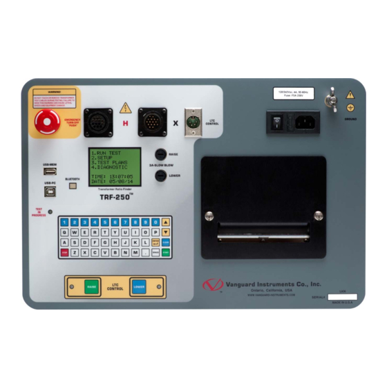
Page 10: Controls And Indicators
REV 1 Controls and Indicators The TRF-250 controls and indicators are shown in Figure 1. A leader line with an index number points to each control and indicator, which is cross-referenced to a functional description in the corresponding table. The purpose of the controls and indicators may seem obvious, but users should familiarize themselves with them before using the TRF-250. -
Page 11: Table 2. Functional Descriptions Of Trf-250 Controls And Indicators
REV 1 TRF-250 USER’S MANUAL Table 2. Functional Descriptions of TRF-250 Controls and Indicators Item Panel Markings Functional Description Number EMERGENCY Emergency turn-off test voltage switch. TURN OFF “PUSH” Back-lit LCD screen (128 x 64 pixels), viewable in bright sunlight and low-light levels. -
Page 12: Pre-Test Setup
TRF-250 USER’S MANUAL REV 1 PRE-TEST SETUP Operating Voltages The TRF-250 can be powered by ac line voltage of 100-240 Vac, 50/60 Hz. LCD Screen Contrast Control [] To increase the LCD screen contrast, press and hold the key for two seconds. Release the button when the desired contrast level has been reached. -
Page 13: Replacing The Load Tap Changer Controller Fuses
Replacing the Load Tap Changer Controller Fuses The TRF-250 features a built-in Load Tap Changer (LTC) controller that can raise or lower the LTC tap position from the front panel. The LTC controller circuit uses two 250 Vac/2A, NO, relay contacts to simulate the LTC Raise/Lower switches. -
Page 14: Operating Procedures
X cables. The transformer bushings should also be grounded before connecting test leads to the transformer. This will prevent inducing any voltages into the TRF-250. All transformer bus connections must be removed, and the transformer must be isolated before performing any tests. -
Page 15: Typical Connections To A Delta-Wye Transformer
REV 1 TRF-250 USER’S MANUAL 3.1.2. Typical Connections to a Delta-Wye Transformer Figure 3. Typical H & X Cable Connections to a Delta-Wye Transformer... -
Page 16: Figure 4. Typical Connections To A Single Phase Transformer
TRF-250 USER’S MANUAL REV 1 3.1.3. Typical Connections to a Single Phase Transformer Figure 4. Typical Connections to a Single Phase Transformer Figure 5. Typical Connections to a Single Phase Auto Transformer... -
Page 17: Figure 6. Typical Connections To A Type A Voltage Regulator
REV 1 TRF-250 USER’S MANUAL 3.1.4. Typical Connections to a Voltage Regulator Figure 6. Typical Connections to a Type A Voltage Regulator Figure 7. Typical Connections to a Type B Voltage Regulator... -
Page 18: Figure 8. Typical Connections To A Donut Type (Un-Mounted) Current Transformer (Ct)
TRF-250 USER’S MANUAL REV 1 3.1.5. Typical Connections to a Donut Type (un-mounted) Current Transformer Figure 8. Typical Connections to a Donut Type (un-mounted) Current Transformer (CT) The H and X test leads are reversed for the CT ratio test connections shown above. -
Page 19: Figure 9. Typical Connections To A Multi-Tap Current Transformer
REV 1 TRF-250 USER’S MANUAL 3.1.6. Typical Connections to a Multi-Tap Current Transformer Figure 9. Typical Connections to a Multi-Tap Current Transformer... -
Page 20: Figure 10. Typical Connections To A Bushing Mount Ct On A Single Phase Transformer
TRF-250 USER’S MANUAL REV 1 3.1.7. Typical Connections to a Bushing Mount CT on a Single Phase Transformer Figure 10. Typical Connections to a Bushing Mount CT on a Single Phase Transformer... -
Page 21: Figure 11. Typical Connections To Bushing Mount Ct's On Delta Transformer
REV 1 TRF-250 USER’S MANUAL 3.1.8. Typical Connections to Bushing Mount CT’s on Delta Transformer Figure 11. Typical Connections to Bushing Mount CT's on Delta Transformer The CT turns-ratio is obtained by performing a Ynd11 test. NOTE... -
Page 22: Figure 12. Typical Connections To Bushing Mount Ct's On Wye Transformer
TRF-250 USER’S MANUAL REV 1 3.1.9. Typical Connections to Bushing Mount CT’s on Wye Transformer Figure 12. Typical Connections to Bushing Mount CT's on Wye Transformer The CT turns-ratio is obtained by performing a Ynyn0 test. NOTE... -
Page 23: Setting The Test Voltage
TRF-250 USER’S MANUAL Setting the Test Voltage The TRF-250 offers four test voltages, 4 Vac, 40 Vac, 100 Vac, and 250Vac. The unit always defaults to 40 Vac at power-on. The 4 Vac test voltage is for testing transformers which require low test voltages, such as metering Current Transformers (CT’s). - Page 24 TRF-250 USER’S MANUAL REV 1 d. The voltage will be set and the following confirmation message will be displayed: 40 volts set Press any key to return to the “START-UP” menu.
-
Page 25: Setting The Date And Time
REV 1 TRF-250 USER’S MANUAL Setting the Date and Time To set the date and time: a. Start from the “START-UP” menu: 1. RUN TEST 2. SETUP 3. TEST PLANS 4. DIAGNOSTIC TIME: 11:23:01 DATE: 08/29/14 Press the key (SETUP). - Page 26 TRF-250 USER’S MANUAL REV 1 e. The following screen will be displayed: ENTER TIME HH:MM:SS Enter the current time using the keypad. When the complete time has been entered, you will be immediately returned to the “START-UP” menu.
-
Page 27: Setting The User Interface Language
REV 1 TRF-250 USER’S MANUAL Setting the User Interface Language To set the user interface language: a. Start from the "START-UP" menu: 1. RUN TEST 2. SETUP 3. TEST PLANS 4. DIAGNOSTIC TIME: 11:23:01 DATE: 09/04/14 Press the key (SETUP). - Page 28 TRF-250 USER’S MANUAL REV 1 e. The preferred user interface language will be set, and the following confirmation screen will be displayed: ENGLISH SET Press any key to return to the "START-UP" menu.
-
Page 29: Clearing The List Of Trusted Bluetooth Devices
Clearing the List of Trusted Bluetooth Devices When the TRF-250 is connected to a PC via Bluetooth for the first time, the PC is added to the unit's list of trusted paired Bluetooth devices. The TRF-250 will then automatically connect to the PC for future uses. - Page 30 TRF-250 USER’S MANUAL REV 1 Press the key (YES). e. The Bluetooth trusted device list will be cleared and the following confirmation screen will be displayed: TRUSTED DEVICE LIST CLEARED! Press any key to return to the "START-UP" menu.
-
Page 31: Performing Tests
REV 1 TRF-250 USER’S MANUAL Performing Tests 3.6.1. Entering Test Record Header Information You can enter the test record header information before performing tests. The record header includes identifying information such as the company, station, circuit, manufacturer, etc. Once the header information has been set, it will apply to all subsequent test records. To enter the header information: a. - Page 32 TRF-250 USER’S MANUAL REV 1 d. The following screen will be displayed: STATION: ↑ ↓ TO POSITION "ENTER" TO ACCEPT [ENTER] Type the station name using the keypad and then press the key. e. The following screen will be displayed: CIRCUIT: ↑...
- Page 33 REV 1 TRF-250 USER’S MANUAL h. The following screen will be displayed: SERIAL NUMBER: ↑ ↓ TO POSITION "ENTER" TO ACCEPT [ENTER] Type the transformer’s serial number using the keypad and then press the key. i. The following screen will be displayed: KVA RATING: ↑...
-
Page 34: Testing A Single Phase Transformer
TRF-250 USER’S MANUAL REV 1 3.6.2. Testing a Single Phase Transformer Follow the steps below to test a single phase transformer: a. Start from the “START-UP” menu: 1. RUN TEST 2. SETUP 3. TEST PLANS 4. DIAGNOSTIC TIME: 11:23:01 DATE:... - Page 35 REV 1 TRF-250 USER’S MANUAL 1. YES Press the key (YES) if you would like to enter the transformer name plate voltage values. The following screen will be displayed. NAME PLATE VOLTAGE: H : X Type the H winding name plate voltage value using the numeric keypad. The...
- Page 36 TRF-250 USER’S MANUAL REV 1 d. The following screen will be displayed: "START" TO TEST "STOP" TO ABORT [START] Press the key to initiate the test. e. The following screen will be displayed while the test is being performed: test in progress please wait...
- Page 37 REV 1 TRF-250 USER’S MANUAL f. The following screen will be displayed: PRINT TEST RESULTS? 1. YES 2. NO Press the key (YES) to print the test results. g. The following screen will be displayed: PRINT FORMAT? 1. COLUMN 2. DETAILED...
- Page 38 TRF-250 USER’S MANUAL REV 1 NOTE restored from Flash EEPROM or from a Flash drive, the following screen will be displayed instead: PREVIOUS DATA IN BUF 1. APPEND PREV. DATA 2. CLEAR PREV. DATA Press the key (APPEND PREV. DATA) to append the data in the unit’s working memory to the current test results, or press the key (CLEAR PREV.
- Page 39 REV 1 TRF-250 USER’S MANUAL k. The following screen will be displayed: SAVE THIS RECORD? 1. YES 2. NO Press the key (YES) to save the test record to the unit’s Flash EEPROM. l. The following screen will be displayed momentarily: SAVING RECORD...
-
Page 40: Table 3. Descriptions Of Single Phase Test Results Elements (Column Format)
TRF-250 USER’S MANUAL REV 1 Figure 13. Single Phase Test Results Printout - Column Format Table 3. Descriptions of Single Phase Test Results Elements (Column Format) Item Description Number Test record date and time. Test record header information (see section 3.6.1). -
Page 41: Figure 14. Single Phase Test Results Printout - Detailed Format
REV 1 TRF-250 USER’S MANUAL Figure 14. Single Phase Test Results Printout - Detailed Format... -
Page 42: Table 4. Descriptions Of Single Phase Test Results Elements (Detailed Format)
TRF-250 USER’S MANUAL REV 1 Table 4. Descriptions of Single Phase Test Results Elements (Detailed Format) Item Description Number Test record date and time. Test record header information (see section 3.6.1). Test voltage. Type of transformer under test. H tap voltage. -
Page 43: Testing A Dyn1 (12,000 V/208 V) Transformer
REV 1 TRF-250 USER’S MANUAL 3.6.3. Testing a Dyn1 (12,000 V/208 V) Transformer Follow the steps below to test a Dyn1 (12,000 V/208 V) transformer: a. Start from the “START-UP” menu: 1. RUN TEST 2. SETUP 3. TEST PLANS 4. DIAGNOSTIC... - Page 44 TRF-250 USER’S MANUAL REV 1 d. The following screen will be displayed: 1. Dyn1 2. Dyn3 3. Dyn5 4. Dyn7 5. Dyn9 6. Dyn11 7. AUTO DETECT Press the key (Dyn1). e. The following screen will be displayed: NAME PLATE VOLTAGE? 1.
- Page 45 REV 1 TRF-250 USER’S MANUAL [ENTER] Press the key. The screen will be updated as shown below: NAME PLATE VOLTAGE: H : X 1,200 : 0 Type the X winding name plate voltage value using the numeric keypad. The screen will be updated as shown below:...
- Page 46 TRF-250 USER’S MANUAL REV 1 The screen will be updated with the Phase A test results as shown: TEST RESULTS: %DIFF RATIO A +100.04 0002 0.11 XFMR TYPE: Dyn1 Testing will continue, and the screen will be updated with the Phase B test results as...
- Page 47 REV 1 TRF-250 USER’S MANUAL i. The following screen will be displayed: PRINT FORMAT? 1. COLUMN 2. DETAILED Press the key (COLUMN) to print a columnar report (see Figure 15) or press the key (DETAILED) to print a detailed report (see Figure 16).
- Page 48 TRF-250 USER’S MANUAL REV 1 m. The following screen will be displayed: SAVE THIS RECORD? 1. YES 2. NO Press the key (YES) to save the test record to the unit’s Flash EEPROM. n. The following screen will be displayed momentarily: SAVING RECORD...
-
Page 49: Figure 15. Dyn1 Test Results Printout - Column Format
REV 1 TRF-250 USER’S MANUAL Figure 15. Dyn1 Test Results Printout - Column Format... -
Page 50: Table 5. Descriptions Of Dyn1 Test Results Elements (Column Format)
TRF-250 USER’S MANUAL REV 1 Table 5. Descriptions of Dyn1 Test Results Elements (Column Format) Item Description Number Test record date and time. Test record header information (see section 3.6.1). Test voltage. Type of transformer under test. Transformer configuration diagrams (H and X). -
Page 51: Figure 16. Dyn1 Test Results Printout - Detailed Format
REV 1 TRF-250 USER’S MANUAL Figure 16. Dyn1 Test Results Printout - Detailed Format... -
Page 52: Table 6. Descriptions Of Dyn1 Test Results Elements (Detailed Format)
TRF-250 USER’S MANUAL REV 1 Table 6. Descriptions of Dyn1 Test Results Elements (Detailed Format) Item Description Number Test record date and time. Test record header information (see section 3.6.1). Test voltage. Type of transformer under test. Transformer configuration diagrams. -
Page 53: Testing A Three Phase Transformer Using Auto Detect Mode
TRF-250 USER’S MANUAL 3.6.4. Testing a Three Phase Transformer Using Auto Detect Mode The TRF-250 provides a convenient Auto Detect mode that can automatically detect 130 specific vector groups for different transformer types defined by ANSI, CEI/IEC, and Australian standards. The transformer configurations supported are listed in Appendix A. The TRF-250 can detect the vector diagrams for Delta-Delta, Wye-Wye, Delta-Wye, and Wye-Delta transformer types. - Page 54 TRF-250 USER’S MANUAL REV 1 d. The following screen will be displayed: 1. YNd1 2. YNd3 3. YNd5 4. YNd7 5. YNd9 6. YNd111 7. AUTO DETECT Press the key (AUTO DETECT). e. The following screen will be displayed: NAME PLATE VOLTAGE? 1.
- Page 55 REV 1 TRF-250 USER’S MANUAL [ENTER] Press the key. The screen will be updated as shown below: NAME PLATE VOLTAGE: H : X 1,734 : 0 Type the X winding name plate voltage value using the numeric keypad. The screen will be updated as shown below:...
- Page 56 TRF-250 USER’S MANUAL REV 1 The TRF-250 will start testing the transformer configurations starting with YNd1. If the transformer is not a type YNd1, it will continue to test for the next type (YNd3, YNd5, etc.) until the transformer type has been determined. The screen will be updated as...
- Page 57 REV 1 TRF-250 USER’S MANUAL Finally, the screen will be updated with the Phase C test results as shown: TEST RESULTS: %DIFF RATIO A +10.057 0.8 0.46 B +10.046 0.7 0.34 C +10.057 0.8 0.46 XFMR TYPE: YNd1 Press any key to continue.
- Page 58 TRF-250 USER’S MANUAL REV 1 l. The following screen will be displayed: TEST SAVED Press any key to continue. m. The following screen will be displayed: RUN ANOTHER TEST? 1. YES 2. NO 3. REPEAT PREV. TEST Press the key (NO).
- Page 59 REV 1 TRF-250 USER’S MANUAL The following confirmation screen will then be displayed: RECORD NUMBER 4 HAS BEEN SAVED! Press any key to return to the “START-UP” menu.
-
Page 60: Working With Test Records
TRF-250 USER’S MANUAL REV 1 Working With Test Records 3.7.1. Saving Test Results to a Test Record After performing a test, the user is presented the option to save the test results to the unit’s Flash EEPROM or to a USB Flash Drive. If the test results are not saved immediately after performing a test, they will still remain in the working memory and can be saved later, as long as a new test has not been performed and the unit has not been turned off. - Page 61 REV 1 TRF-250 USER’S MANUAL d. The following screen will be displayed: 1. SAVE INTERNALLY 2. SAVE TO THUMB DRIVE 1. SAVE INTERNALLY Press the key (SAVE INTERNALLY) to save the test record to the unit’s Flash EEPROM. Continue to step e.
-
Page 62: Restoring A Test Record From Flash Eeprom
TRF-250 USER’S MANUAL REV 1 3.7.2. Restoring a Test Record From Flash EEPROM Use the steps below to restore a test record from the TRF-250’s Flash EEPROM to the working memory: a. Start from the “START-UP” menu: 1. RUN TEST 2. - Page 63 The following screen will be displayed: RESTORE RECORD 1.ENTER RECORD NUMBER 2.SCROLL TO SELECT If you have a USB Flash drive inserted in the TRF-250’s “USB MEM” port, the following screen will be displayed instead of the above screen: NOTE 1.INTERNAL STORAGE 2.THUMB DRIVE...
- Page 64 TRF-250 USER’S MANUAL REV 1 1.2. The following screen will be displayed: RECORD RESTORED! PRINT RECORD? 1.YES 2.NO Press the key (YES) to print the test record. 1.3. The following screen will be displayed: PRINT RECORD 1.PRINT TO LCD 2.PRINT TO PRINTER...
- Page 65 REV 1 TRF-250 USER’S MANUAL 1.4. The basic information about the restored test record will be displayed as shown: YNd1 Num Tests: 1 07/22/10 07:52:50 [] Press the key. The test record details will be displayed as shown: YNd1 8 volts...
- Page 66 TRF-250 USER’S MANUAL REV 1 The basic test record information will be displayed as shown: 07/21/10 09:05 SINGLE PHASE 1 TESTS When you have located the test record that you would like to restored, [ENTER] press the key. Continue to step 1.2 on page 59.
-
Page 67: Restoring A Test Record From A Usb Flash Drive
TRF-250 USER’S MANUAL 3.7.3. Restoring a Test Record From a USB Flash Drive Use the steps below to restore a test record from a USB Flash drive to the TRF-250’s working memory: a. Make sure the USB Flash drive containing the test record(s) is inserted in the TRF-250’s USB Flash drive port (“USB MEM”... - Page 68 TRF-250 USER’S MANUAL REV 1 d. The following screen will be displayed: 1.INTERNAL STORAGE 2.THUMB DRIVE Press the key (THUMB DRIVE). e. The following screen will be displayed: RESTORE THUMB DRIVE REC_ Type the record number that you would like to restore using the keypad. If you do not know the record number, you can first print a test record directory using the instructions in section 3.7.6.
- Page 69 REV 1 TRF-250 USER’S MANUAL g. The following screen will be displayed: PRINT RECORD 1.PRINT TO LCD 2.PRINT TO PRINTER Press the key (PRINT TO LCD) to display the test record date on the unit’s LCD screen. Continue to step h.
- Page 70 TRF-250 USER’S MANUAL REV 1 [] Press the key. The test record details will be displayed as shown below: YNd1 8 volts %DIFF RATIO A +10.057 0.8 0.46 B +10.046 0.7 0.34 C +10.057 0.8 0.46 [STOP] Press the key to return to the “START-UP” menu. The restored test record will...
-
Page 71: Copying Test Records To A Usb Flash Drive
REV 1 TRF-250 USER’S MANUAL 3.7.4. Copying Test Records to a USB Flash Drive Use the steps below to copy one or all test records from the unit’s Flash EEPROM to a connected USB Flash drive: a. Make sure a USB Flash drive is connected to the unit’s “USB MEM” port, and then start from the “START-UP”... - Page 72 1. COPY SINGLE RECORD Press the key (COPY SINGLE RECORD) to copy a single test record from the TRF-250’s Flash EEPROM to the connected USB Flash drive. The following screen will be displayed: ENTER RECORD NUMBER TO COPY TO FLASH DRV...
- Page 73 REV 1 TRF-250 USER’S MANUAL ALL RECORDS HAVE BEEN TRANSFERRED TO THUMB DRIVE! Press any key to return to the “START-UP” menu.
-
Page 74: Printing Or Displaying A Test Record
TRF-250 USER’S MANUAL REV 1 3.7.5. Printing or Displaying a Test Record You can print or display a test record at the time that it is restored (see section 3.7.1 and 3.7.3), or you can restore it to the working memory and print or display it later. To print or display the current test record in the working memory: a. - Page 75 REV 1 TRF-250 USER’S MANUAL PRINT FORMAT? 1.COLUMN 2.DETAILED Press the key (COLUMN) to print the test record in columnar format, or press the key (DETAILED) to print the test record in detailed format. The test record will be printed, and you will be returned to the “START-UP” menu.
-
Page 76: Printing A Test Record Directory
TRF-250 USER’S MANUAL REV 1 3.7.6. Printing a Test Record Directory Follow the steps below to print a directory of the test records stored in the unit’s Flash EEPROM or on a connected USB Flash drive: a. Start from the “START-UP” menu: 1. - Page 77 REV 1 TRF-250 USER’S MANUAL d. The following screen will be displayed: 1. INTERNAL DIRECTORY 2. THUMB DRIVE DIR 1. INTERNAL DIRECTORY Press the key (INTERNAL DIRECTORY) to print a directory of the test records stored in the unit’s Flash EEPROM. Continue to step e.
-
Page 78: Figure 17. Typical Usb Flash Drive (Thumb Drive) Test Record Directory Printout
TRF-250 USER’S MANUAL REV 1 Figure 17. Typical USB Flash Drive (Thumb Drive) Test Record Directory Printout Figure 18. Typical Internal Flash EEPROM Test Record Directory Printout... -
Page 79: Erasing Test Records From The Flash Eeprom
REV 1 TRF-250 USER’S MANUAL 3.7.7. Erasing Test Records from the Flash EEPROM Follow the steps below to erase test records from the Flash EEPROM: a. Start from the “START-UP” menu: 1. RUN TEST 2. SETUP 3. TEST PLANS 4. DIAGNOSTIC... - Page 80 TRF-250 USER’S MANUAL REV 1 If you have a USB Flash drive inserted in the TRF-250’s “USB MEM” port, the following screen will be displayed instead of the above screen: NOTE 1.ERASE INTERNAL REC 2.ERASE THUMB DRV REC Press the key (ERASE INTERNAL REC).
- Page 81 REV 1 TRF-250 USER’S MANUAL The following screen will be displayed while the record is being erased: ERASing record PLEASE WAIT... The following screen will be displayed when the test record has been completely erased: RECORD NUMBER 8 ERASED! Press any key to continue. You will be returned to the beginning of step d.
- Page 82 TRF-250 USER’S MANUAL REV 1 The following screen will be displayed when all test records have been completely erased: RECORDS ERASED! Press any key to return to the “START-UP” menu.
-
Page 83: Erasing Test Records From A Usb Flash Drive
REV 1 TRF-250 USER’S MANUAL 3.7.8. Erasing Test Records from a USB Flash Drive Follow the steps below to erase test records from a USB Flash drive: a. Make sure a USB Flash drive is connected to the unit’s “USB MEM” port, and then start from the “START-UP”... - Page 84 TRF-250 USER’S MANUAL REV 1 d. The following screen will be displayed: 1.ERASE INTERNAL REC 2.ERASE THUMB DRV REC Press the key (ERASE THUMB DRV REC). e. The following screen will be displayed: ERASE RECORD 1.ERASE SINGLE REC. 2.ERASE ALL RECORDS "STOP"...
- Page 85 REV 1 TRF-250 USER’S MANUAL Press any key to continue. You will be returned to the beginning of step e. Press the [STOP] key to return to the “START-UP” menu. 2. ERASE ALL RECORDS Press the key (ERASE ALL RECORDS) to delete all test records from the connected USB Flash drive.
-
Page 86: Working With Test Plans
The TRF-250 comes with the Vanguard Transformer Turns Ratio Analyzer Series 2 software (TTRA S2) that can be used to create transformer test plans on a PC (see the TTRA S2 software manual for details). Test plans can then be transferred to the TRF-250 and used to quickly perform tests. - Page 87 REV 1 TRF-250 USER’S MANUAL c. The following screen will be displayed: 1. INTERNAL STORAGE 2. THUMB DRIVE 1. INTERNAL STORAGE Press the key (INTERNAL STORAGE) to load a test plan from the unit’s Flash EEPROM. Continue to step d.
- Page 88 TRF-250 USER’S MANUAL REV 1 TEST PLAN #001 SAVED! Press any key to continue. The test plan will be loaded in the working memory and also saved to the unit’s Flash EEPROM. You will be returned to the “START-UP” menu. Continue to step e to perform a test using the loaded test plan.
- Page 89 REV 1 TRF-250 USER’S MANUAL f. The following screen will be displayed (test details will differ depending on the test type defined in the test plan): TP #1 YND1 TAPS: TEST PLAN LOADED 1. CONTINUE 2. UNLOAD TEST PLAN The above screen will be displayed only if a test plan is loaded first.
- Page 90 TRF-250 USER’S MANUAL REV 1 i. The following screen will be displayed: PRINT TEST RESULTS? 1.YES 2.NO Press the key (YES) to print the test results. j. The following screen will be displayed: PRINT FORMAT? 1. COLUMN 2. DETAILED Press the...
- Page 91 REV 1 TRF-250 USER’S MANUAL m. If the test plan included multiple tests, the start-up screen for the next test will be displayed as shown: TAP NUMBER 2 H VTG: 4160 X VTG: "START" TO RUN TEST Repeat steps h through l for this test.
-
Page 92: Figure 19. Test Plan Test Results Printout
TRF-250 USER’S MANUAL REV 1 The following confirmation screen will then be displayed: RECORD NUMBER 1 HAS BEEN SAVED! Press any key to return to the “START-UP” menu. Figure 19. Test Plan Test Results Printout... -
Page 93: Unloading A Test Plan From The Working Memory
REV 1 TRF-250 USER’S MANUAL 3.8.2. Unloading a Test Plan From the Working Memory Follow the steps below to unload a test plan from the working memory: a. Start from the “START-UP” menu: 1. RUN TEST 2. SETUP 3. TEST PLANS 4. -
Page 94: Printing A Test Plan Directory
TRF-250 USER’S MANUAL REV 1 3.8.3. Printing a Test Plan Directory Follow the steps below to print a directory of the test plans stored in the unit’s Flash EEPROM or on a connected USB Flash drive: a. Start from the “START-UP” menu: 1. - Page 95 REV 1 TRF-250 USER’S MANUAL c. The following screen will be displayed: 1. INTERNAL DIRECTORY 2. THUMB DRIVE DIR 1. INTERNAL DIRECTORY Press the key (INTERNAL DIRECTORY) to print a directory of the test plans stored in the unit’s Flash EEPROM. The directory will be printed and you will be returned to the “START-UP”...
-
Page 96: Printing A Test Plan
TRF-250 USER’S MANUAL REV 1 3.8.4. Printing a Test Plan Follow the steps below to print a test plan from the internal Flash EEPROM or from a connected USB Flash drive: a. Start from the “START-UP” menu: 1. RUN TEST 2. -
Page 97: Figure 20. Sample Printout Of A Test Plan From A Usb Flash Drive
REV 1 TRF-250 USER’S MANUAL PRINT THUMB DRIVE TP PLAN_ [ENTER] Type the test plan number using the keypad and then press the key. The test plan details will be printed on the unit’s printer and you will be returned to the “START-UP”... -
Page 98: Figure 21. Sample Printout Of A Test Plan From Internal Memory
TRF-250 USER’S MANUAL REV 1 Figure 21. Sample Printout of a Test Plan from Internal Memory... -
Page 99: Saving A Test Plan
REV 1 TRF-250 USER’S MANUAL 3.8.5. Saving a Test Plan Use the steps below to save a test plan from the working memory to the unit’s Flash EEPROM or to a connected USB Flash drive: a. Make sure a test plan is loaded in the working memory, and then start from the “START- UP”... - Page 100 TRF-250 USER’S MANUAL REV 1 PLAN_001 SAVED TO THUMB DRIVE. Press any key to return to the “START-UP” menu. d. The test plan will be saved to the unit’s Flash EEPROM and the following screen will be displayed: TEST PLAN #001 SAVED!
-
Page 101: Copying A Test Plan To A Usb Flash Drive
REV 1 TRF-250 USER’S MANUAL 3.8.6. Copying a Test Plan to a USB Flash Drive Use the steps below to copy a test plan from the unit’s Flash EEPROM to a connected USB Flash drive: a. Make sure a USB Flash drive is connected to the unit’s “USB MEM” port, and then start from the “START-UP”... - Page 102 TRF-250 USER’S MANUAL REV 1 Any existing test plans in the Flash drive will NOT be over-written. NOTE Press any key to return to the “START-UP” menu.
-
Page 103: Erasing Test Plans
REV 1 TRF-250 USER’S MANUAL 3.8.7. Erasing Test Plans Follow the steps below to erase a test plan from the unit’s Flash EEPROM or from a connected USB Flash drive: a. Start from the “START-UP” menu: 1. RUN TEST 2. SETUP 3. - Page 104 TRF-250 USER’S MANUAL REV 1 ERASE TEST PLAN 1. ERASE SINGLE PLAN 2. ERASE ALL PLANS 1. ERASE SINGLE PLAN Press the key (ERASE SINGLE PLAN) to erase a single test plan from the connected USB Flash drive. The following screen will be displayed:...
- Page 105 REV 1 TRF-250 USER’S MANUAL To proceed with erasing all the test plans from the connected USB Flash [ENTER] drive, press the key. All test plans will be erased from the USB Flash drive and the following message will be displayed:...
- Page 106 TRF-250 USER’S MANUAL REV 1 2. ERASE ALL PLANS Press the key (ERASE ALL PLANS) to erase all test plans from the unit’s internal Flash EEPROM. The following warning screen will be displayed: ERASE ALL PLANS! ARE YOU SURE? "ENTER" TO CONTINUE.
-
Page 107: Diagnostics, Verification, And Troubleshooting
REV 1 TRF-250 USER’S MANUAL DIAGNOSTICS, VERIFICATION, AND TROUBLESHOOTING Performing an H and X Cable Diagnostic Test Use the steps below to perform a diagnostic test on the H and X cables: a. Start from the “START-UP” menu: 1. RUN TEST 2. - Page 108 TRF-250 USER’S MANUAL REV 1 The screen will be updated with the status of each test as shown: cable test H0-X0, H1-X1: OK H0-X0, H2-X2: OK H0-X0, H3-X3: OK “NOT OK” will be displayed for a failed diagnostic test. NOTE...
-
Page 109: Performing A Verification Test
[ENTER] Connect the H and X cables per the on-screen instructions and then press the key. d. The TRF-250 will start performing a DELTA-DELTA test. The following screen will be displayed momentarily: DELTA-DELTA TEST The screen will then be updated with the test results for each phase:... - Page 110 TRF-250 USER’S MANUAL REV 1 TEST RESULTS RATIO %DIFF A +1.0000 0001 B +1.0000 0001 C +1.0000 0001 XFMR TYPE: Dd0 The unit will then proceed to perform a Y to Y test. The following screen will be displayed momentarily:...
-
Page 111: Appendix A - Transformer Vector Group Codes
REV 1 TRF-250 USER’S MANUAL APPENDIX A – TRANSFORMER VECTOR GROUP CODES Utility power transformers manufactured in accordance with IEC specifications have a Rating Plate attached in a visible location. This plate contains a list of the transformer's configuration and operating specifications. One such rating is the winding configuration and phase- displacement code. -
Page 112: Appendix B - Common Ansi Transformer Descriptions
TRF-250 USER’S MANUAL REV 1 APPENDIX B – Common ANSI Transformer Descriptions... - Page 113 REV 1 TRF-250 USER’S MANUAL...
- Page 114 TRF-250 USER’S MANUAL REV 1...
- Page 115 REV 1 TRF-250 USER’S MANUAL...
- Page 116 TRF-250 USER’S MANUAL REV 1...
- Page 117 REV 1 TRF-250 USER’S MANUAL...
- Page 118 TRF-250 USER’S MANUAL REV 1...
- Page 119 REV 1 TRF-250 USER’S MANUAL...
-
Page 120: Appendix C - Cei/Iec 60076-1 Transformer Descriptions
TRF-250 USER’S MANUAL REV 1 APPENDIX C – CEI/IEC 60076-1 Transformer Descriptions... - Page 121 REV 1 TRF-250 USER’S MANUAL...
- Page 122 TRF-250 USER’S MANUAL REV 1...
- Page 123 REV 1 TRF-250 USER’S MANUAL...
- Page 124 TRF-250 USER’S MANUAL REV 1...
- Page 125 REV 1 TRF-250 USER’S MANUAL...
- Page 126 TRF-250 USER’S MANUAL REV 1...
-
Page 127: Appendix D - Australian Std.2374 Transformer Descriptions
REV 1 TRF-250 USER’S MANUAL APPENDIX D – Australian Std.2374 Transformer Descriptions... - Page 128 TRF-250 USER’S MANUAL REV 1...
- Page 129 REV 1 TRF-250 USER’S MANUAL...
- Page 130 TRF-250 USER’S MANUAL REV 1...
- Page 131 REV 1 TRF-250 USER’S MANUAL...
- Page 132 TRF-250 USER’S MANUAL REV 1...
- Page 133 REV 1 TRF-250 USER’S MANUAL...
- Page 134 1520 S. Hellman Ave • Ontario, CA 91761 • USA Phone: 909-923-9390 • Fax: 909-923-9391 www.vanguard-instruments.com Copyright © 2018 by Doble Engineering Company TRF-250 User’s Manual • Revision 1.1 • July 9, 2018 • TA...
Need help?
Do you have a question about the TRF-250 and is the answer not in the manual?
Questions and answers