Table of Contents

Related Manuals for Kanomax DALT 6900


Summary of Contents for Kanomax DALT 6900
- Page 1 OPERATION MANUAL Version 3 Duct Air Leakage Tester Model DALT 6900 Be sure to read this manual thoroughly before using the instrument. Please keep this manual as a service reference. Kanomax Duct Air Leakage Tester Operation Manual Ver.3...
- Page 2 Component List Standard: ITEM Model Duct Air Leakage Tester (main unit) 6900 Flow Grid Low flow nozzle Ø6 Silicone tube (white) Duct connection hose Power cord Container Ø 6 Silicon tube (blue) Ø 6 Silicon tube (red) Calibration certificate Optional Extras: ITEM Model Static pressure probe...
- Page 3 AC adapter and remove the batteries immediately. Then send it to the the AC adapter and remove the batteries immediately. Then send it to the maintenance Dept. of KANOMAX for after service. maintenance Dept. of KANOMAX for after service.
- Page 4 CAUTION Always unplug when the instrument not in use. Always unplug when the instrument not in use. ○ Failure to do so may cause an electric shock, Failure to do so may cause an electric shock, a fire or circuit damage. fire or circuit damage.
-
Page 5: Table Of Contents
CONTENTS Introduction ................................. 6 1.1. Product features ............................6 1.2. Main Specifications ............................7 Outlook & Structure ............................. 8 2.1. Construction ..............................8 2.2. Controller structure ............................8 3.Installation and Assembling ............................9 3.1.Testing duct connection ..........................9 3.2.High- flow testing ............................10 3.3.Low- flow testing ............................ -
Page 6: Introduction
1. Introduction Duct Air Leakage Tester is mainly used for HVAC duct air leakage testing. Testing can be in sections and the overall pipeline after whole system installation to make the HVAC system effective and avoiding energy waste. Model 6900 can judge the whether the duct seal is qualified based on and compliant with the corresponding accreditation standard. -
Page 7: Main Specifications
2% of Reading Resolution 0.1 in.Hg (0.1 kPa) Power Source 100-120V, 1 Phase, 50/60Hz,16A DALT 6900-0E (DALT 6900 does not operate with temporary DALT 6900-1E 200-240V, 1 Phase, 50/60Hz,10A power from an insufficient power supply.) 420(Foot print)Sq.in.x 47 (Height) inches Main unit Dimensions 21 (Wide) x 20 (Depth)x 47 (Height) inches... -
Page 8: Outlook & Structure
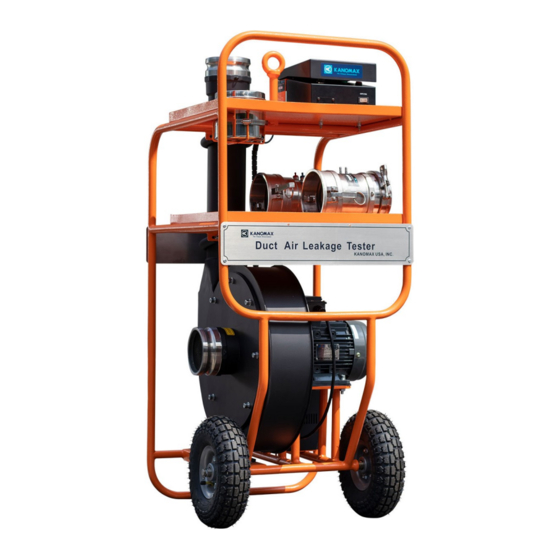
2. Outlook & Structure Outlook & Structure 2.1. Construction Fan Outlet Controller Container Low flow nozzle Fan Inlet Power source 2.2. Controller structure Display screen Fan Speed Fan Stop Switch Control Fan Run Switch Power On/Off Duct Air Leakage Tester Operation Manual Ver. Duct Air Leakage Tester Operation Manual Ver.3... -
Page 9: Installation And Assembling
Connect the testing duct to the Tester : (1) Position the DALT 6900 unit as close to the remaining opening in the ductwork as possible to minimize the flexible tubing needed. Minimize bends in the flexible tubing to reduce the pressure loss, giving the best performance. -
Page 10: High- Flow Testing
3.2.High- flow testing High- flow testing takes Matrix grid as the tool for Duct leakage flow measuring. Connect the matrix grid tool to the fan outlet, tight locking the cam Lock to ensure proper fit. Connect the flow grid pressure tap to the Differential pressure flow port of the controller cabinet. -
Page 11: Low- Flow Testing
3.3.Low- flow testing Low- flow testing takes nozzles as the tool for Duct leakage flow measuring. Install the low-flow nozzles to the blower outlet, tight locking the cam lock adaptor. Connect the pressure tap of the nozzle to the Differential pressure flow port of the controller cabinet. -
Page 12: Operatinginstructions
4.1.Power On 1. Power source: AC power supply with a Transient protector : AC power supply with a Transient protector is for DALT 6900. Before turning on for start . Before turning on for start measuring, check and ensure the correct and securely connection behind the controller cabinet. - Page 13 the testing. Click “Accreditation” to access the Application menu. to access the Application menu. inputting Duct Surface Surface Area. Select the Flow Device. Click ……. to Test time setting . to Test time setting NEXT NEXT Click Click for Testing standard selection for Testing standard selection Click ….
- Page 14 Through after the setting time, output display Through after the setting time, output display Real-time displaying the static pressure in duct. time displaying the static pressure in duct. the testing result. When pressure statically, click hen pressure statically, click NEXT NEXT Click SAVE...
-
Page 15: Measure" Menu
4.3“Measure” menu Measure items include: airflow, static pressure, temperature and atmosphere. Measure items include: airflow, static pressure, temperature and atmosphere. When pressure is adjusted to the request, When pressure is adjusted to the request, click for start Airflow testing. for start Airflow testing. Click “Measure”... -
Page 16: Setting" Menu
4.4“Setting” menu In “Setting” menu, application items include: D nu, application items include: Date, Time, STD/ACT, Temperature, Atmosphere, Air flow and , Temperature, Atmosphere, Air flow and Static pressure as shown below. 1. Date setting Press Press for modifying data. for modifying data. -
Page 17: My Data" Menu
4.5“My Data” menu 1. Press for page turning browsing. for page turning browsing. 2.Click the serial No. on upper right corner for data reviewing Click the serial No. on upper right corner for data reviewing 3. Through Delete range settings for deleting selected data. range settings for deleting selected data. -
Page 18: Usb"Menu
4.6“USB”menu The data record can be output by U The data record can be output by USB disk. When insert USB disk to USB connector, it will be found by the system and all the saved data will be disk to USB connector, it will be found by the system and all the saved data will be disk to USB connector, it will be found by the system and all the saved data will be output. -
Page 19: Error And Troubleshooting
5.Error and Troubleshooting Symptom Possible causes Corrective action Power connect failure Check the power source and connecting wire Controller start failure Internal circuit problem Connect with manufacturer Power phase shortage Check the power supply Motor controller line is not Check the Motor Control line on the back of Fan motor will not run connected or poor connect. -
Page 20: Warranty And Service
This limited warranty covers all defects encountered in normal use of the PRODUCT, and does not apply in the following cases: (1) Use of parts or supplies other than the PRODUCT sold by KANOMAX GROUP COMPANIES, which cause damage to the PRODUCT or cause abnormally frequent service calls or service problems. - Page 21 During the warranty period, we will repair at no charge a product that proves to be defective due to material or workmanship under normal use. All return shipping charges are the responsibility of the customer. Repair after warranty expiration: Upon request, we will repair the instrument at the customer’s expense, if the instrument’s performance is found to be recoverable by providing the repair.
-
Page 22: Appendix1 Leakage Testing Standards
Appendix1 Leakage Testing Standards County Standard Description Ventilation for buildings—Ductwork—Strength and leakage of circular BS EN 12237:2003 sheet metal ducts. Ventilation for buildings—Sheet metal air ducts with rectangular BS EN 1507:2006 section—Requirements for strength and leakage. DW/143 HVAC—A practical guide to Ductwork leakage testing. Eurovent 2/2 Air leakage rate in sheet metal air distribution systems. - Page 23 0.003 × P 1000 2000 1000 0.001 × P 1000 2000 1000 * Class D ductwork is only for special apparatus 3. EU Standards Dw/143 Static Pressure Limit Maximum Air Velocity Air leakage limits Duct Pressure Class l/s/m Positive Pa Negative Pa Low-pressure –...
- Page 24 6. US Standards AABC Maximum Type of System Minimum Test Pressure Allowable Leakage Fractional horsepower system; coils, small 0.50’’WC(125Pa) exhaust/supply fans, and residential system Small systems; split DX systems – usually systems under 2000 1.00’’WC(250Pa) CFM(940l/s),and residential systems VAV and CAV terminal boxes and associated downstream 1.00’’WC(250Pa) ductwork Single zone, multi-zone, return ducts, and exhaust duct systems...
- Page 25 7. GB Standard GB50243 Rectangle Duct pressure class Maximum Leakage m /h/m Low-pressure system 0.1056 × P Medium pressure system 0.0352 × P High pressure system 0.0117 × P P-- Working pressure(Pa) of the Duct system. 1.The allowable air leakage for the Round Metal Duct of low pressure and medium pressure, composite material duct and Illegal orchid form of nonmetallic duct should be 50% of the regulated leakage value of the rectangle duct.
-
Page 26: Appendix2 Fan Performance Graph
Appendix2 Fan Performance Graph Volume Flow CFM Duct Air Leakage Tester Operation Manual Ver.3... -
Page 27: Appendix3 Installation Instruction
Appendix3 Installation Instruction Installation Instruction Take special care Take special care with joints sealing with joints sealing Blank off all open ends Blank off all open ends Minimize bends in Minimize bends in the flexible tubing to the flexible tubing to Static Pressure Tube tatic Pressure Tube reduce the pressure... - Page 28 Copyright © Kanomax USA, Inc. All rights reserved. 2016 No copying, distribution, publication, modification, or incorporation of this document, in whole or part, is permitted for commercial purposes without the express written permission of Kanomax. The contents of this document may be changed without prior notice.
Need help?
Do you have a question about the DALT 6900 and is the answer not in the manual?
Questions and answers