Table of Contents
Advertisement
Quick Links
Advertisement
Table of Contents

Related Manuals for Renishaw TB20


Summary of Contents for Renishaw TB20
- Page 1 TB20 user guide F-8003-4496-02-A TB20 quadrature trigger box...
-
Page 2: Legal Information
Renishaw plc or its subsidiaries. Renishaw reserves the right to make changes to this document and to the product All other brand names and product names used in this document are trade described herein without obligation to notify any person of such changes. -
Page 3: International Regulations And Conformance
Quadrature trigger box Legal information International regulations and conformance RoHS compliance Compliant with EC directive 2011/65/EU (RoHS). EC compliance Renishaw plc declares that the TB20 quadrature trigger box complies with the Packing material information applicable standard and regulations. Packaging Recycling Material... -
Page 4: Table Of Contents
Power LED ............22 Safety labelling ............6 Status LED ............23 Mechanical safety ...........7 System specifications ..........24 Electrical and power safety ........7 Encoder types supported ........25 What is TB20? ............8 Environment ............26 TB20 kit components ..........9 Maximum velocities ..........26 TB20 interface ............10... -
Page 5: Safety Information
If the lines are not in opposing states, the motion must be stopped. The TB20 can be used in a variety of environments and applications. To ensure the safety of the user and other personnel in the vicinity it is therefore paramount 3. -
Page 6: Safety Labelling
HARMFUL INTERFERANCE. (2)THIS DEVICE MUST ACCEPT ANY INTERFERENCE RECEIVED. INCLUDING INTERFERENCE THAT MAY CAUSE UNDESIRED OPERATIONS. There are no user-serviceable parts inside the TB20. Do not remove any part of the housing. Ensure that you read and understand the TB20 user guide before using any TB20. -
Page 7: Mechanical Safety
• Beware of trip hazards that may be created when using the TB20 in • The TB20 has been qualified for use with the power supply cable and the conjunction with other systems. e.g. due to trailing cables. plug adaptor kit supplied with the system. A specification for the power supply requirements can be found here. -
Page 8: What Is Tb20
TB20 is an interface which is used with Renishaw’s XL laser calibration system. • TB20 receives quadrature input pulses from an encoder system. TB20 reads output from an encoder and generates a trigger for the laser system at predetermined intervals. Typical uses are leadscrew calibration and motion •... -
Page 9: Tb20 Kit Components
Quadrature trigger box TB20 kit components TB20 trigger box XL trigger cable Power supply cable Plug adaptor kit TB20 encoder and controller port connectors Calibration user guide card M-9904-4443-01-A Laser calibration user guides Laser calibration user guides can be found at: Benutzerhandbücher zur Laserkalibrierung finden Sie unter:... -
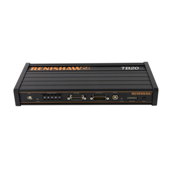
Page 10: Tb20 Interface
Quadrature trigger box TB20 interface USB port Power LED Trigger interval switches Encoder port Controller port Trigger port Status LED Configuration switches Reset switch... -
Page 11: Tb20 Configurations
Quadrature trigger box TB20 configurations Open loop Closed loop... -
Page 12: Test Overview
Quadrature trigger box Test overview XL-80 set-up (For XL-80 set-up procedure please refer to XL-80 user guide) Set-up TB20 set-up Trigger interval set-up Configuration Switch set-up Data capture Capture Data analysis... -
Page 13: Tb20 Set-Up
Connect the controller to the controller port (if required) Connect the trigger port on TB20 to auxillary I/O connector on the XL laser Configure switch settings Connect the USB power supply to the electrical outlet Note: for TB20 encoder and controller port pin-outs refer to Appendix A. -
Page 14: Trigger Interval Set-Up
Trigger interval set-up To configure the trigger interval on the TB20 the ‘trigger interval’ switch is used. The input is a decimal value (“00000” is not permitted). The values for this switch can be set by reference to the table below or by calculation on the following page. - Page 15 Quadrature trigger box Trigger interval set-up TB20 setting (in decimal) = desired trigger interval (microns) For custom trigger interval use the calculation: 2 × encoder resolution (microns) Where the encoder resolution is defined as: RS422 digital quadrature Analogue quadrature Pitch...
-
Page 16: Switch Set-Up
Quadrature trigger box Switch set-up The TB20 must be configured to specify the type of encoder connected and the type of trigger required. This is achieved using the ‘configuration switches’. Switch number 6,7,8 Function Trigger direction Encoder type Encoder type... -
Page 17: Data Capture
Quadrature trigger box Data capture Two types of data capture can be achieved with TB20 using the XL-80 TPin function: • Quasi-static – the bed moves via predefined intervals and stops for the measurement to be taken • Dynamic – the bed moves continuously and TB20 triggers measurements to be taken It is recommended to perform the quasi-static data capture using CARTO Capture, whereas dynamic data capture will require LaserXL software. -
Page 18: Data Capture Reset Button
The ‘RESET’ button provides the following functionality: • Datum and capture the first point at the beginning of a test. • Clear any error conditions logged by the TB20 (providing the source of the error has been removed). • Update any changes to switch configurations. -
Page 19: Quasi-Static Data Capture Using Carto Capture
Quadrature trigger box Quasi-static data capture using CARTO Capture - For full details on Capture please refer to the Capture user guide... -
Page 20: Dynamic Data Capture Using Laserxl Dynamic Measurement
Quadrature trigger box Dynamic data capture using LaserXL dynamic measurement - For full details on Dynamic data capture and analysis please refer to the LaserXL user guide. -
Page 21: Data Analysis
Quadrature trigger box Data analysis On completion of the test select Analyse to launch Explore. Note: For full details on Explore please refer to the Explore user guide. Dynamic data capture currently not supported in CARTO. Please refer to XCal-View data analysis software. -
Page 22: Diagnostics
Green TB20 and encoder powered by an external USB power supply If controller port is attached to the controller, the TB20 is powered from the USB power supply and encoder from the controller Blue TB20 and encoder powered by the controller... -
Page 23: Status Led
Quadrature trigger box Diagnostics Status LED This LED provides the current status of the TB20. LED status Description Green Referenced - normal operating mode. Trigger green Trigger pulse is generated, green LED alternates between green and grey Amber Not referenced – no triggers are generated. This occurs when: •... -
Page 24: System Specifications
Refer to Appendix for unsensed and sensed power supply configuration wiring details accordingly. Input voltage 5 Vdc ±5% Maximum input current TB20 current 250 mA (with no encoder connected) requirement Encoder power 5 Vdc ±5%, capable of providing 500 mA current to encoder supply... -
Page 25: Encoder Types Supported
Quadrature trigger box Encoder types supported TB20 is compatible with analogue and digital quadrature encoders that require a 5V power supply. It supports: • Analogue 1 Vpp encoder • Analogue microcurrent encoder • Digital encoder Note: refer to the encoder manufacturers installation manual for cabling and shielding recommendations. -
Page 26: Environment
Quadrature trigger box Environment Operating and storage humidity 0% to 95% RH Non-condensing Operating temperature 0 ˚C to 50 ˚C Storage temperature -20 ˚C to 70 ˚C Maximum velocities The maximum velocity for analogue encoder applications is 1 m/s. Digital encoder velocities are as follows: Resolution Velocity m / s 0.05 µm... -
Page 27: Weights And Dimensions
Quadrature trigger box Weights and dimensions Weight TB20: complete kit 1 kg 294 mm... -
Page 28: Wiring
** Connect 5 V to 5 V link and 0 V to 0 V link at the encoder if a sensed supply is used. The power supply should always be connected to the 5 V and 0 V ports. The TB20 can handle up to 0.5 V drop on both supply and return lines i.e. 5 V ±0.5 V maximum. The controller supply should be limited to a maximum output of 6.5 V. -
Page 29: Accuracy
Accuracy The following factors affect the overall accuracy of the measurement: • Use of TB20 introduces no additional factors affecting accuracy of laser measurement. For full details please refer to the XL-80 manual. Delays in open loop TB20 introduces a delay in the encoder quadrature signals being received by the controller as per the table below: Quadrature input –... -
Page 30: Accuracy - Delays In Closed Loop
Quadrature trigger box Appendix B Accuracy - Delays in closed loop Quadrature output – trigger delay The quadrature signals are regenerated inside the TB20 to be terminated to the machine controller. Encoder type Delay (µs) Effect on accuracy at different speeds (µm) 0.25 m/s... - Page 31 Renishaw plc +44 (0)1453 524524 +44 (0)1453 524901 New Mills, Wotton-under-Edge uk@renishaw.com Gloucestershire, GL12 8JR United Kingdom www.renishaw.com For worldwide contact details, visit www.renishaw.com/contact *F-8003-4496-02* Issued: 01.2021 Part no. F-8003-4496-02-A © 2017-2021 Renishaw plc...
Need help?
Do you have a question about the TB20 and is the answer not in the manual?
Questions and answers