
Related Manuals for Renishaw PI 200-3


Summary of Contents for Renishaw PI 200-3
- Page 1 PI 200-3 installation guide www.renishaw.com PI 200-3 installation guide Document part number: H-1000-7542-03-B Stand alone unit Card option to fit inside PHC10-3 PLUS Issued 01 2018...
-
Page 2: General Information
Renishaw distributor. Warranty Renishaw plc warrants its equipment for a limited period (as set out in our Standard Terms and Conditions of Sale) provided that it is installed exactly as defined in associated Renishaw documentation. Prior consent must be obtained from Renishaw if non-Renishaw equipment (e.g. interfaces and/or cabling) is to be used or substituted. - Page 3 Renishaw probes and associated systems are precision tools used for obtaining precise measurements and must therefore be treated with care. Changes to Renishaw products Renishaw reserves the right to improve, change or modify its hardware or software without incurring any obligations to make changes to Renishaw equipment previously sold. Packaging...
-
Page 4: Eu Declaration Of Conformity
PI 200-3 installation guide www.renishaw.com EU declaration of conformity Contact Renishaw plc or visit www.renishaw.com/productcompliance for the full EU declaration. Issued 01 2018... - Page 5 Information to user (47CFR section 15.21) The user is cautioned that any changes or modifications not expressly approved by Renishaw plc or authorised representative could void the user's authority to operate the equipment.
- Page 6 Installation category II The PI 200-3 is isolated from ac power by disconnection of the IEC mains connector from the supplied PSU. If any additional means of isolation is required , it must be specified and fitted by the machine manufacturer or installer of the product. The isolator / disconnection device must be sited within easy reach of the operator and comply with any applicable national wiring regulations for the country of installation.
-
Page 7: Environmental Conditions
PI 200-3 installation guide www.renishaw.com Environmental conditions The following environmental conditions comply with those defined in BS EN61010 - 1:2001: Indoor use IP30 (no protection against water) Altitude Up to 2000 m Operating temperature 0 °C to +50 °C Storage temperature 10 °C to +70 °C Relative humidity 80% maximum for temperatures up to +31 °C... - Page 8 Introduction The TP200 probe system comprises the TP200 probe sensor and stylus module, the PI 200-3 interface and the optional SCR200 stylus change rack. The TP200 is a 13.5 mm diameter touch-trigger probe with the facility to quickly change stylus configurations without the need for requalification.
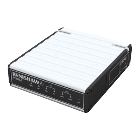
- Page 9 PI 200-3 installation guide www.renishaw.com The image below shows the PI 200-3 stand alone version (A-5707-0100): The image below shows the PI 200-3 integrated card version (A-5707-0200) that is intended to be used in conjunction with PHC10-3 PLUS: (for representation only)
-
Page 10: Product Description
At power-up, or when a probe is first connected, the PI 200-3 recognises whether the probe is a kinematic switching probe (TP20 / TP6 / TP2 type) or a TP200, and automatically selects the appropriate operating mode. - Page 11 PI 200-3 installation guide www.renishaw.com SYNC and HALT signal timing for a TP200 gauge point SYNC and HALT signal timing for a gauge point when a kinematic probe is connected Issued 01 2018...
-
Page 12: Probe Damped Signal (Pdamp)
During high-speed position moves (fast traverse), it is necessary to reduce probe sensitivity to prevent vibration causing unwanted triggers. The CMM controller must assert the PDAMP signal on the PICS port, to switch the PI 200-3 into the low sensitivity mode known as ‘probe damped'. In this mode, deflection of the stylus will generate SYNC and HALT simultaneously, but only if the probe signal remains... -
Page 13: Stylus Mass And Ambient Temperature Compensation
Fine compensation for thermal drift is provided by a system known as ‘autozero' that nulls the sensor amplifiers at a slow rate when the probe is armed. Under the control of the PI 200-3 interface, the autozero automatically switches to a fast rate to reset the probe sensors during a stylus change with the SCR200 change rack or during reorientation of a motorised probe head. -
Page 14: Front Panel Indicators
PI 200-3 installation guide www.renishaw.com Front panel indicators PI 200-3 front panel indicators Indicator Colour Function POWER ON Green Power on STOP PICS - STOP asserted TYPE TP200 Green TP200 probe selected TYPE STD Green Kinematic probe selected PROBE SEATED... -
Page 15: Audible Indicator
PI 200-3 installation guide www.renishaw.com PHC10-3 PLUS front panel indicators Indicator Colour Function POWER ON Green Power on STOP PICS - STOP asserted HEAD READY Green Head ready HEAD ACTIVE Amber Head active ERROR DATUM Error datum ERROR OBSTRUCT Error obstruct... -
Page 16: Rear Panel Switches And Connectors
HALT active LOW Head LED control External control via PICS DOWN LED mimics SYNC STOP disabled PI 200-3 ignores PICS - STOP DOWN STOP asserts HALT/SYNC SYNC polarity SYNC HIGH and SSR closes on trigger DOWN SYNC LOW and SSR opens on trigger... - Page 17 PI 200-3 installation guide www.renishaw.com Switch 2: Selects control of the LEDOFF output to either internal PI 200-3 control according to the status of SYNC, or sets the output to high impedance for control of the head LED by external switching. Switch 3: Sets the PI 200-3's response to STOP when asserted from an external source.
- Page 18 PI 200-3 installation guide www.renishaw.com SYNC debounce options Switch 10: In operating situations where there is an unusually high level of background vibration, it may be necessary to reduce the sensitivity of the TP200 to avoid false ‘air' triggers. These may occur on some types of CMM when large steel stylus arrangements are used or where the CMM is inadequately isolated from the floor transmission of vibration from nearby machinery or vehicle traffic.
- Page 19 Sliding the switch to the REV position should allow normal operation. Incorrect setting of the polarity switch should not damage the probe. When the PI 200-3 is added to the PHC10-3 PLUS, the STOP light will flash at approximatly 3 Hz. All PI 200-3 interface LEDs should be OFF.
-
Page 20: Connector Pinouts
PI 200-3 installation guide www.renishaw.com Connector pin-outs PICS input connector The PICS input connector is a 9 pin ‘D' type socket. The pin numbers are illustrated and their functions are shown in table. Pin number Description Pin number Description STOP STOP +5 V pull-up PPOFF PDAMP Ground (0 V) LEDOFF LED anode Probe signal ground Probe signal input Shell Screen PICS output connector The PICS output connector is a 9 pin ‘D' type plug. The pin numbers are illustrated and their functions are shown in the table. -
Page 21: Ssr Output Connector
Screen Stylus change rack (SCR) output connector The SCR200 stylus change rack is connected to the PI 200-3 via a 6 pin miniature DIN socket. The pin numbers are illustrated and their functions are shown in the table. SCR200 output connector (view on rear panel) -
Page 22: Remote Reset
There are two methods of connection to a remote push button that will achieve the same effect as the RESET button on the front panel of the PI 200-3 interface. This may be useful if manual stylus changing is frequent, or if the PI 200-3 is difficult for the operator to access. -
Page 23: Pi 200-3 Dimensions And Cable Data
PI 200-3 installation guide www.renishaw.com PI 200-3 dimensions and cable data Dimensions 1/3 rack wide × 1U high 155 mm × 44 mm × 180 mm deep Weight 1.25 kg Mounting method 19 in rack or freestanding Mounting screws M5 × 6 mm maximum penetration Probe voltage (open circuit) 12.4 V Maximum 5 Ω / conductor Probe cable resistance Probe cable length... -
Page 24: Part Number Summary
Part number summary Interfaces: Description Part number PI 200-3 interface A-5707-0100 PI 200-3 intergrated interface (used with PHC10-3) A-5707-0200 Probe kits: Description Part number TP200 probe kit 1 (including standard force module) A-1207-0001* TP200 probe kit 2 (including low force module) - Page 25 Rotary adjustment module: autojoint to M8 A-1051-0679 Replacements: Description Part number User's guide: TP200 probe system (English) H-1000-5014 Installation guide: PI 200-3 interface for TP200 probe system (English) H-1000-5029 CK200 cleaning material A-1085-0016 S1 'C' spanner A-1042-1486 S9 double-ended 'C' spanner...
-
Page 26: Installation Procedure
Insert the PI 200-3 card, ensuring that the card is located in the correct grooves shown in the illustration below. Insert the reset actuator over the top of the reset button on the PI 200-3 card and then replace the end panel. - Page 27 PI 200-3 installation guide www.renishaw.com Issued 01 2018...
-
Page 28: Upgrading To Tp200 (Retrofit)
If upgrading from TP2, star or offset (cranked) stylus arrangements will require a minimum 5 mm extension piece to be added for use with the TP200 If cables other than those supplied by Renishaw are used, equivalent cable screening and connector bonding must be used to maintain compliance with the EMC standards System interconnection Interconnection diagrams for the most common product combinations. - Page 29 PI 200-3 installation guide www.renishaw.com PI 200-3 interconnection with MH8 PI 200-3 interconnection with MIH head Issued 01 2018...
- Page 30 PI 200-3 installation guide www.renishaw.com PHC10-2 and PI 200-3 interconnection with PH10M Issued 01 2018...
- Page 31 PI 200-3 installation guide www.renishaw.com PI 200-3 card with PHC10-3 PLUS interconnection with PH10T PLUS and SCR200 PI 200-3 with PHC10-3 PLUS interconnection with PH10M PLUS and SCR200 Issued 01 2018...
- Page 32 PI 200-3 installation guide www.renishaw.com PI 200-3 card and PHC10-3 PLUS interconnection with PH10 PLUS and AC3 PI 200-3 and PHC10-3 PLUS interconnection with PH10 PLUS and AC3 Issued 01 2018...
-
Page 33: Using Tp200 With The Acr1 Autochange System
PI 200-3 and two SCR200 racks The miniature DIN connector on the base of the SCR200 rack is connected to the SCR200 connector on the PI 200-3 rear panel using cable PL63 / PL64 / PL65 according to the length required. For applications requiring two racks, a dual rack splitter cable is needed. -
Page 34: Interconnection Cables
PI 200-3 installation guide www.renishaw.com Interconnection cables Cable number Cable ident Length Part number Notes 260 mm to 710 mm (10.24 in to 27.95 in) A-1016-0004 Coiled 410 mm to 1.27 m (16.14 in to 50 in) A-1016-0006 Coiled 680 mm to 2.32 m (26.77 in to 91.34 in) -
Page 35: Rack Mounting
To mount the PI 200-3 in a 19 inch cabinet, two 1/3 blanking panel kits are required (Renishaw part number A-1018-0179). Fit the panels using the M5 × 6 mm long screws provided. Mounting PI 200-3 with PHC10-2 To mount a PI 200-3 next to a PHC10-2 controller in a 19 inch cabinet, a bracket kit is required (Renishaw part number A-1018-0173). Fit the panels using the M5 × 6 mm long screws provided. Issued 01 2018... -
Page 36: Pics Terminations
The Renishaw product interconnection system (PICS) has been developed to standardise the format for real-time communications between Renishaw products and the CMM controller. PICS facilitates the integration of multiple probe interfaces and system controllers without the need for additional hardware or software overheads on the CMM controller. -
Page 37: Maintenance
PI 200-3 installation guide www.renishaw.com Maintenance Periodically check the security of the mounting screws and electrical connectors. Remove dust from the external surfaces with a dry, lint free cloth. Issued 01 2018... -
Page 38: Power Supply
This is a 24 Vdc 49 W supply and is connected to the PI 2003 via Ø5.5 mm dc jack plug. PI 200-3 does not require a protective earth, however an equipotential bonding point is provided on the rear panel for connection to the rest of the installation. PI 200-3 interface is rated to operate at +24 Vdc 0.25 A max input current If an internal interface is fitted with the PHC10-3, it will obtain its power internally from the PHC10-3 controller. -
Page 39: Fault Finding
Remove the probe and test by substitution. SEATED LED is OFF. The probe wiring is open circuit. Check the wiring from the probe to the PI 200-3 interface. False ("air") triggers occur while the CMM is stationary and the probe LEDs flicker: PI 200-3 indicators... - Page 40 PI 200-3 installation guide www.renishaw.com False ("air") triggers occur at gauging speed and the probe LEDs flicker: PI 200-3 indicators Possible causes Remedy DAMPED LED is OFF. The stylus is too large or too heavy. Use stylus arragements within recommendations.
- Page 41 Renishaw plc +44 (0)1453 524524 New Mills, Wotton-under-Edge, +44 (0)1453 524901 Gloucestershire, GL12 8JR United Kingdom www.renishaw.com/cmmsupport For worldwide contact details, please visit our main website at www.renishaw.com/contact Issued 01 2018...
Need help?
Do you have a question about the PI 200-3 and is the answer not in the manual?
Questions and answers