Table of Contents
Advertisement
Quick Links
Advertisement
Table of Contents

Related Manuals for Renishaw TB20


Summary of Contents for Renishaw TB20
- Page 1 TB20 quadrature trigger box www.renishaw.com/tb20 #renishaw...
-
Page 2: Table Of Contents
TB20 configurations � � � � � � � � � � � � � � � � � � � � � � � � � � � � � � � � � � � � � � �... -
Page 3: Legal Information
Unless otherwise specifically agreed in writing between you and Renishaw, if you purchased the equipment from a Renishaw company, the warranty provisions contained in Renishaw’s CONDITIONS OF SALE apply. You should consult these conditions in order to find out the details of your... - Page 4 Compliant with EC directive 2011/65/EU (RoHS). International regulations and conformance Packing material information EC and UKCA compliance Recycling Renishaw plc declares that the TB20 quadrature trigger box complies with Packaging component Material ISO 11469 guidance the applicable standard and regulations.
-
Page 5: Safety Information
TB20. This should be carried being driven in opposing states. If the lines are not in opposing states, out by qualified users (requiring machine competency, applicable technical the motion must be stopped. - Page 6 THE DEVICE COMPLIES WITH PART 15 OF THE FCC WARNING: There are no user-serviceable parts inside the RULES. OPERATION IS SUBJECT TO THE FOLLOWING TB20. Do not remove any part of the housing. CONDITIONS: (1)THIS DEVICE MAY NOT CAUSE HARMFUL INTERFERANCE. (2)THIS DEVICE MUST ACCEPT ANY INTERFERENCE RECEIVED.
- Page 7 Beware of trip hazards that may be created when using the TB20 in • The TB20 has been qualified for use with the power supply cable and the conjunction with other systems, for example due to trailing cables. plug adaptor kit supplied with the system. A specification for the power supply requirements can be found on page 24�...
-
Page 8: What Is Tb20
Data Analysis Diagnostics Specifications What is TB20? TB20 is an interface which is used with Renishaw’s XL laser calibration system. The basic operation principle is: • TB20 receives quadrature input pulses from an encoder system. TB20 reads output from an encoder and generates a trigger for the laser •... -
Page 9: Tb20 Kit Components
Laser calibration user guides can be found at: Benutzerhandbücher zur Laserkalibrierung finden Sie unter: レーザー計測ユーザーガイ ドは、 次のサイ トをご覧く ださい : ZH-TW 雷射校准使用指南位於: 激光校准使用指南可从雷尼绍网站下载: Las guías de usuario de calibración se pueden encontrar en: 레이저 캘리브레이션 사용자 안내서가 제공되는 웹 페이지: www.renishaw.com/caluserguides TB20 quadrature trigger box www.renishaw.com/tb20... -
Page 10: Tb20 Interface
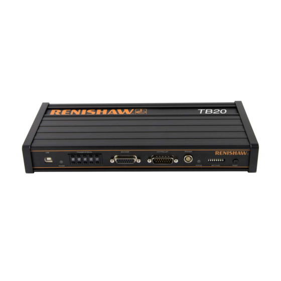
System System Configuration Data Capture Data Analysis Diagnostics Specifications TB20 interface USB port Power LED Trigger interval switches Encoder port Controller port Trigger port Status LED Configuration switches Reset switch TB20 quadrature trigger box www.renishaw.com/tb20... -
Page 11: Tb20 Configurations
System Configuration Configuration Data Capture Data Analysis Diagnostics Specifications TB20 configurations Open loop Closed loop TB20 quadrature trigger box www.renishaw.com/tb20... -
Page 12: Test Overview
Data Analysis Diagnostics Specifications Test overview XL-80 set-up * Set-up TB20 set-up Trigger interval set-up Configuration Switch set-up Data capture Capture Data analysis NOTE: * For XL-80 set-up procedure, please refer to XL-80 user guide F-9908-0683. TB20 quadrature trigger box www.renishaw.com/tb20... -
Page 13: Tb20 Set-Up
Connect the trigger port on TB20 to auxiliary I/O connector on the XL laser Configure switch settings Connect the USB power supply to the electrical outlet NOTE: For TB20 encoder and controller port pin-outs refer to Appendix A� TB20 quadrature trigger box www.renishaw.com/tb20... -
Page 14: Trigger Interval Set-Up
Trigger interval set-up To configure the trigger interval on the TB20 the ‘trigger interval’ switch is used. The input is a decimal value (“00000” is not permitted). The values for this switch can be set by reference to the table below or by calculation on the following page. - Page 15 Data Analysis Diagnostics Specifications Trigger interval set-up For custom trigger interval use the calculation: TB20 setting (in decimal) = desired trigger interval (microns) 2 × encoder resolution (microns) Where the encoder resolution is defined as: RS422 digital quadrature Analogue quadrature...
-
Page 16: Switch Set-Up
Data Capture Data Analysis Diagnostics Specifications Switch set-up The TB20 must be configured to specify the type of encoder connected and the type of trigger required. This is achieved using the ‘configuration switches’. Switch number 6,7,8 Function Trigger direction Encoder type... -
Page 17: Data Capture
Data Capture Data Analysis Diagnostics Specifications Data capture Two types of data capture can be achieved with TB20 using the XL-80 TPin function: • Quasi-static – the bed moves via predefined intervals and stops for the measurement to be taken. -
Page 18: Data Capture Reset Button
The ‘RESET’ button provides the following functionality: • Datum and capture the first point at the beginning of a test. • Clear any error conditions logged by the TB20 (providing the source of the error has been removed). • Update any changes to switch configurations. -
Page 19: Quasi-Static Data Capture Using Carto Capture
System Configuration Data Capture Data Capture Data Analysis Diagnostics Specifications Quasi-static data capture using CARTO Capture For full details on Capture please refer to the CARTO Capture user guide (Renishaw product no. F-9930-1007). TB20 quadrature trigger box www.renishaw.com/tb20... -
Page 20: Dynamic Data Capture Using Laserxl Dynamic Measurement
Configuration Data Capture Data Capture Data Analysis Diagnostics Specifications Dynamic data capture using LaserXL dynamic measurement For full details on Dynamic data capture and analysis please refer to the LaserXL manual (Renishaw product no. M-9908-9137). TB20 quadrature trigger box www.renishaw.com/tb20... -
Page 21: Data Analysis
Data analysis NOTE: For full details on Explore please refer to the CARTO Explore user guide (Renishaw product no. F-9930-1008). Dynamic data capture currently On completion of the test select ‘Analyse’ to launch Explore. not supported in CARTO. Please refer to XCal-View data analysis software. -
Page 22: Diagnostics
TB20 and encoder powered by an external USB power supply Green If controller port is attached to the controller, the TB20 is powered from the USB power supply and encoder from the controller Blue TB20 and encoder powered by the controller... -
Page 23: Status Led
Data Capture Data Analysis Diagnostics Diagnostics Specifications Diagnostics Status LED This LED provides the current status of the TB20. LED status Description Green Referenced - normal operating mode. Trigger green Trigger pulse is generated, green LED alternates between green and grey Not referenced –... -
Page 24: System Specifications
TB20 current 250 mA (with no encoder connected) requirement Encoder power 5 Vdc ±5%, capable of providing 500 mA current to encoder supply Encoder and 15-way D-type controller connectors Safety standard EN (IEC) 62368-1:2014+A11:2017 TB20 quadrature trigger box www.renishaw.com/tb20... -
Page 25: Encoder Types Supported
Configuration Data Capture Data Analysis Diagnostics Specifications Specifications Encoder types supported TB20 is compatible with analogue and digital quadrature encoders that require a 5V power supply. It supports: • Analogue 1 Vpp encoder • Analogue microcurrent encoder • Digital encoder NOTE: Refer to the encoder manufacturers installation manual for cabling and shielding recommendations. -
Page 26: Environment
-20 ˚C to 70 ˚C Maximum velocities The maximum velocity for analogue encoder applications is 1 m/s. Digital encoder velocities are as follows: Resolution Velocity m / s 0�05 µm 0�5 0�1 µm 0�5 µm TB20 quadrature trigger box www.renishaw.com/tb20... -
Page 27: Weights And Dimensions
System Configuration Data Capture Data Analysis Diagnostics Specifications Specifications Weights and dimensions Weight TB20: complete kit 1 kg 294 mm TB20 quadrature trigger box www.renishaw.com/tb20... -
Page 28: Wiring
5 V ±0.5 V maximum. The controller supply should be limited to a maximum output of 6.5 V. Voltage transients above this could cause permanent damage to the encoder. It is recommended that the encoder is never hot-swapped without removing the power from the TB20. Alternatively, if an unsensed supply is used, connect 0 V to 0 V link at the TB20. -
Page 29: Accuracy
For full details please refer to the XL-80 user guide (Renishaw product no. F-9908-0683). Delays in open loop TB20 introduces a delay in the encoder quadrature signals being received by the controller as per the table below: Quadrature input – trigger delay Effect on accuracy at different speeds (µm) -
Page 30: Accuracy - Delays In Closed Loop
Specifications Appendix B Accuracy - Delays in closed loop Quadrature output – trigger delay. The quadrature signals are regenerated inside the TB20 to be terminated to the machine controller. Effect on accuracy at different speeds (µm) Encoder type Delay (µs) 0.25 m/s... - Page 31 +44 (0) 1453 524524 uk@renishaw.com © 2017–2022 Renishaw plc. All rights reserved. This document may not be copied or reproduced in whole or in part, or transferred to any other WHILE CONSIDERABLE EFFORT WAS MADE TO VERIFY THE ACCURACY OF THIS media or language by any means, without the prior written permission of Renishaw.
Need help?
Do you have a question about the TB20 and is the answer not in the manual?
Questions and answers