
Related Manuals for Rockwell Automation Allen-Bradley 1441-DYN25-MBAL


Summary of Contents for Rockwell Automation Allen-Bradley 1441-DYN25-MBAL
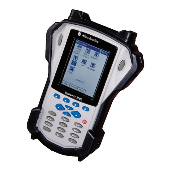
- Page 1 User Manual Balancing Extension Module for the Dynamix 2500 Data Collector Catalog Number 1441-DYN25-MBAL...
- Page 2 In no event will Rockwell Automation, Inc. be responsible or liable for indirect or consequential damages resulting from the use or application of this equipment.
-
Page 3: Table Of Contents
How to Delete Stored Files ........64 Index Rockwell Automation Publication 1441-UM004A-EN-P - May 2011... - Page 4 Table of Contents Notes: Rockwell Automation Publication 1441-UM004A-EN-P - May 2011...
-
Page 5: Optional Extension Modules
The RUCD test records and analyzes data from intermittent events and transient vibration signals from non-steady state machines. Additional Resources on page 6 for a listing of available publications. (1) This is an activation license for the Dynamix 2500 data collector. Rockwell Automation Publication 1441-UM004A-EN-P - May 2011... -
Page 6: Additional Resources
Provides declarations of conformity, certificates, and other certification details. You can view or download publications at http://www.rockwellautomation.com/literature. To order paper copies of technical documentation, contact your local Allen-Bradley distributor or Rockwell Automation sales representative. Rockwell Automation Publication 1441-UM004A-EN-P - May 2011... -
Page 7: Install Extension Modules
1. Open the base cover at the bottom of the Dynamix 2500 data collector. 2. Place the extension module SD card contact side-up into the unit until it is firmly seated in place. 3. Close the base cover. Rockwell Automation Publication 1441-UM004A-EN-P - May 2011... - Page 8 7. Press F1 (Extn Mgr). The Extension Manager screen appears showing the current extension module installations. 8. Press 0 (Shift) to display the Install Extension function. 9. Press F2 (Install) to install the new extension module. Rockwell Automation Publication 1441-UM004A-EN-P - May 2011...
-
Page 9: Uninstall Extension Modules
1. Press 0 (Shift) from the Setup Utility screen to display the Extension Manager function. The Extension Manager function remains on the screen for about three seconds after releasing 0 (Shift). Extension Manager 2. Press F1 (Extn Mgr). Rockwell Automation Publication 1441-UM004A-EN-P - May 2011... - Page 10 3. Select the extension module you want to uninstall and press F3 (Select). F3 (Select) toggles the selection on and off. A checkmark appears next to that extension module. 4. Press F1 (Uninstall). Rockwell Automation Publication 1441-UM004A-EN-P - May 2011...
- Page 11 6. Press F2 (Yes) to uninstall the extension module. 7. Press F4 (Esc) to exit the Extension Manager screen. Rockwell Automation Publication 1441-UM004A-EN-P - May 2011...
-
Page 12: Manage Extension Modules
The F2 (Hide) toggles between Hide and Show depending if the selected extension module is hidden or not. You have to exit and re-enter the Extension Manager after hiding an extension module to have the Show function appear. Rockwell Automation Publication 1441-UM004A-EN-P - May 2011... -
Page 13: Extension Module Battery Status Indicators
Table 1 - Extension Module Battery Icon Descriptions Battery Icon Meaning Battery status is good: >30% life remaining. Battery status is low: >10% life remaining. Battery status is very low: <10% life remaining. Battery is charging. Rockwell Automation Publication 1441-UM004A-EN-P - May 2011... - Page 14 Chapter 3 Installing Optional Extension Modules Notes: Rockwell Automation Publication 1441-UM004A-EN-P - May 2011...
- Page 15 You can use the internal laser tachometer in the data collector or an external laser tachometer, optical tachometer, or strobescope for measuring phase during the balance run. Rockwell Automation Publication 1441-UM004A-EN-P - May 2011...
-
Page 16: Balancing Measurements
With the machine stopped, set up the balancing equipment and mark your tachometer reference point on the rotor or shaft. Set Up the Balancing Parameters on page 20 to configure balancing measurement parameters for the balancing run sequence. Rockwell Automation Publication 1441-UM004A-EN-P - May 2011... - Page 17 • If further balancing is necessary, it automatically applies the influence coefficient to calculate additional trim weights that can be added to further balance the machine. Rockwell Automation Publication 1441-UM004A-EN-P - May 2011...
-
Page 18: Static-Couple Balancing
In as such, on the data collector, the static-couple procedure is identical to the two-plane procedure except the Correction Weight and Trim Weight screens show three correction weights for the static-couple procedure: • One weight for end plane 1 • One weight for end plane 2 Rockwell Automation Publication 1441-UM004A-EN-P - May 2011... - Page 19 Two Plane Balancing on page 45 on how to perform a two- plane Procedure section for details. Rockwell Automation Publication 1441-UM004A-EN-P - May 2011...
-
Page 20: Set Up The Balancing Parameters
• Review Review Data screen where you can review previously stored measurements or resume a previous balance measurement from the last completed run. Rockwell Automation Publication 1441-UM004A-EN-P - May 2011... -
Page 21: Balance Setup Screen
4. Press the Left arrow to save your selection. Use the descriptions in Balance Extension Module Parameters to help you configure the parameters in the Balance Setup screen. 5. Save the setup or start taking the balancing measurement. Rockwell Automation Publication 1441-UM004A-EN-P - May 2011... - Page 22 The options available in the list vary depending on the transducer selected. Weight Units Defines the units used in balancing. Specify the units of measurement used for your trial, correction, and trim weights. oz (default) Rockwell Automation Publication 1441-UM004A-EN-P - May 2011...
- Page 23 Sets the high pass filter to. apply to the measurement. The high pass filter is useful in removing high vibration, low 2 Hz (default) frequency signal components, which can dominate the signal. 10 Hz Rockwell Automation Publication 1441-UM004A-EN-P - May 2011...
- Page 24 ° planes 1 and 2, with a phase angle of 180 difference. The Static part of the solution will be calculated at the center between planes 1 and 2. Rockwell Automation Publication 1441-UM004A-EN-P - May 2011...
- Page 25 Posn 1 Offset Applies to Fixed weight position measurements only. ° 0 to 360 ° Enter the fixed position 1 offset, from zero to 360 , relative to the trigger reference. Rockwell Automation Publication 1441-UM004A-EN-P - May 2011...
-
Page 26: Single Plane Balancing
Add the Correction Weight and Take a Residual Measurement on page Split the Correction Weight on page Modify the Radius on page Add or Remove Weight on page Take the Residual Measurement on page Rockwell Automation Publication 1441-UM004A-EN-P - May 2011... -
Page 27: Take The Initial Vibration Measurement
5. Press Enter to take the initial vibration measurement. Depending on your setup, the Dynamix 2500 data collector may ask if the transducer is attached to plane 1. If the transducer is attached, press F4 (OK). Rockwell Automation Publication 1441-UM004A-EN-P - May 2011... -
Page 28: Add The Trial Weight
The Add Trial Weight screen appears when the initial run measurement is complete. You can manually enter the trial weight, the angle, and the radius, or you can have the data collector automatically estimate the trial weight for you. Rockwell Automation Publication 1441-UM004A-EN-P - May 2011... -
Page 29: Enter The Trial Weight Manually
Movement parameter in the Balance Setup screen. Set Up the Balancing Parameters on page 20 for additional information. 4. In the Radius parameter, enter the radius of the trial weight. 5. Press OK. Rockwell Automation Publication 1441-UM004A-EN-P - May 2011... -
Page 30: Estimate The Trial Weight
Use total rotor mass for single plane and 50% of mass for two plane. 4. Press F2 (OK). You are returned to the Add Trial Weight screen where the estimated trial weight displays in both the Mass and Estimated Mass fields. Rockwell Automation Publication 1441-UM004A-EN-P - May 2011... - Page 31 Move Around in a Balance Run on page 60 for details. • Press F2 (Summary) to display the results in the Vibration Summary Table. Review Balancing Measurements on page 63 for details. Rockwell Automation Publication 1441-UM004A-EN-P - May 2011...
-
Page 32: Take A Trial Run Weight Measurement
• The Trial Run magnitude is between 70% and 130% of the Initial Run magnitude, and the Trial Run phase is within ±30 of the Initial Run phase, the 30/30 rule is not being met, this warning appears: Rockwell Automation Publication 1441-UM004A-EN-P - May 2011... - Page 33 6. Select No, as you typically plan to remove the temporary trial weight (or select Yes if you plan to leave the trial weight attached). Rockwell Automation Publication 1441-UM004A-EN-P - May 2011...
- Page 34 8. Stop the machine, remove the temporary trial weight, and securely attach the permanent correction weight at the precise angle and radius specified. Rockwell Automation Publication 1441-UM004A-EN-P - May 2011...
-
Page 35: Take A Correction Run
You are prompted whether you wish to perform7 a trim run. The data collector automatically measures the speed, vibration, and phase. The values are constantly updated on the screen. 2. If necessary, press Yes to proceed with a trim run. Rockwell Automation Publication 1441-UM004A-EN-P - May 2011... - Page 36 The Trim 1 Weight – Solution screen displays the trim weight mass, angle, and radius to help balance the residual. 4. Stop the machine and securely attach the permanent trim weight at the precise angle and radius specified. Rockwell Automation Publication 1441-UM004A-EN-P - May 2011...
-
Page 37: Perform A Trim Run
The Summary function button is available from all balancing screens. 4. Press F2 (Summary) to display your procedure’s Vibration Summary Table. The Vibration Summary Table screen displays all magnitude and phase values for each run performed during your balancing procedure. Rockwell Automation Publication 1441-UM004A-EN-P - May 2011... - Page 38 After your balancing runs, you may want to combine your correction and trim weights into a single weight. Follow these steps to access the combine weights screen. 1. From the Weights Summary Table, press F2 (Comb Wt.). Rockwell Automation Publication 1441-UM004A-EN-P - May 2011...
- Page 39 3. After selecting all the weights you wish to combine into one, press F2 (Accept) to compute your combined weight. You are prompted whether you wish to remove all selected weights and combine with one weight? 4. Press F2 (Yes) to proceed. Rockwell Automation Publication 1441-UM004A-EN-P - May 2011...
- Page 40 6. Press F4 (Esc) to return to previous screens. 7. Remove the weights specified for removal, and attach the final combined weight at the precise angle and radius specified. Rockwell Automation Publication 1441-UM004A-EN-P - May 2011...
-
Page 41: Add The Correction Weight And Take A Residual Measurement
Additionally, the Dynamix 2500 data collector calculates the amount of weight that might be removed if weights are already attached to the rotor. When you need to save the Correction Weight solution, press F3 (Memory. Rockwell Automation Publication 1441-UM004A-EN-P - May 2011... - Page 42 Follow these instructions to take a residual measurement. 1. Attach the correction weight to the rotor. 2. Start the machine and let it reach operating speed. 3. Press Enter to take a residual measurement. Rockwell Automation Publication 1441-UM004A-EN-P - May 2011...
- Page 43 6. Shut down the machine and attach the trim weight(s) whose weight, angle, and radius are indicated on the screen. Do not remove the original correction weight. IMPORTANT 7. Start the machine and let it reach operating speed. 8. Press Enter. Rockwell Automation Publication 1441-UM004A-EN-P - May 2011...
- Page 44 However, if the vibration has been reduced to an acceptable level, balancing is complete. 9. Save your balancing data, if desired, by pressing F3 (Memory). Save a Balance Measurement on page 61 for details. Rockwell Automation Publication 1441-UM004A-EN-P - May 2011...
-
Page 45: Two Plane Balancing
Trim weights are added to the machine to cancel out the vibration measured during a residual measurement. Balancing Measurements on page 16 for details about these measurements. Rockwell Automation Publication 1441-UM004A-EN-P - May 2011... -
Page 46: Two Plane Balancing Procedure Overview
Setup options specific to two-plane procedures are detailed below. Single Plane Balancing on page 26 section for all other settings that apply to both single and two-plane balancing. Figure 1 - Balance Setup Screen with 2 Planes Selected. Rockwell Automation Publication 1441-UM004A-EN-P - May 2011... - Page 47 Plane 2 settings. • When two-plane balancing with one transducer, the Input Channel, Coupling, Sensitivity, and Input Range are set on Plane 1 and apply to both planes. Rockwell Automation Publication 1441-UM004A-EN-P - May 2011...
- Page 48 2. Select the type of coupling signal acquired for the transducers. • AC acquires the input signal from a buffered output (external) device. • ICP applies DC to the charge amplified transducers signal, and couples the dynamic signal to the input channel. Rockwell Automation Publication 1441-UM004A-EN-P - May 2011...
- Page 49 7. In the Position 1 Offset field, enter the fixed position 1 offset for the respective plane, from 0…360. Applies to Fixed weight position measurements only. 8. Press F3 (Start) or Enter to begin the two-plane balancing procedure. Rockwell Automation Publication 1441-UM004A-EN-P - May 2011...
-
Page 50: How To Perform Two-Plane Balancing
•Press 0 (Shift) and F1 (Go to) simultaneously to go back to a previous step in the balance run. Move Around in a Balance Run on page 60 for details. •Press F2 (Summary) to display the results in the Vibration Summary Table. Rockwell Automation Publication 1441-UM004A-EN-P - May 2011... - Page 51 Initial Run – Plane 1 screen displays the measurement results. If two transducers are used for the balancing, both planes appear simultaneously. You may skip to the next section. 4. Press Enter to proceed. Rockwell Automation Publication 1441-UM004A-EN-P - May 2011...
- Page 52 • Unless you wish the data collector to estimate a trial weight, the Radius entry is not necessary, so long as you position the trial, correction, and trim weights at the same radius. For more information, see Add the Trial Weight on page Rockwell Automation Publication 1441-UM004A-EN-P - May 2011...
- Page 53 Typically, select No, as you typically plan to remove the temporary trial weight (or select Yes if you plan to leave the trial weight attached). Rockwell Automation Publication 1441-UM004A-EN-P - May 2011...
- Page 54 The Trial Run 2 – Plane 1 screen displays. The Trial Run 2 – Plane 2 screen shows vibration magnitude and phase readings for Plane 2 with the trial weight on Plane 2. Rockwell Automation Publication 1441-UM004A-EN-P - May 2011...
- Page 55 Correction Weight – Solution screen, press Enter to begin the correction runs. You are prompted to verify the transducer is attached to the bearing closest to balancing Plane 1. 3. Verify the transducer and press Yes. Rockwell Automation Publication 1441-UM004A-EN-P - May 2011...
- Page 56 8. Verify whether the amount of residual unbalance is within specifications. 9. From the Correction Run – Plane 2 screen, press Enter. You are prompted whether you wish to trim the residual unbalance. Rockwell Automation Publication 1441-UM004A-EN-P - May 2011...
- Page 57 You can split the correction weight into two distinct angles, as well as modify the radius of the correction weight. Additionally, the Dynamix 2500 data collector calculates the amount of weight that might be removed if weights are already attached to the rotor. Rockwell Automation Publication 1441-UM004A-EN-P - May 2011...
- Page 58 4. Verify whether the amount of residual unbalance is within specifications. 5. From the Trim Run – Plane 1 screen, press Enter. You are prompted to verify the transducer is attached to the bearing nearest Plane 2. Rockwell Automation Publication 1441-UM004A-EN-P - May 2011...
- Page 59 When you press No to the Trim Residual prompt, the Vibration Summary Table automatically appears showing a summary of your measurement’s balancing data. Rockwell Automation Publication 1441-UM004A-EN-P - May 2011...
-
Page 60: Move Around In A Balance Run
Select the step that you want to return to, and press F2 (Go To pt). The data collector displays the selected screen. You can then retake a measurement, if necessary. Rockwell Automation Publication 1441-UM004A-EN-P - May 2011... -
Page 61: Saving, Loading, And Reviewing Balance Measurements
3. Modify the file name as necessary and press OK. You are returned to the Balance – Save Setup screen, which displays the new measurement’s filename and date. Rockwell Automation Publication 1441-UM004A-EN-P - May 2011... -
Page 62: Load A Previously Saved Setup
The Balance – Load Setup screen appears and lists of all your previously saved balance setups. 2. Select a file and press F3 (Open). 3. Press Enter to start the balancing measurement. The Initial Run screen appears. Rockwell Automation Publication 1441-UM004A-EN-P - May 2011... -
Page 63: Review Balancing Measurements
The Balance - Review Data screen appears. 2. Select a balance measurement and press F3 (Open). 3. The Go To screen appears. 4. Press the Up/Down arrows to select past data. 5. Press F2 (Go To Pt.). Rockwell Automation Publication 1441-UM004A-EN-P - May 2011... -
Page 64: How To Delete Stored Files
2. Press 0 to display a second set of functions. 3. Press F4 (Delete). You are prompted to confirm the deletion. 4. Press Yes and the file is deleted from the data collector. Rockwell Automation Publication 1441-UM004A-EN-P - May 2011... - Page 65 Add Trial Weight screen 28 Balance Setup screen 21 Correction Weight - Solution screen 41 measurments 16 two plane balancing 45 moving around 60 retaking measurement 60 battery status icons 13 uninstall extension module 9 Rockwell Automation Publication 1441-UM004A-EN-P - May 2011...
- Page 66 Index Notes: Rockwell Automation Publication 1441-UM004A-EN-P - May 2011...
- Page 68 Rockwell Automation representative. New Product Satisfaction Return Rockwell Automation tests all of its products to ensure that they are fully operational when shipped from the manufacturing facility. However, if your product is not functioning and needs to be returned, follow these procedures.
Need help?
Do you have a question about the Allen-Bradley 1441-DYN25-MBAL and is the answer not in the manual?
Questions and answers