Advertisement
Quick Links
MANUFACTURED BY:
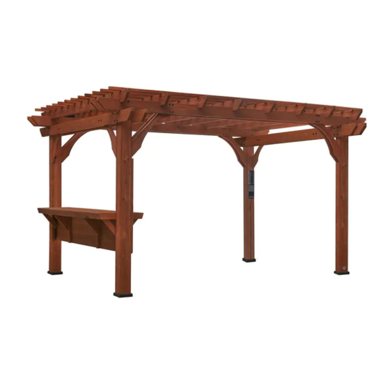
14 x 10 SILVERTON PERGOLA
Backyard Discovery
3305 Airport Drive
Pittsburg, KS 66762
Model # 19065
Owner's Manual & Assembly Instructions
800-856-4445
Before you begin
average 2 person assembly time
FOR QUICK &
EASY ASSEMBLY
8
FIND 3D INSTRUCTIONS
FOR THIS PRODUCT IN
DOWNLOAD THE FREE APP
assembly time may vary based on skill level
For the most up to date assembly manual,
to register your set, or to order replacement parts please visit
www.backyarddis overy.com
SAVE THIS ASSEMBLY MANUAL FOR FUTURE REFERENCE IN THE
EVENT THAT YOU NEED TO ORDER REPLACEMENT PARTS.
Para obtener instrucciones en español, visite www.backyarddiscovery.com
Made in China | INS-19065
-A-SILVERTON 14 x 10 PERGOLA-ENG
Advertisement

Related Manuals for Backyard Discovery 1906549


Summary of Contents for Backyard Discovery 1906549
- Page 1 MANUFACTURED BY: 14 x 10 SILVERTON PERGOLA Backyard Discovery 3305 Airport Drive Pittsburg, KS 66762 Model # 19065 Owner’s Manual & Assembly Instructions 800-856-4445 Before you begin average 2 person assembly time FOR QUICK & EASY ASSEMBLY FIND 3D INSTRUCTIONS...
- Page 2 INSTALLATION SERVICES AVAILABLE! Need a helping hand? Let our team of professionals handle the installation for you! *Installation services are only available to U.S. customers. With Go Configure, we bring you 18 years of experience right to your doorstep. We service a wide array of indoor and outdoor recreation products that most consumers don’t have the time or ability to deliver &...
- Page 3 Owner’s Manual Please Read This Before Starting Assembly MISSING A PART? CALL US BEFORE GOING BACK TO THE STORE The store where you made your purchase does not stock parts for this item. If you have assembly questions or you are missing or have damaged parts, please call 1-800-856-4445 or visit www.backyarddiscovery.com...
-
Page 4: Limited Warranty
Botanical, Adventure Playsets, and Leisure Time Products. Backyard Discovery warrants that this product is free from defect in materials and workmanship for a period of one (1) year from the original date of purchase. This one (1) year warranty covers all parts including wood, hardware, and accessories. All wood carries a five (5) year pro-rated warranty against rot and decay. Refer to the schedule below for charges associated with replacement of parts under this Limited Warranty. - Page 5 Owner’s Manual Safety Warnings and Maintenance Instructions WARNING IT IS IMPORTANT TO CHECK AND TIGHTEN ALL HARDWARE AT THE BEGINNING AND DURING THE SEASON AS THEY MAY LOOSEN DUE TO WOOD EXPANSION AND CONTRACTION. • DO NOT climb or walk on the roof for any reason •...
- Page 6 About Our Wood Backyard Discovery uses 100% Cedar (C. Lanceolata) wood. Although we take great care in selecting the best quality lumber available, wood is still a product of nature and susceptible to weathering which can change the appearance of your set.
- Page 7 Owner’s Manual Assembly Tips Protrusion Hazard Incorrect Correct If you see exposed If you see exposed threads and your bolt threads and your bolt protrudes beyond the protrudes beyond the T-Nut you may have over T-Nut you may have over tightened the bolt or tightened the bolt or used incorrect hardware.
-
Page 8: Assembly Tips
Assembly Tips ASSEMBLY TIP: Keep an eye out for these boxes which will contain helpful pictures and information making the assembly process as quick and painless as possible. Sorting Wood When removing the wood from the boxes we recommend arranging them by part number before you begin assembly. - Page 9 Owner’s Manual Tools Required for Installation (Square) (Level 24") (Phillips Screw Driver) (Tape Measure) (Rubber Mallet - Optional) (Drill Attachments: Phillips (3/16" Concrete (Cordless Drill or Electric Drill) Head, 1/4" & 5/16"Socket Drill Bit) Drivers) (Claw Hammer) (An Adult w/ an Adult Helper) (Ladder)(2)
- Page 10 Owner’s Manual Owner’s Manual Basic Setup Dimensions & Assembly Notes Tools Required for Installation It is critically important that you start with square and level footings, concrete pad or deck to attach your structure • Pay close attention to the items needed for each step. Make sure you are using the correct hardware for each step. Using incorrect hardware may result in improper assembly.
- Page 11 Important Note: Parts Identification Wood Components (NOT TO SCALE) D1 - JOIST - W4L12593 (10) 1 3/8"x5 1/4"x114" (36x134x2895) D2 - JOIST - W4L12588 1 3/8"x5 1/4"x87 3/4" (36x134x2228) D3 - JOIST - W4L12587 1 3/8"x5 1/4"x27 1/2" (36x134x700) D4 - JOIST - W4L12586 1 3/8"x5 1/4"x96"...
- Page 12 Important Note: Parts Identification Wood Components (NOT TO SCALE) PT1 - PERGOLA POST - W2A02814 5 1/2"x5 1/2"x89 9/16"(140x140x2275) PT2 - PERGOLA POST - W2A02809 5 1/2"x5 1/2"x89 9/16"(140x140x2275) PT3 - PERGOLA POST - W2A02815 5 1/2"x5 1/2"x89 9/16"(140x140x2275) PT4 - PERGOLA POST - W2A02810 5 1/2"x5 1/2"x89 9/16"(140x140x2275) TT1 - INSIDE TABLE TOP ASSEMBLY - W2A02812 2 3/8"x13 3/8"x84 7/8"...
- Page 13 Important Note: Backyard Discovery recommends taking all the hardware out of the box and arranging them by type before you begin assembly. This will allow for faster assembly and easy identification of any hardware that may be missing or damaged so they can be replaced before assembly.
- Page 14 Important Note: Backyard Discovery recommends taking all the hardware out of the box and arranging them by type before you begin assembly. This will allow for faster assembly and easy identification of any hardware that may be missing or damaged so they can be replaced before assembly.
- Page 15 Parts Identification Accessories (NOT TO SCALE) HT - FOOT 142 SQUARE POST - A100029 - BYD ID TAG (SMALL) WITHOUT AGES - A100241 (1) STAIN MARKER - SANDALWOOD - A6P00322 - "A" REVISION TAG - A100314 (1) PERGOLA ELECTRICAL KIT - A6P00265 - PATENT PENDING - 1"...
- Page 16 Z1 - JOIST - W4L12589 1 3/8"x6 1/4"x96 1/8" (36x157x2443) STEP 1 COMPLETE THIS STEP TWICE BOLT WH TIP: BARREL (12) 5/16x1 BLK FOR EASE OF ASSEMBLY WE RECOMMEND (12) WH 5/16x7/8 H100468 USING SAW HORSES FOR STEPS THROUGH H100192 BOLT WH 5/16x1 BLK (6 PLCS) WASHER...
- Page 17 Z2 - JOIST - W4L12592 1 3/8"x6 1/4"x96 1/8" (36x157x2443) STEP 2 COMPLETE THIS STEP THREE TIMES BOLT WH BARREL (18) 5/16x1 BLK (18) WH 5/16x7/8 H100468 H100192 WASHER WASHER WASHER LOCK EXT 12x19 BLK LOCK EXT LOCK EXT (18) (18) (6 PLCS) 12x19 BLK...
- Page 18 D2 - JOIST - W4L12588 1 3/8"x5 1/4"x87 3/4" (36x134x2228) D3 - JOIST - W4L12587 D6 - LONG ANGLE BRACE - W4L12590 1 3/8"x5 1/4"x27 1/2" (36x134x700) 1 3/8"x5 1/4"x36 3/4" (36x134x933) COMPLETE THIS STEP TWICE STEP 3 BOLT WH BARREL 5/16x2-1/4 (16)
- Page 19 PT1 - PERGOLA POST - W2A02814 5 1/2"x5 1/2"x89 9/16"(140x140x2275) D5 - SHORT ANGLE BRACE - W4L12591 1 7/16"x5 1/4"x33 5/8" (36x134x854) PT2 - PERGOLA POST - W2A02809 5 1/2"x5 1/2"x89 9/16"(140x140x2275) D4 - JOIST - W4L12586 1 3/8"x5 1/4"x96" (36x134x2438) STEP 4 BOLT WH WASHER...
- Page 20 D5 - SHORT ANGLE BRACE - W4L12591 1 7/16"x5 1/4"x33 5/8" (36x134x854) PT3 - PERGOLA POST - W2A02815 5 1/2"x5 1/2"x89 9/16"(140x140x2275) D4 - JOIST - W4L12586 1 3/8"x5 1/4"x96" (36x134x2438) PT4 - PERGOLA POST - W2A02810 5 1/2"x5 1/2"x89 9/16"(140x140x2275) STEP 5 BOLT WH SCREW WH...
- Page 21 JOIST ASSEMBLY FROM STEP 3 STEP 6 BOLT WH 5/16X6 BLK BOLT WH 5/16X6 BLK H100363 (4 PLCS) WASHER LOCK EXT 8x19 BLK WASHER LOCK EXT (4 PLCS) SCREW WH 8x19 BLK 5/16x3 1/2 H100198 WASHER LOCK EXT 12x19 BLK (4 PLCS) H100482 BARREL...
- Page 22 ARCH JOIST ASSEMBLY FROM STEP 1 F1 - SPACER - W4L12594 1 3/8"x2"x5 1/2" (36x50x140) STEP 7 NUT BARREL WH 5/16x1 1/2 (8 PLCS) WASHER WASHER LOCK EXT 12x19 BLK LOCK EXT (8 PLCS) 8x19 BLK H100198 NOTE & ALIGN WASHER PILOT HOLES LOCK EXT...
- Page 23 - 1" ANGLE BRACKET - A4M00987 STEP 8 SCREW PWH 8x1-1/4 (40) H100536 SCREW PWH 8x1-1/4 BLK (40 PLCS) 1" ANGLE BRACKET NOTE: BRACKET SHOULD BE CENTERED OVER JOINT AS SHOWN 1" ANGLE BRACKET 1" ANGLE BRACKET 1" ANGLE BRACKET...
- Page 24 CENTER ARCH JOIST ASSEMBLY FROM STEP 2 STEP 9 NOTE PILOT HOLES. ALIGN PILOT HOLES AND MOVE ON TO STEP 10 CENTER ARCH JOIST ASSEMBLY (3 PLCS)
- Page 25 D1 - JOIST - W4L12593 (10) 1 3/8"x5 1/4"x114" (36x134x2895) STEP 10 SCREW WH SCREW WH (44) 5/16x5-1/2 5/16x8 BLK WASHER LOCK EXT 8x19 BLK H100766 (50 PLCS) H100204 LAG SCREW WH 5/16x5-1/2 BLK (44 PLCS) LAG SCREW WH 5/16x8 BLK WASHER (3 PLCS) LOCK EXT...
- Page 26 WP1 - WALL PANEL - W2A02813 2 1/2"x15 15/16"x84 7/8" (65x405x2156) STEP 11 SCREW WH 1/4x1-1/2 H100403 LINE UP PILOT HOLES IN PANEL WITH PILOT HOLES IN POST AND ATTACH. LAG SCREW WH 1/4x1-1/2 in (8 PLCS)
- Page 27 F4 - TABLE BRACE - W4L12600 F2 - TABLE BRACE - W4L12595 1 3/8"x2 3/8"x11 7/8" (36x60x303) 1 3/8"x2 3/8"x11 7/8" (36x60x303) STEP 12 SCREW WH 1/4x2-1/2 H100456 NOTE PILOT HOLE. WASHER LOCK EXT 6x15 BLK H100405 WASHER LOCK EXT 6x15 BLK (2 PLCS) LAG SCREW WH 1/4x2-1/2 BLK (2 PLCS)
- Page 28 TT2 - OUTER TABLE TOP ASSEMBLY - W2A02811 2 3/8"x14 5/16"x84 7/8" (60x364x2156) STEP 13 SCREW WH 1/4x4 BLK H100564 LAG SCREW WH 1/4x4 BLK (2 PLCS) SCREW WH WASHER 1/4x2-1/2 LOCK EXT 6x15 BLK WASHER LOCK EXT 6x15 BLK H100456 H100405 (2 PLCS)
- Page 29 F3 - TABLE BRACE - W4L12598 1 3/8"x2 3/8"x12 13/16" (36x60x325) STEP 14 SCREW WH 1/4x2-1/2 H100456 NOTE PILOT HOLE. WASHER LOCK EXT 6x15 BLK H100405 LAG SCREW WH 1/4x2-1/2 BLK (2 PLCS) WASHER LOCK EXT 6x15 BLK (2 PLCS)
- Page 30 TT1 - INSIDE TABLE TOP ASSEMBLY - W2A02812 2 3/8"x13 3/8"x84 7/8" (60x340x2156) STEP 15 SCREW WH 1/4x4 BLK H100564 SCREW WH WASHER 1/4x2-1/2 LOCK EXT 6x15 BLK H100456 H100405 SCREW PFH 8X1-1/2 BLK H100200 SCREW PFH 8X1-1/2 BLK (8 PLCS) LAG SCREW WH 1/4x4 BLK (2 PLCS) WASHER LOCK EXT 6x15 BLK...
- Page 31 G1 - TABLE BRACE - W4L12596 1"x5 1/4"x16 5/8" (24x134x423) STEP 16 WASHER BOLT WH SCREW PFH 8X1-1/2 BLK LOCK EXT 1/4x2-1/4 (9 PLCS) 6x15 BLK H100405 H100567 SCREW PFH T-NUT 1/4 8X1-1/2 BLK H100200 H100398 BOLT WH 1/4x2 1/4 BLK (3 PLCS) WASHER LOCK EXT 6x15 BLK (3 PLCS)
- Page 32 G2 - TABLE BRACE - W4L12597 1"x5 1/4"x16 5/8" (24x134x423) STEP 17 BOLT WH WASHER 1/4x2-1/4 LOCK EXT 6x15 BLK H100567 SCREW PFH 8X1-1/2 BLK H100405 (9 PLCS) T-NUT 1/4 SCREW PFH 8X1-1/2 BLK H100398 H100200 NOTE PILOT HOLE BOLT WH 1/4x2 1/4 BLK (3 PLCS) T-NUT 1/4 BLK (3 PLCS)
-
Page 33: Left Side
- BYD ID TAG (SMALL) WITHOUT AGES - A100241 - "A" REVISION TAG - A100314 STEP 18 SCREW LEFT SIDE PWH 8x3/4 H100392 SCREW PWH 8x3/4 BLK (2 PLCS) "A" REVISION TAG 3 7/8 in [100 mm] RIGHT SIDE SCREW PWH 8x3/4 BLK (2 PLCS) BYD ID TAG (SMALL) WITHOUT AGES... - Page 34 HT - FOOT 142 SQUARE POST - A100029 STEP 19 DECIDE WHERE TO PLACE THE PERGOLA. NOTE THIS MOUNTING PROCEDURE IS MEANT TO BE USED ON CONCRETE ONLY. PLACE THE PERGOLA EXACTLY WHERE IT WILL BE ANCHORED WHEN COMPLETED AND SLIDE A FOOT UNDER EACH POST.
- Page 35 STEP 20 USE CHALK TO TRACE AROUND THE EDGES OF EACH FOOT.
- Page 36 STEP 21 MOVE THE PERGOLA ASIDE. PLACE EACH FOOT INSIDE OF THE LINES DRAWN IN THE PREVIOUS STEP. USING A 3/16" CONCRETE DRILL BIT, PILOT DRILL ATTACHMENT HOLES INTO THE CONCRETE PAD. NEXT, USE THE 1/4"x2" CONCRETE ANCHORS TO ATTACH EACH FOOT TO THE CONCRETE SURFACE.
- Page 37 STEP 22 SCREW PFH MOVE THE PERGOLA BACK IN TO PLACE, SETTING EACH POST INSIDE A FOOT (16) 8X1-1/2 BLK AND MOUNT. H100200 SCREW PFH 8X1-1/2 BLK (16 PLCS)
- Page 38 D7 - CORD COVER - W4L12599 1"x5 1/4"x51 5/8" (24x134x1310) (1) PERGOLA ELECTRICAL KIT - A6P00265 - PATENT PENDING STEP 23 PRESS THE ELECTRICAL CORD ASSEMBLY INTO THE SCREW PFH CUT OUTS ON THE D7 CORD COVER, AS SHOWN. 8X2-1/2 BLK H100201 SCREW PFH 8X2-1/2 BLK (8 PLCS)
- Page 39 - 90° L-BRACKET - BLK - A4M00555 STEP 24 PLACE L-BRACKETS NEXT TO THE CENTER BOLT AND MOUNT AS SHOWN. SCREW PWH 8x3/4 SCREW PWH 8x3/4 BLK H100392 (4 PLCS) 90° L-BRACKET - BLK (2 PLCS) NOTE L-BRACKET LOCATION...
Need help?
Do you have a question about the 1906549 and is the answer not in the manual?
Questions and answers