Advertisement
Quick Links
Basepoint Business Centre: Rivermead Drive,Westlea, Swindon SN5 7EX Phone: 0800-118-2476
J.P. Coenstraat 7, The Bridge, The Hague, 2595 WP, Netherlands Phone: 0800-567-8990
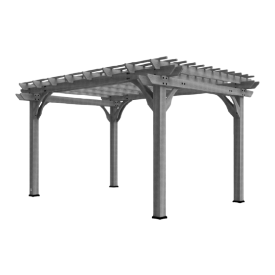
14x10 PERGOLA
Model # 1802513B
The assembly manual must be retained
since it contains important information
For the most up to date assembly manual, to register your set, or to order replacement parts
Para obtener instrucciones en español, visite www.backyarddiscovery.com
MANUFACTURED BY:
Backyard Discovery
3305 Airport Drive, Pittsburg, KS 66762
800-856-4445
Please visit www.backyarddiscovery.com
INS-1802513B-A-14x10 PERGOLA-ENG 1/19/24
Made in China
Advertisement

Related Manuals for Backyard Discovery 1802513B


Summary of Contents for Backyard Discovery 1802513B
- Page 1 Basepoint Business Centre: Rivermead Drive,Westlea, Swindon SN5 7EX Phone: 0800-118-2476 J.P. Coenstraat 7, The Bridge, The Hague, 2595 WP, Netherlands Phone: 0800-567-8990 14x10 PERGOLA Model # 1802513B The assembly manual must be retained since it contains important information Please visit www.backyarddiscovery.com For the most up to date assembly manual, to register your set, or to order replacement parts Para obtener instrucciones en español, visite www.backyarddiscovery.com...
- Page 2 Owner's Manual - Basic Setup Dimensions & Assembly Notes It is critically important that you start with square and level footings, concrete pad or deck to attach your structure Pay close attention to the items needed for each step. Make sure you are using the correct hardware for each •...
- Page 3 Owner's Manual - Anchoring Layout 90 in [2286 mm] 83 1/4 in [2116 mm] 138 in 155 1/2 in [3506 mm] [3950 mm] 131 3/8 in 164 3/4 in [3336 mm] [4185 mm] 6 3/4 in [170 mm] 4 ANCHORS PER POST...
- Page 4 Owner's Manual - Parts Identification Wood Components (Not to Scale) JOIST - W4L11635 (x2) 1 3/8"x5 1/4"x92 7/8" (36x134x2360) JOIST END - W4L11643 (x4) 1 3/8"x5 1/4"x37 1/2" (36x134x954) SLOTTED JOIST - W4L11637 (x8) 1 3/8"x5 1/4"x114" (36x134x2896) JOIST - W4L18489 (x2) 1 3/8"x5 1/4"x90"...
- Page 5 Owner's Manual - Parts Identification Wood Components (Not to Scale) JOIST - W4L11646 (x2) 1 3/8"x5 1/4"x92 7/8" (36x134x2360) PURLIN - W4L11639 1 3/8"x1 3/8"x69 5/8" (36x36x1767) (x12) PURLIN - W4L11640 1 3/8"x1 3/8"x90 1/4" (36x36x2291) (x12) PERGOLA POST - W2A03771 5 1/2"x5 1/2"x89 1/2"...
- Page 6 Owner's Manual - Parts Identification Hardware Components H100192 NUT BARREL WH (x40) H100198 WASHER LOCK H100199 WASHER LOCK 5/16x7/8 (x80) EXT BLK (x64) EXT BLK 8x19 12x19 H100193 NUT BARREL WH (x24) 5/16x1-1/2 H100405 WASHER LOCK EXT BLK (x12) H100392 SCREW PWH BLK H100120 SCREW...
- Page 7 Owner's Manual - Parts Identification Accessory Components (Not to Scale) A100029 FOOT 142 SQUARE POST (x4) A100241 BYD ID TAG (SMALL) WITHOUT AGES (x1) 9205413 ELECTRICAL ENCLOSURE (x1)
-
Page 8: Hardware Parts
PRE-ASSEMBLY STEP 1 - SORTING PARTS It is critical for ease of assembly that you take the time to sort and organize the wood and hardware. WOOD PARTS: • Organize wood parts by the three-digit, alpha-numeric number stamped on each board (ex. P01). •... - Page 9 PRE-ASSEMBLY STEP 2 - TOOLS REQUIRED Drill Attachments: Phillips Head Open End Wrenches 1/2" & 9/16" 1/8", 3/16", 3/8" & 7/16" Drill Bits 3/8" Drive Ratchet, 1/2" & 9/16" STD Sockets 1/2" & 9/16" Deep Sockets Phillips Screw Driver Cordless Drill or Electric Drill Rubber Mallet - Optional Claw Hammer...
- Page 10 PRE-ASSEMBLY STEP 3 - CHOOSE YOUR ASSEMBLY METHOD There are several types of assembly instructions available to you. 1. Printed Assembly Manual included with your set 2. BILT APP - 3D interactive instructions 3. Combination of the Printed Manual and BILT APP (Note: Step numbers can differ between the two methods)
- Page 11 STEP 1 - PERGOLA ASSEMBLY PART DESCRIPTION NUMBER H100192 NUT BARREL WH 5/16x7/8 BLK H100198 WASHER LOCK EXT 8x19 BLK SHORT ANGLE BRACE - W4L18491 H100199 WASHER LOCK EXT 12x19 BLK 1 3/8"x5 1/4"x26 5/8" (36x134x675) (x4) H100205 BOLT WH 5/16x2-1/4 BLK JOIST - W4L18489 1 3/8"x5 1/4"x90"...
- Page 12 STEP 2 - PERGOLA ASSEMBLY PART DESCRIPTION NUMBER H100192 NUT BARREL WH 5/16x7/8 BLK H100198 WASHER LOCK EXT 8x19 BLK H100199 WASHER LOCK EXT 12x19 BLK LONG ANGLE BRACE - W4L18490 JOIST END - W4L11643 1 3/8"x5 1/4"x33 1/2" (36x134x850) (x4) H100205 BOLT WH 5/16x2-1/4 BLK...
- Page 13 STEP 3 - PERGOLA ASSEMBLY PART DESCRIPTION NUMBER H100192 NUT BARREL WH 5/16x7/8 BLK H100198 WASHER LOCK EXT 8x19 BLK LONG ANGLE BRACE - W4L18490 JOIST END - W4L11634 H100199 WASHER LOCK EXT 12x19 BLK (x4) 1 3/8"x5 1/4"x33 1/2" (36x134x850) 1 3/8"x5 1/4"x37 1/2"...
- Page 14 STEP 4 - PERGOLA ASSEMBLY PART DESCRIPTION NUMBER H100193 NUT BARREL WH 5/16x1-1/2 BLK H100196 BOLT WH 5/16x7-1/4 BLK JOIST - W4L11638 1 3/8"x5 1/4"x90" (36x134x2286) (x2) H100198 WASHER LOCK EXT 8x19 BLK H100199 WASHER LOCK EXT 12x19 BLK H100405 WASHER LOCK EXT 6x15 BLK PERGOLA POST - W2A03771 H100792...
- Page 15 STEP 5 - PERGOLA ASSEMBLY PART DESCRIPTION NUMBER H100193 NUT BARREL WH 5/16x1-1/2 BLK H100196 BOLT WH 5/16x7-1/4 BLK H100198 WASHER LOCK EXT 8x19 BLK JOIST END - W4L11633 H100199 WASHER LOCK EXT 12x19 BLK 1 3/8"x5 1/4"x15" (36x134x381) (x8) REPEAT PROCESS FOR OPPOSITE SIDE.
- Page 16 STEP 6 - PERGOLA ASSEMBLY PART DESCRIPTION NUMBER H100193 NUT BARREL WH 5/16x1-1/2 BLK H100196 BOLT WH 5/16x7-1/4 BLK H100198 WASHER LOCK EXT 8x19 BLK H100199 WASHER LOCK EXT 12x19 BLK H100405 WASHER LOCK EXT 6x15 BLK H100792 LAG SCREW WH 1/4x3 BLK (x8) WASHER - 8x19 (x8)
- Page 17 STEP 7 - PERGOLA ASSEMBLY PART DESCRIPTION NUMBER H100198 WASHER LOCK EXT 8x19 BLK H100204 LAG SCREW WH 5/16x5-1/2 BLK SLOTTED JOIST - W4L11637 1 3/8"x5 1/4"x114" (36x134x2896) (x8) ALIGN JOIST OVER PILOT HOLES IN LOWER JOIST (x16) LAG SCREW - 5 1/2" (x16) (x8) WASHER - 8x19...
- Page 18 STEP 8 - PERGOLA ASSEMBLY PART DESCRIPTION NUMBER H100201 SCREW PFH 8x2-1/2 BLK PURLIN - W4L11639 1 3/8"x1 3/8"x69 5/8" (36x36x1767) (x12) PURLIN - W4L11640 (x12) 1 3/8"x1 3/8"x90 1/4" (36x36x2291) ASSEMBLE REMAINING P1 AND P2 PURLINS ALTERNATING LOCATIONS AS SHOWN. (x12) (x12) (x96)
- Page 19 STEP 9 - PERGOLA ASSEMBLY A100029 FOOT 142 SQUARE POST (x4) DECIDE WHERE TO PLACE THE PERGOLA; GRASS, CONCRETE OR OTHER MATERIAL. PLACE THE PERGOLA EXACTLY WHERE IT WILL BE ANCHORED WHEN COMPLETED AND SLIDE A FOOT UNDER EACH POST 'WP1'. NOTE: IF NOT PLACING ON CONCRETE, PROCEED TO STEP 13.
- Page 20 STEP 10 - PERGOLA ASSEMBLY USE CHALK TO TRACE AROUND THE EDGES OF EACH FOOT.
- Page 21 STEP 11 - PERGOLA ASSEMBLY PART DESCRIPTION NUMBER H100120 CONCRETE ANCHOR 1/4x2 MOVE THE PERGOLA ASIDE. PLACE EACH FOOT INSIDE OF THE LINES DRAWN IN STEP 14. USING A CONCRETE DRILL BIT, PILOT DRILL ATTACHMENT HOLES INTO THE CONCRETE PAD. NEXT, USE THE 1/4"x2"...
- Page 22 STEP 12 - PERGOLA ASSEMBLY SET THE PERGOLA BACK IN PLACE, SETTING EACH POST 'WP1' INSIDE AN FOOT.
- Page 23 STEP 13 - PERGOLA ASSEMBLY PART DESCRIPTION NUMBER H100200 SCREW PFH 8x1-1/2 BLK ATTACH FEET TO EACH 'WP1' POST USING 1-1/2" SCREWS INTO EACH SIDE OF FOOT, AS SHOWN. (x16) SCREW - 1 1/2"...
- Page 24 STEP 14 - PERGOLA ASSEMBLY PART DESCRIPTION NUMBER H100392 SCREW PWH 8x3/4 BLK BYD ID TAG A100241 (SMALL) (x1) WITHOUT AGES PLACE I.D. PLACARD ON FRONT OF POST APPROXIMATELY AS SHOWN. SQUARE POSTS AND TIGHTEN ALL HARDWARE AT THIS TIME. (x1) BYD ID TAG (SMALL) WITHOUT AGES 5 3/4 in...
-
Page 25: Electrical Enclosure
PowerPort 9205413 ELECTRICAL ENCLOSURE (x1) FOR POWERPORT INSTALLATION REFER TO ASSEMBLY INSTRUCTIONS THAT COME PACKAGED WITH THE POWERPORT KIT. INSTALL ON ANY POST THAT IS DESIRED. FOLLOW DIRECTIONS FOR PROPER INSTALLATION.
Need help?
Do you have a question about the 1802513B and is the answer not in the manual?
Questions and answers