Advertisement
Table of Contents
- 1 Table of Contents
- 2 Package Contents
- 3 Hardware Contents
- 4 Safety Information
- 5 Preparation
- 6 Initial Installation Instructions
- 7 Wiring Instructions
- 8 Final Installation Instructions
- 9 Operation Instructions
- 10 Care and Maintenance
- 11 Troubleshooting
- 12 Limited Lifetime Warranty
- 13 FCC Warning
- 14 Replacement Part List
- Download this manual
Harbor Breeze ® is a registered trademark
of LF, LLC. All Rights Reserved.
ATTACH YOUR RECEIPT HERE
Serial Number
Questions, problems, missing parts? Before returning to your retailer, call our customer
service department at 1-800-643-0067, 8 a.m. - 8 p.m., EST, Monday - Sunday.
VR20245
Purchase Date
1
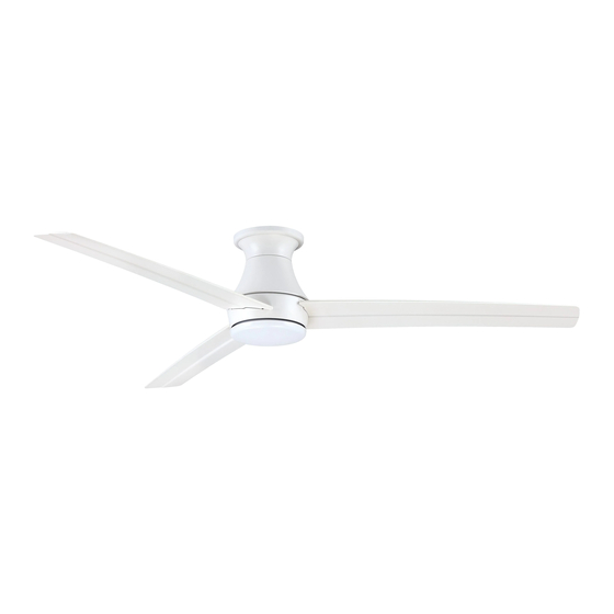
KENTON CEILING FAN
ITEM #2599777
MODEL #HTD20005
Español p. 18
Advertisement
Table of Contents

Subscribe to Our Youtube Channel
Related Manuals for Harbor Breeze HTD20005


Summary of Contents for Harbor Breeze HTD20005
- Page 1 ITEM #2599777 KENTON CEILING FAN MODEL #HTD20005 Harbor Breeze ® is a registered trademark Español p. 18 of LF, LLC. All Rights Reserved. ATTACH YOUR RECEIPT HERE Serial Number Purchase Date Questions, problems, missing parts? Before returning to your retailer, call our customer service department at 1-800-643-0067, 8 a.m.
-
Page 2: Table Of Contents
TABLE OF CONTENTS Package Contents ......................Hardware Contents ......................Safety Information ......................Preparation ........................Initial Installation Instructions ................... Wiring Instructions ......................Final Installation Instructions .................... Operation Instructions ...................... Care and Maintenance ..................... Troubleshooting ....................... Limited Lifetime Warranty ....................FCC Warning ……………....................Replacement Part List ...................... -
Page 3: Package Contents
PACKAGE CONTENTS CR2032 3V PART DESCRIPTION QUANTITY PART DESCRIPTION QUANTITY Trim Ring [Preassembled Ceiling Plate on Motor Assembly (B)] Mounting Screw Motor Assembly [Preassembled on Motor Assembly (B )] Mounting Plate Screw Switch Housing [Preassembled on Motor Assembly (B )] Switch Housing Screw Blade [Preassembled on Switch... -
Page 4: Hardware Contents
HARDWARE CONTENTS (not shown actual size) Blade Screw Qty 12+1 extra SAFETY INFORMATION READ AND SAVE THESE INSTRUCTIONS Please read and understand this entire manual before attempting to assemble, operate or install the product. . All electrical connections must comply with local codes, ordinances or the National Electric Code (NEC). Contact your municipal building department to inquire about your local codes, permits and/or inspections. -
Page 5: Preparation
WARNING Chemical Burn Hazard. Keep batteries away from children. This remote contains a lithium button cell battery. If a new or used lithium button/coin cell battery is swallowed or enters the body, it can cause severe internal burns and can lead to death in as little as 2 hours. Always completely secure the battery compartment. If the battery compartment does not close securely, stop using the product, remove the batteries, and keep it away from children. -
Page 6: Initial Installation Instructions
INITIAL INSTALLATION INSTRUCTIONS Turn off circuit breakers and wall switch to the fan supply line leads. Turn Off Power Source DANGER: Failure to disconnect power supply prior to installation may result in serious injury or death. 2. . Fan mounting option: This fan was designed to be mounted only on flat ceilings and can be used on ceilings less than 9 feet high (blades should be a minimum of 7 feet from the... - Page 7 INITIAL INSTALLATION INSTRUCTIONS Partially remove two diagonal mounting screws (I) on the round holes, keep for later use. And loosen the other two screws (I). Hang the motor assembly (B) onto the hook from the ceiling plate (A). This will allow for hands-free wiring.
-
Page 8: Wiring Instructions
WIRING INSTRUCTIONS WARNING: To avoid possible electrical shock, be sure electricity is turned off at the main fuse box before hanging. WARNING: If you are not sure if the outlet box is grounded, contact a licensed electrician for advice, as it must be grounded for safe operation. WARNING: If house wires are different colors than referred to in the following steps, stop immediately. -
Page 9: Final Installation Instructions
FINAL INSTALLATION INSTRUCTIONS 1. After wire connections, take the motor assembly (B) off the hook.Raise the motor assembly (B) up to the ceiling plate (A).Align two remained screws (I) on the motor assembly (B) to the keyholes on the ceiling plate (A), rotate clockwise until the screw heads engage the keyhole slots fully. - Page 10 FINAL INSTALLATION INSTRUCTIONS 4. Insert blade (D) through slot on fan motor assembly (B), align with four screws holes, securely tighten with blade screws (AA). Repeat for remaining blades. Hardware Used Blade Screw x 12 5. Remove one of the mounting screws (J) on the mounting plate of motor assembly (B) and keep for later use.
-
Page 11: Operation Instructions
FINAL INSTALLATION INSTRUCTIONS Remove three (3) screws (K) preassembled on the switch housing (C). Attach the connector from the light kit (E) to the connector from the motor assembly(B). Align the three holes between the light kit (E) and the switch housing (C). - Page 12 OPERATION INSTRUCTIONS NOTE: ON DIM NOTE: Each transmitter of this remote control carries a unique ID code to facilitate communication between paired devices. The ID code is set by factory and is not user changeable. However, you will be required to perform an “ID code learning ”...
-
Page 13: Care And Maintenance
OPERATING INSTRUCTIONS 5. The buttons on the remote control the fan speed and light as follows: Fan ON/OFF Brightness 25% Brightness 50% Brightness 75% Brightness 100% 9 Light Dimmer switch: a.) on “DIM”: with dimmer function. b.) on “ON” : without dimmer function Note: Factory set is on “DIM”... -
Page 14: Troubleshooting
TROUBLESHOOTING PROBLEM PROBABLE CAUSE CORRECTIVE ACTION 1. Set screws are loose. 1. Tighten all set screws. 2. Using non-approved speed control. 2. Some fan motors are sensitive to signals from solid- state varible speed controls. DO NOT USE a solid- state variable speed control. -
Page 15: Limited Lifetime Warranty
LIMITED LIFETIME WARRANTY The manufacturer warrants this fan to be free from defects in workmanship and material present at time of shipment from the factory for life (with limitations) from the date of purchase. This warranty applies only to the original purchaser. The manufacturer agrees to correct such defect at no charge or, at our option, replace the ceiling fan with a comparable or superior model. -
Page 16: Fcc Warning
FCC WARNING This device (including remote control and LED module) complies with Part 15 of the FCC Rules. Operation is subject to the following two conditions: (1) This device may not cause harmful interference, and (2) this device must accept any interference received, including interference that may cause undesired operation. -
Page 17: Replacement Part List
REPLACEMENT PART LIST For replacement parts, call our customer service department at 1-800-643-0067, 8 a.m. - 8 p.m., EST, Monday - Sunday. CR2032 3V Part Description Part# Ceiling Plate A102-0365036 Switch Housing A121-0470213 Blade A141-0641030 Light Kit A187-0516036 Bowl A182-0502036 Remote Unit A137-0540032 Blade Screw...
Need help?
Do you have a question about the HTD20005 and is the answer not in the manual?
Questions and answers