Advertisement
Table of Contents
- 1 Table of Contents
- 2 Safety Information
- 3 Package Contents
- 4 Hardware Contents
- 5 Preparation
- 6 Initial Installation
- 7 Fan Mounting
- 8 Wiring
- 9 Final Installation
- 10 Automated Learning Process/Activating Code
- 11 Operating Instructions
- 12 Care and Maintenance
- 13 Troubleshooting
- 14 Limited Lifetime Warranty
- 15 Replacement Parts List
- Download this manual
Harbor Breeze® is a registered trademark
of LF, LLC. All Rights Reserved.
LOW MED HIGH
Federal regulations require ceiling fans with light kits manufactured or imported after
January 1, 2009, to limit total wattage consumed by the light kit to 190W. Therefore,
this fan is equipped with a wattage limiting device.
ATTACH YOUR RECEIPT HERE
Serial Number
Questions, problems, missing parts? Before returning to your retailer, call our customer
service department at
5 p.m., EST, Friday.
EB13825
Purchase Date
1-800-643-0067, 8 a.m. - 6 p.m., EST, Monday - Thursday, 8 a.m. -
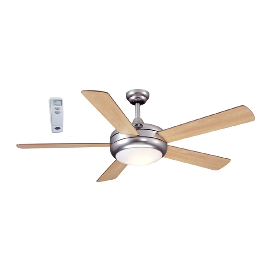
AERO CEILING FAN
MODEL #E-AER52BRZ5LKRCI
Lowes.com/harborbreeze
1
ITEM #0276094
Español p. 20
LISTED
E206035
Advertisement
Table of Contents

Related Manuals for Harbor Breeze AERO CEILING FAN E-AER52BRZ5LKRCI


Summary of Contents for Harbor Breeze AERO CEILING FAN E-AER52BRZ5LKRCI
- Page 1 ITEM #0276094 AERO CEILING FAN MODEL #E-AER52BRZ5LKRCI Español p. 20 Harbor Breeze® is a registered trademark of LF, LLC. All Rights Reserved. LOW MED HIGH Federal regulations require ceiling fans with light kits manufactured or imported after January 1, 2009, to limit total wattage consumed by the light kit to 190W. Therefore, this fan is equipped with a wattage limiting device.
-
Page 2: Table Of Contents
TABLE OF CONTENTS Safety Information .......................2 Package Contents .......................4 Hardware Contents ..........................5 Preparation ..........................5 Initial Installation ........................6 Fan Mounting ........................8 Wiring ..........................11 Final Installation ......................... 1 3 Automated Learning Process/Activating Code ..............14 Operating Instructions......................15 Care and Maintenance ......................17 Troubleshooting........................17 Limited Lifetime Warranty ....................18 Replacement Parts List .....................19 SAFETY INFORMATION READ AND SAVE THESE INSTRUCTIONS... - Page 3 SAFETY INFORMATION WARNING To reduce the risk of fire, electrical shock, or personal injury, mount fan to outlet box marked "ACCEPTABLE FOR FAN SUPPORT OF 35 LBS. (15.9 KG) OR LESS" and use mounting screws provided with the outlet box. Most outlet boxes commonly used for the support of lighting fixtures are not acceptable for fan support and may need to be replaced.
-
Page 4: Package Contents
PACKAGE CONTENTS LOW MED HIGH PART DESCRIPTION QUANTITY PART DESCRIPTION QUANTITY Canopy Mounting Screw Downrod (preassembled) Canopy Pin (preassembled) Mounting Bracket Clip (preassembled) Motor Housing Glass Shade Yoke Cover Star Washer Blade (preassembled) Remote Control Transmitter Remote Control Receiver Battery Motor Screw IMPORTANT REMINDER: You must use the (preassembled) -
Page 5: Hardware Contents
HARDWARE CONTENTS (shown actual size) Blade Fiber Screw Blade E3 Wire Washer Connector Qty. 15 + 1 extra Qty. 15 Qty. 6 + 1 extra + 4 extra PREPARATION Before beginning assembly of product, make sure all parts are present. Compare parts with package contents list and hardware contents list. -
Page 6: Initial Installation
INITIAL INSTALLATION Turn off circuit breakers and wall switch to the fan supply line leads. DANGER: Failure to disconnect power supply prior to installation may result in serious injury or death. Determine mounting method to use. A. Standard mount B. Angle mount IMPORTANT: If using the angle mount, ensure the ceiling angle is not steeper than 19°. - Page 7 INITIAL INSTALLATION 4a. Loosen canopy mounting screws (L) in slotted holes of canopy (B) and remove the other two canopy mounting screws (L) and star washers (P); save canopy mounting screws (L) and star washers (P) for later use. Remove mounting bracket (C) from canopy (B). Secure mounting bracket (C) to outlet box (not included) using screws, spring washers and flat washers provided with the outlet box.
-
Page 8: Fan Mounting
FAN MOUNTING Lift the preassembled yoke plate and the top of motor housing (D) from motor and set aside. Yoke Plate Insert the blade (F) through the slot on the band on the motor housing (D). Align holes in blade (F) with holes inside motor. - Page 9 FAN MOUNTING Remove pin (M) and clip (N) from downrod (A). Partially loosen preassembled set screws in motor housing yoke on top of motor housing (D). *Helpful Hint: Downrod-style mounting is best suited for ceilings 8 ft. high or higher. For taller Screw ceilings you may want to use a longer downrod (not included).
- Page 10 FAN MOUNTNG Depending on the length of downrod you use, you may need to cut the lead wires back to simplify the wiring. If you decide to cut back the lead wires, it is suggested you do so in the following manner: Take the lead wires and make sure you have pulled them all the way through the top of the downrod.
-
Page 11: Wiring
WIRING WARNING: To reduce the risk of fire, electrical shock, or personal injury, wire connectors provided with this fan are designed to accept only one 12-gauge house wire and two lead wires from the fan. If your house wire is larger than 12-gauge or there is more than one house wire to connect to the corresponding fan lead wires, consult an electrician for the proper size wire connectors to use. - Page 12 WIRING Wrap electrical tape (not included) around each individual wire connector (CC) down to the wire. WARNING: Make sure no bare wire or wire strands are visible after making connections. Place green and white connections on opposite side of box from the black and blue (if applicable) connections.
-
Page 13: Final Installation
FINAL INSTALLATION 1. Lift canopy (B) to mounting bracket (C) and align slotted holes in canopy (B) with loosened canopy mounting screws (L) in mounting bracket (C). Twist canopy (B) to lock, then insert the two canopy mounting screws (L) and star washers (P) previously removed (Step 4a, page 7). -
Page 14: Automated Learning Process/Activating Code
AUTOMATED LEARNING PROCESS/ACTIVATING CODE CAUTION: The remote control transmitter (G) can be programmed to multiple receivers or fans. If this is not desired, turn wall switch off to any other programmable receiver or fan. Remove battery cover from back of remote control transmitter (G). -
Page 15: Operating Instructions
AUTOMATED LEARNING PROCESS/ACTIVATING CODE Modifications not approved by the party responsible for compliance could void the user's authority to operate the equipment. *NOTE: This equipment has been tested and found to comply with the limits for a Class B digital device, pursuant to Part 15 of the FCC Rules. - Page 16 OPERATING INSTRUCTIONS 2. Use the fan reverse switch, located on top of the motor housing (D), to optimize the fan for seasonal performance. A ceiling fan will allow you to raise your thermostat setting in summer and lower your thermostat setting in winter without feeling a difference in your comfort.
-
Page 17: Care And Maintenance
CARE AND MAINTENANCE At least twice each year, lower canopy (B) to check downrod (A) assembly, and then tighten all screws on the fan. Clean motor housing (D) with only a soft brush or lint-free cloth to avoid scratching the finish. Clean blades (F) with a lint-free cloth. You may occasionally apply a light coat of furniture polish to wood blades for added protection. -
Page 18: Limited Lifetime Warranty
TROUBLESHOOTING PROBLEM POSSIBLE CAUSE CORRECTIVE ACTION Fan operates but 1. Bulb not installed correctly. 1. Re-install bulb. light fails (if 2. Wires in canopy not wired 2. Check wires in canopy and, applicable). properly. if necessary, re-wire according to instructions on pages 11 and 3. -
Page 19: Replacement Parts List
Canopy Mounting Screw 276094-L 276094-M Clip 276094-N Glass Shade 276094-O Star Washer 276094-P Blade Screw 276094-AA Fiber Blade Washer 276094-BB E3 Wire Connector 276094-CC Printed in China Harbor Breeze® is a registered trademark of LF, LLC. All Rights Reserved. Lowes.com/harborbreeze LI1307...
Need help?
Do you have a question about the AERO CEILING FAN E-AER52BRZ5LKRCI and is the answer not in the manual?
Questions and answers
Aero breeze VKCF-240717-01Model decorative circle is damaged. How can I get another?