Table of Contents
Advertisement
HARBOR BREEZE and logo design are
trademarks or registered trademarks of
LF, LLC. All rights reserved.
ATTACH YOUR RRECEIPT HERE
Serial Number
Questions, problems, missing parts? Before returning to your retailer, call our customer
service department at 888-251-1003, 8 a. m. – 8 p.m., EST, Monday – Sunday. You could
also contact us at partsplus@lowes.com or visit www.lowespartsplus.com.
AS21296
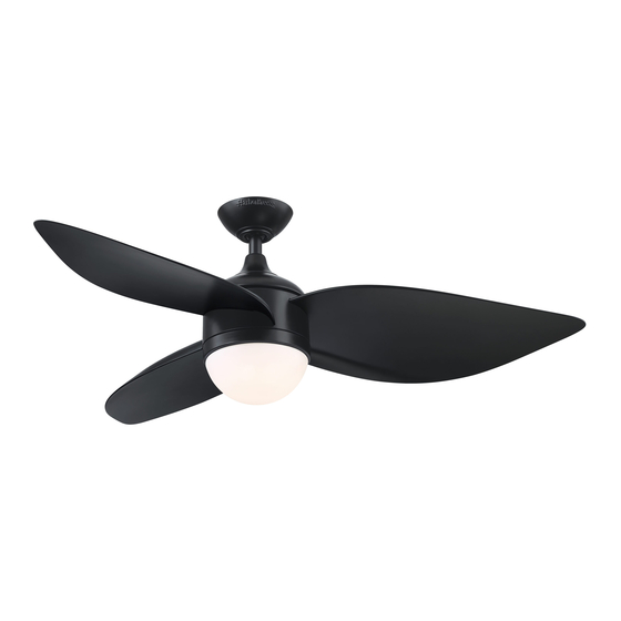
AYRESHIRE CEILING FAN
Purchase Date
1
ITEM # 4067991
MODEL #HTE21091
Español p. 20
Advertisement
Table of Contents

Subscribe to Our Youtube Channel
Related Manuals for Harbor Breeze HTE21091


Summary of Contents for Harbor Breeze HTE21091
- Page 1 ITEM # 4067991 AYRESHIRE CEILING FAN MODEL #HTE21091 Español p. 20 HARBOR BREEZE and logo design are trademarks or registered trademarks of LF, LLC. All rights reserved. ATTACH YOUR RRECEIPT HERE Purchase Date Serial Number Questions, problems, missing parts? Before returning to your retailer, call our customer service department at 888-251-1003, 8 a.
-
Page 2: Table Of Contents
TABLE OF CONTENTS Package Contents....................... Hardware Contents......................Safety Information....................... Preparation ......................... Initial Installation Instructions ....................Standard/Angle-Mounting Instructions................. Wiring Instructions ......................Final Installation Instruction....................Operating Instruction ......................Care and Maintenance ....................... Troubleshooting........................Limited Lifetime Warranty....................FCC Warning........................18 Replacement Part List ...................... -
Page 3: Package Contents
PACKAGE CONTENTS 3h 6h TIMER CR2032 3V PART DESCRIPTION QUANTITY PART DESCRIPTION QUANTITY Clevis Pin [Preassembled on Mounting Bracket Downrod Assembly (B)] Hairpin Clip [Preassembled on Downrod Assembly Downrod Assembly (B)] Canopy Coupling Screw [Preassembled on Coupling (O)] Canopy Cover Coupling [Preassembled on Motor Assembly (F)] Coupling Cover... -
Page 4: Hardware Contents
HARDWARE CONTENTS (not shown actual size) Blade Screw Qty: 9 + 1 extra SAFETY INFORMATION READ AND SAVE THESE INSTRUCTIONS Please read and understand this entire manual before attempting to assemble, operate or install the product. . All electrical connections must comply with local codes, ordinances or the National Electric Code (NEC). Contact your municipal building department to inquire about your local codes, permits and/or inspections. -
Page 5: Preparation
WARNING Risk of fire. Most dwellings built before 1985 have supply wire rated for 140°F. Consult a qualified electrician before installation. To reduce the risk of fire or electric shock, do not use this fan with any solid state fan speed device or variable speed control. -
Page 6: Initial Installation Instructions
INITIAL INSTALLATION INSTRUCTIONS 1. Turn off circuit breakers and wall switch to the fan supply line leads. Turn Off Power Source DANGER: Failure to disconnect power supply prior to installation may result in serious injury or death. 2. Choose the desired mounting method: A. -
Page 7: Standard/Angle-Mounting Instructions
INITIAL INSTALLATION INSTRUCTIONS 4. Loosen the two coupling screws (N) preassembled in the coupling (O), but do not remove them. Remove the hairpin clip (M) and clevis pin (L) from the downrod assembly (B). Retain for later use. Note: Make sure to keep loose hardware separate to avoid confusion during installation. - Page 8 STANDARD/ANGLE-MOUNTING INSTRUCTIONS 3. Cut off excess fixture wires, leaving approximately 6 to 9 inches above the top of the downrod assembly (B). 6 to 9 in. Strip 1/2 inch of insulation from the end of each fixture wire. CAUTION: Ensure all screws are tight before moving to the next step.
-
Page 9: Wiring Instructions
WIRING INSTRUCTIONS WARNING: To avoid possible electrical shock, be sure electricity is turned off at the main fuse box before hanging. WARNING: If you are not sure if the outlet box is grounded, contact a licensed electrician for advice, as it must be grounded for safe operation. WARNING: If house wires are different colors than referred to in the following steps, stop immediately. -
Page 10: Final Installation Instruction
FINAL INSTALLATION INSTRUCTIONS 1. Loosen (but do not remove) the two preassembled mounting bracket screws (P) on mounting bracket (A) that align with the slotted holes on canopy (C). Lift canopy (C) up so slotted holes engage loosened screw heads on mounting bracket (A), then twist canopy (C) clockwise, then tighten all screws securely. - Page 11 FINAL INSTALLATION INSTRUCTIONS 4. Remove one of the mounting screws (Q) on mounting plate of motor assembly (F), then loosen the other two. (remove) Screws (loosen only) 5. Insert the 9-pin connector from the motor assembly through the center hole in the switch housing (H). Attach the switch housing (H) to the mounting plate on the motor assembly by placing the keyhole slots from the switch housing (H) onto the two protruding...
- Page 12 FINAL INSTALLATION INSTRUCTIONS 7. Remove three switch housing screws (R) on the switch housing (H) and keep for later use. (remove) 8. Attach the connector from light kit (I) to the connector from the motor assembly. Align three holes on the light kit (I) and the switch housing (H).
-
Page 13: Operating Instruction
OPERATIING INSTRUCTIONS 1. When the season changes, you may want to change the direction in which the fan spins. In warmer weather, counterclockwise rotation creates a downward airflow, which cools the air. Push the switch LEFT and see a SUN icon. In cooler weather, clockwise rotation creates an upward airflow, which moves hot air from the ceiling. - Page 14 OPERATIING INSTRUCTIONS 4. To make fan operational, install a 3V CR2032 battery (included). Replace the battery cover. NOTE: If not used for long periods of time, remove battery to prevent damage to transmitter. Store the remote control away from excessive heat and humidity. NOTE: Each transmitter of this remote control carries a unique ID code to facilitate communication between paired devices.
-
Page 15: Care And Maintenance
OPERATING INSTRUCTIONS 5. Remote functions: Turn speed up. Turn speed down. Turn fan ON/ OFF. a.) Turn light ON/OFF. b.) Press and hold the button to start circular dimming, the transmitter will beep twice when the light is brightest or darkest. Press this button to switch color temperature when the light is on. -
Page 16: Troubleshooting
TROUBLESHOOTING PROBLEM PROBABLE CAUSE CORRECTIVE ACTION 1. Set screws are loose. 1. Tighten all set screws. 2. Using non-approved speed control. 2. Some fan motors are sensitive to signals from solid- state varible speed controls. DO NOT USE a solid- state variable speed control. -
Page 17: Limited Lifetime Warranty
LIMITED LIFETIME WARRANTY The manufacturer warrants this fan to be free from defects in workmanship and material present at time of shipment from the factory for life (with limitations) from the date of purchase. This warranty applies only to the original purchaser. The manufacturer agrees to correct such defect at no charge or, at our option, replace the ceiling fan with a comparable or superior model. -
Page 18: Fcc Warning
FCC WARNING This device (including remote control and LED module) complies with Part 15 of the FCC Rules. Operation is subject to the following two conditions: (1) This device may not cause harmful interference, and (2) this device must accept any interference received, including interference that may cause undesired operation. -
Page 19: Replacement Part List
REPLACEMENT PART LIST For replacement parts, call our customer service department at 888-251-1003 8 a.m. -8 p.m., EST, Monday – Sunday. You could also contact us at partsplus@lowes.com or visit www.lowespartsplus.com. 3h 6h TIMER CR2032 3V Part Description Part# Mounting Bracket A102-0406084 Downrod Assembly A103-0328401...
Need help?
Do you have a question about the HTE21091 and is the answer not in the manual?
Questions and answers