Table of Contents
Advertisement
Available languages
Available languages
Harbor Breeze® is a registered trademark
of LF, LLC. All Rights Reserved.
Federal regulations require ceiling fans with light kits manufactured or imported after
January 1, 2009, to limit total wattage consumed by the light kit to 190W. Therefore,
this fan is equipped with a wattage limiting device.
ATTACH YOUR RECEIPT HERE
Serial Number
Questions, problems, missing parts? Before returning to your retailer, call or contact our
customer service department at 1-800-527-1292, 8:30 a.m. - 5:00 p.m., CST, Monday - Friday.
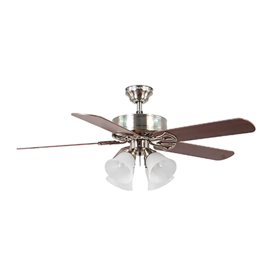
SPRINGFIELD II CEILING FAN
Purchase Date
1
ITEM #0152426
MODEL #E-BDB52ABZC5BC4N
E-BDB52BNK5BC4N
E-BDB52LW5BC4N
E-BDB52MBK5BC4N
Español p. 22
0156738
0158620
0204925
LISTED
E192641
Advertisement
Chapters
Table of Contents
Troubleshooting

Related Manuals for Harbor Breeze E-BDB52ABZC5BC4N


Summary of Contents for Harbor Breeze E-BDB52ABZC5BC4N
- Page 1 ITEM #0152426 0156738 0158620 0204925 Harbor Breeze® is a registered trademark SPRINGFIELD II CEILING FAN of LF, LLC. All Rights Reserved. MODEL #E-BDB52ABZC5BC4N E-BDB52BNK5BC4N E-BDB52LW5BC4N E-BDB52MBK5BC4N Español p. 22 Federal regulations require ceiling fans with light kits manufactured or imported after LISTED January 1, 2009, to limit total wattage consumed by the light kit to 190W.
-
Page 2: Table Of Contents
TABLE OF CONTENTS Safety Information ........………………………………………………...……..2 - 3 Product Overview ...........................4 Package Contents ..……………………………………………………………..….…....5 Hardware Contents .........................6 Preparation ....….…………………..……………………….…………….………………..6 Initial Installation ....….……………..……………………….……….…..…......7 - 8 Downrod Style Fan Mounting ....................8 - 10 Closemount Style Fan Mounting ....................10 - 11 Wiring .........……………………........…………...12 - 13 Final Installation... -
Page 3: Safety Information
SAFETY INFORMATION WARNINGS To reduce the risk of fire, electrical shock, or personal injury, mount fan to outlet box marked "ACCEPTABLE FOR FAN SUPPORT OF 35 LBS (15.9 KG) OR LESS" and use mounting screws provided with the outlet box. Most outlet boxes commonly used for the support of lighting fixtures are not acceptable for fan support and may need to be replaced. -
Page 4: Product Overview
Congratulations on your purchase of this Harbor Breeze® Ceiling Fan! This product has been specifically designed to give you all the performance you’ll ever need. Harbor Breeze® is the perfect fusion of smart innovation and beautiful style. Designed for more than just air movement, our products are built to function flawlessly... -
Page 5: Package Contents
PACKAGE CONTENTS PART DESCRIPTION QUANTITY PART DESCRIPTION QUANTITY Downrod Switch Housing Cap (preassembled) Canopy Lock Washer Mounting Bracket (preassembled) Motor Housing Canopy Mounting Screw Plastic Locking Mechanism (preassembled) Light Kit Fitter Pin (preassembled) Blade Clip (preassembled) Blade Arm Light Kit Fitter Screw Glass Shade (preassembled) Candelabra Base Bulb... -
Page 6: Hardware Contents
HARDWARE CONTENTS (shown actual size) E3 Wire Connector Qty. 4 PREPARATION Before beginning assembly of product, make sure all parts are present. Compare parts with “Package Contents” list and diagrams on the previous page. If any part is missing or damaged, do not attempt to assemble the product. -
Page 7: Initial Installation
INITIAL INSTALLATION Turn off circuit breakers and wall switch to the fan supply line leads. (Fig. 1) DANGER: Failure to disconnect power supply prior to installation may result in serious injury or death. Determine mounting method to use. (Fig. 2) A. -
Page 8: Downrod Style Fan Mounting
INITIAL INSTALLATION Secure mounting bracket (C) to outlet box using screws, spring washers, and flat washers provided with the outlet box. (Fig. 4) *NOTE: It is very important that you use the proper hardware when installing the mounting bracket (C) as this will support the fan. IMPORTANT: If using the angle mount, make sure open end of mounting bracket (C) is installed facing the higher point of the ceiling. - Page 9 DOWNROD STYLE FAN MOUNTING 2. Insert downrod (A) through canopy (B). Thread wires from motor housing (D) through downrod (A). (Fig. 2) Screw Depending on the length of downrod (A) you use, you may need to cut the lead wires back to simplify the wiring.
-
Page 10: Closemount Style Fan Mounting
DOWNROD STYLE FAN MOUNTING If you decided to cut back the lead wires in Step 4, strip 1/2 in. of insulation from end of white wire. Twist stripped ends of each strand of wire within the insulation with pliers (not included). (Fig. -
Page 11: Closemount Style Fan Mounting
CLOSEMOUNT STYLE FAN MOUNTING If neccessary, remove every other screw and lock washer from top of motor housing (D). (If there are only three screws and lock washers in top of motor housing (D), the other three screws and lock washers will be located in one of the hardware packs.) (Fig. -
Page 12: Wiring
WIRING WARNING: To reduce the risk of fire, electrical shock, or personal injury, wire connectors provided with this fan are designed to accept only one 12-gauge house wire and two lead wires from the fan. If your house wire is larger than 12-gauge or there is more than one house wire to connect to the two fan lead wires, consult an electrician for the proper size wire connectors to use. -
Page 13: Wiring
WIRING 1C. FAN AND LIGHT CONTROLLED BY FAN AND LIGHT CONTROLLED BY TWO WALL SWITCHES TWO WALL SWITCHES: If you intend to control the fan and light with separate wall BLACK (WALL SWITCH) switches, connect BLACK wire from fan to BLACK (WALL SWITCH FOR LIGHT) 120 V Power BLACK wire from the independent wall switch... -
Page 14: Final Installation
FINAL INSTALLATION 1. Temporarily lift canopy (B) to mounting bracket (C) to determine which two canopy mounting screws (P) in mounting bracket (C) align with slotted holes in canopy (B) and partially loosen these two canopy mounting screws (P). Remove the other two canopy mounting screws (P). - Page 15 FINAL INSTALLATION Locate motor screws (M) and lock washers (O) that were removed in Step 5 on page 8. Insert two motor screws (M), along with lock washers (O), through one blade arm (H) to attach blade arm (H) to motor housing. Tighten motor screws (M) securely.
- Page 16 FINAL INSTALLATION Align holes in light kit fitter (F) with holes in switch housing. Make sure to align gap on edge of switch housing cap (N) with reverse switch on switch housing for the proper fit. Re-insert the light kit fitter screws (S) that were removed at the beginning of Switch Step 5, Fig.
-
Page 17: Operation Instructions
FINAL INSTALLATION The pull chain extensions (K) supplied in one of the hardware packs or custom pull chain extensions (not included) may be attached to fan and light pull chains. (Fig. 10) NOTE: This fan is remote control adaptable (remote control not included). - Page 18 OPERATION INSTRUCTIONS 3. Use the fan reverse switch, located on the switch housing, to optimize your fan for seasonal performance. (Fig. 3) A ceiling fan will allow you to raise your thermostat setting in Switch summer and lower your thermostat setting in Housing winter without feeling a difference in your comfort.
-
Page 19: Care And Maintenance
CARE AND MAINTENANCE At least twice each year, lower canopy (B) to check downrod (A) assembly, and then tighten all screws on the fan. Clean motor housing (D) with only a soft brush or lint-free cloth to avoid scratching the finish. Clean blades (G) with a lint-free cloth. You may occasionally apply a light coat of furniture polish to wood blades for added protection. -
Page 20: Troubleshooting
TROUBLESHOOTING PROBLEM POSSIBLE CAUSE CORRECTIVE ACTION 3. Wall switch to fan is off. 3. Make sure that wall switch to fan is on. 4. Wires in switch housing not connected 4. Check wires in switch housing properly. and, if necessary, re-wire according to instructions on page 5. -
Page 21: Replacement Parts List
REPLACEMENT PARTS LIST For replacement parts, call our customer service department at 1-800-527-1292, 8:30 a.m. - 5:00 p.m., CST, Monday - Friday. When ordering parts, please have the Model # or Item # of the fan available, which can be found on page 1. PART DESCRIPTION Downrod... - Page 22 Harbor Breeze es una marca registrada VENTILADOR DE de LF, LLC. Todos los derechos reservados. TECHO SPRINGFIELD II MODELO # E-BDB52ABZC5BC4N E-BDBBNK5BC4N E-BDB52LW5BC4N E-BDB52MBK5BC4N Los reglamentos federales requieren que los ventiladores de techo con kit de iluminación fabricados o importados después del 1.° de enero de 2009, tengan un límite LISTED de vataje total consumido por el kit de iluminación de 190 W.
- Page 23 ÍNDICE Información de seguridad .....………………………………………………...……..23 - 24 Descripción general del producto ....................25 Contenido del paquete ..………………………………………………………..….…......26 Aditamentos ..........................27 Preparación ....….…………………..……………………….…………….………………....27 Instalación inicial ....….……………..………………….……….…..…......28 - 29 Estilo de montaje de varilla del ventilador ................29 - 31 Estilo de montaje cerrado del ventilador ................31 - 32 Cableado ........………………........…………....33 - 34...
-
Page 24: Información De Seguridad
INFORMACIÓN DE SEGURIDAD ADVERTENCIAS Para reducir el riesgo de incendios, descargas eléctricas o lesiones personales, monte a una caja de salida marcada como “ACCEPTABLE FOR FAN SUPPORT OF 35 LBS (15.9 KG) OR LESS” (apta para sostener un ventilador de 15,88 kg [35 lb] o menos) y utilice los tornillos de montaje incluidos en la caja de salida. -
Page 25: Descripción General Del Producto
LF, LLC. Todos los derechos reservados. Obtenga calidad de sala de exhibición a un precio ® excepcional con Harbor Breeze , disponible exclusivamente en Lowe's. Decidir cómo desea que luzca y funcione su ventilador de techo es un paso importante antes de la instalación. -
Page 26: Contenido Del Paquete
CONTENIDO DEL PAQUETE PIEZA DESCRIPCIÓN CANTIDAD PIEZA DESCRIPCIÓN CANTIDAD Varilla Tapa de la carcasa del interruptor (preensamblada) Base Arandela de seguridad Abrazadera de montaje (preensamblada) Carcasa del motor Tornillo de montaje de la base Mecanismo de bloqueo de plástico (preensamblado) Soporte del kit de iluminación Pasador (preensamblado) Aspa... -
Page 27: Aditamentos
ADITAMENTOS (se muestran en tamaño real) Conector de cables E3 Cant. 4 PREPARACIÓN Antes de comenzar a ensamblar el producto, asegúrese de tener todas las piezas. Compare las piezas con la lista del “Contenido del paquete” y los diagramas de la página anterior. No intente ensamblar el producto si falta alguna pieza o si estas están dañadas. -
Page 28: Instalación Inicial
INSTALACIÓN INICIAL Interrumpa el suministro de energía del ventilador apagando los interruptores de circuito y el interruptor de pared. (Fig. 1) PELIGRO: Si no interrumpe el suministro de electricidad antes de la instalación, pueden producirse lesiones graves o la muerte. Determine el método de instalación que utilizará. -
Page 29: Estilo De Montaje De Varilla Del Ventilador
INSTALACIÓN INICIAL Asegure la abrazadera de montaje (C) a la caja de salida con los tornillos, las arandelas de resorte y las arandelas planas que incluye la caja de salida. (Fig. 4) *NOTA: Es muy importante que use los aditamentos adecuados para instalar la abrazadera de montaje (C), ya que esta soportará... - Page 30 ESTILO DE MONTAJE DE VARILLA DEL VENTILADOR 2. Introduzca la varilla (A) por la base (B). Pase los conductores desde la carcasa del motor (D) a través de la varilla (A). (Fig. 2) Tornillo fijación Dependiendo del largo de la varilla (A) que utilice, es posible que necesite cortar los cables conductores para simplificar el cableado.
-
Page 31: Estilo De Montaje Cerrado Del Ventilador
ESTILO DE MONTAJE DE VARILLA DEL VENTILADOR Si decidió cortar los cables conductores en el paso 4, pele 12,7 mm del aislamiento del extremo del conductor blanco. Tuerza los extremos pelados de cada filamento de conductor dentro del aislamiento con pinzas (no incluidas). - Page 32 ESTILO DE MONTAJE CERRADO DEL VENTILADOR Si es necesario, retire todos los otros tornillos y las arandelas de seguridad de la parte superior de la carcasa del motor (D). (Si solo hay tres tornillos y arandelas de seguridad en la parte superior de la carcasa del motor (D), los otros tres tornillos y arandelas de seguridad estarán ubicados en uno de los paquetes de aditamentos).
-
Page 33: Cableado
CABLEADO ADVERTENCIA: Para reducir el riesgo de incendios, descargas eléctricas o lesiones personales, los conectores de cables incluidos con este ventilador están diseñados para soportar solo un cable interno de calibre 12 y dos cables conductores del ventilador. Si el cable interno es de un calibre superior a 12 o hay más de un cable interno para conectar a los dos cables conductores del ventilador, pregúntele a un electricista cuál es el... - Page 34 CABLEADO 1C. VENTILADOR Y LUZ CONTROLADOS VENTILADOR Y LUZ CONTROLADOS POR DOS INTERRUPTORES DE PARED POR DOS INTERRUPTORES DE PARED: Si desea controlar el ventilador y la luz con NEGRO (INTERRUPTOR DE PARED) interruptores de pared separados, conecte el NEGRO (INTERRUPTOR DE PARED PARA LA LUZ) Alimentación conductor NEGRO del ventilador al conductor de 120 V...
-
Page 35: Instalación Final
INSTALACIÓN FINAL 1. Levante temporalmente la base (B) hacia la abrazadera de montaje (C) para determinar cuáles son los dos tornillos de montaje de la base (P) en la abrazadera de montaje (C) que se alinean con los orificios ranurados en la base (B) y afloje parcialmente estos dos tornillos de montaje de la base (P). - Page 36 INSTALACIÓN FINAL Localice los tornillos del motor (M) y las arandelas de seguridad (O) que retiró en el paso 5 en la página 29. Inserte dos tornillos del motor (M), junto con arandelas de seguridad (O) a través de un brazo de aspa (H) para fijar el brazo del aspa (H) a la carcasa del motor.
- Page 37 INSTALACIÓN FINAL Alinee los orificios del soporte del kit de iluminación (F) con los orificios de la carcasa del interruptor. Asegúrese de alinear el espacio en el extremo de la tapa de la carcasa del interruptor (N) con el interruptor de reversa de la carcasa del interruptor Carcasa del para que calce correctamente.
-
Page 38: Instrucciones De Funcionamiento
INSTALACIÓN FINAL Las extensiones de cadenas de tiro (K) que se suministran en uno de los paquetes de aditamentos o las extensiones de cadenas de tiro a la medida (no incluidas) se pueden fijar a las cadenas de tiro del ventilador y la luz. (Fig. 10) NOTA: Este ventilador es adaptable para control remoto (el control remoto no se incluye). - Page 39 INSTRUCCIONES DE FUNCIONAMIENTO 3. Utilice el interruptor de reversa del ventilador, ubicado en la carcasa del interruptor, para optimizar el rendimiento de su ventilador según la estación del año. (Fig. 3) Un ventilador de Carcasa techo le permitirá elevar la configuración de su interruptor termostato en verano y disminuirla en invierno, sin sentir una diferencia en su comodidad.
-
Page 40: Cuidado Y Mantenimiento
CUIDADO Y MANTENIMIENTO Al menos dos veces al año, baje la base (B) para revisar el ensamble de la varilla (A) y luego apriete todos los tornillos en el ventilador. Limpie la carcasa del motor (D) solo con un cepillo suave o un paño que no produzca pelusas para evitar rayar el acabado. -
Page 41: Garantía
SOLUCIÓN DE PROBLEMAS PROBLEMA CAUSA POSIBLE ACCIÓN CORRECTIVA 2. Los conductores de la base (B) no 2. Revise los conductores de la base (B) y, están bien conectados. si es necesario, vuelva a conectarlos de acuerdo con las instrucciones de las páginas 33 y 34. -
Page 42: Lista De Piezas De Repuesto
LISTA DE PIEZAS DE REPUESTO Para obtener piezas de repuesto, llame a nuestro Departamento de Servicio al Cliente al 1-800-527-1292, de lunes a viernes de 8:30 a.m. a 5:00 p.m., hora central estándar. Cuando pida piezas, tenga a mano el número de modelo o el número de artículo del ventilador disponibles;...
Need help?
Do you have a question about the E-BDB52ABZC5BC4N and is the answer not in the manual?
Questions and answers
need blades
You can find replacement blades for the Harbor Breeze ceiling fan model E-BDB52ABZC5BC4N using part number 0158620-F.
This answer is automatically generated