Table of Contents
Advertisement
Available languages
Available languages
Harbor Breeze
®
is a registered trademark
of LF, LLC. All Rights Reserved.
ATTACH YOUR RECEIPT HERE
Serial Number ____________
Questions, problems, missing parts? Before returning to your retailer, call our customer
service department at 1-800-643-0067, 8 a.m. - 6 p.m., EST, Monday - Thursday,
8 a.m. - 5 p.m., EST, Friday.
EB13135
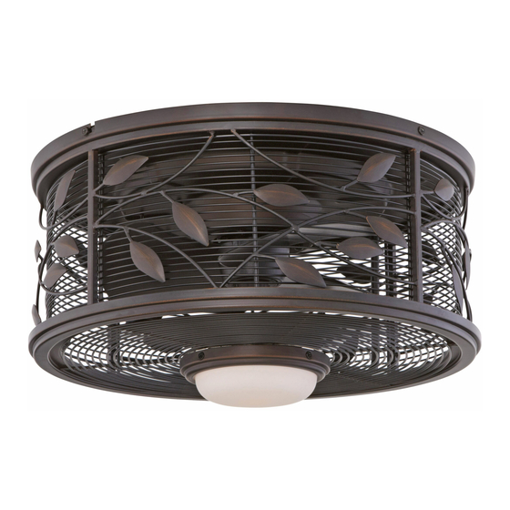
HIVE SERIES CEILING FAN
R
Purchase Date ____________
1
ITEM # 0449504
MODEL # LP8271LAZ
Español p. 16
Lowes.com/harborbreeze
Advertisement
Chapters
Table of Contents

Related Manuals for Harbor Breeze HIVE Series


Summary of Contents for Harbor Breeze HIVE Series
- Page 1 ITEM # 0449504 HIVE SERIES CEILING FAN MODEL # LP8271LAZ Harbor Breeze ® is a registered trademark of LF, LLC. All Rights Reserved. Español p. 16 ATTACH YOUR RECEIPT HERE Serial Number ____________ Purchase Date ____________ Questions, problems, missing parts? Before returning to your retailer, call our customer service department at 1-800-643-0067, 8 a.m.
-
Page 2: Table Of Contents
TABLE OF CONTENTS Package Contents ............. . 3 Hardware Contents . -
Page 3: Package Contents
PACKAGE CONTENTS PART DESCRIPTION QTY. Motor Assembly Glass Steel Cap Bulb Remote Receiver (Preassembled to Motor Assembly (A)) Ceiling Bracket (Preassembled to Motor Assembly (A)) Battery Lowes.com/harborbreeze... -
Page 4: Hardware Contents
HARDWARE CONTENTS (not shown actual size) Wire Ceiling Switch Housing Screw Connector Bracket Screw (Preassembled to (Preassembled to Motor Assembly (A)) Qty.4 Motor Assembly (A)) Qty. 4 Qty. 4 SAFETY INFORMATION Please read and understand this entire manual before attempting to assemble, operate, or install the product. -
Page 5: Preparation
SAFETY INFORMATION WARNING: Do not install or use the fan if any part is damaged or missing. WARNING: To reduce the risk of fi re, electrical shock, or personal injury, wire connectors provided with this fan are designed to accept only one 12-gauge house wire and two lead wires from the fan. -
Page 6: Assembly Instructions
INITIAL ASSEMBLY INSTRUCTIONS 1. Turn off the electricity at the main fuse box before assembly. DANGER: Failure to disconnect the power supply prior to installation may result in serious injury or death. 2. Separate the ceiling bracket (G) from the motor assembly (A) by loosening the two ceiling bracket screws (BB) in the slotted holes, then removing the two remaining ceiling bracket screws (BB) in the... - Page 7 INITIAL ASSEMBLY INSTRUCTIONS 4. Securely attach the ceiling bracket (G) to the outlet box with screws and washers supplied with the outlet box. 5. Loop the preassembled ceiling support cable from the motor assembly (A) over the hook on the ceiling bracket (G).
-
Page 8: Remote Control Instructions
REMOTE CONTROL INSTRUCTIONS 1. To set the transmitter code on the remote (E), remove the battery cover. With a small screwdriver or a ballpoint pen (not included), slide the code switches up or down to a confi guration of your choice. Note: The factory setting is all up;... -
Page 9: Wiring Instructions
WIRING INSTRUCTIONS Note: If you are not sure if the outlet box is grounded, contact a licensed electrician for advice, as it must be grounded for safe operation. 1. Connect the green grounding lead from the wire tray and the green grounding lead from the ceiling bracket (G) to the supply grounding conductor (this may be a bare wire or wire with green colored insulation). -
Page 10: Final Assembly Installation
FINAL ASSEMBLY INSTRUCTIONS 1. Hold the motor assembly (A) and release it from the hook on the ceiling bracket (G). The motor assembly (A) has two mating slots and two mating holes. Position both slots on the motor assembly (A) directly under and in line with the two ceiling bracket screws (BB) in the ceiling bracket (G). - Page 11 FINAL ASSEMBLY INSTRUCTIONS 3. If you wish to use the light kit portion of the motor assembly (A), install the bulb (D) and proceed to step 4. If you do not wish to use the light kit, skip to step 5 directly.
-
Page 12: Operating Instructions
OPERATING INSTRUCTIONS 1. Restore electrical power to the outlet box by turning the electricity on at the main fuse box. 2. Install the 12-volt battery (H) into the remote (E). Press any key on the remote (E) to make sure the blue light is on. -
Page 13: Care And Maintenance
OPERATING INSTRUCTIONS (CONTINUED) 3. Control the fan and light: Low Speed Medium Speed High Speed Turn the fan off. Press this button quickly to turn the lights on or off. To dim the lights, press and hold this button. Release the button when the light is at the desired level. -
Page 14: Troubleshooting
TROUBLESHOOTING PROBLEM POSSIBLE CAUSE CORRECTIVE ACTION The fan will not start. 1. The fuse or circuit breaker is 1. Check the main and branch circuit blown. fuses or circuit breakers. 2. There are loose power line 2. Check the line wire connections to connections to the fan. -
Page 15: Replacement Parts List
Monday - Thursday and 8 a.m. - 5 p.m., EST, Friday. PART DESCRIPTION PART # Motor Assembly AMA8271LAZ Glass AP827115LAZ Steel Cap P827116LAZ Bulb PPE11B75 Remote TR350 Receiver Unit RECAN67 Wire Connector HDWWNUTS4 Printed in China Harbor Breeze ® is a registered trademark of LF, LLC. All Rights Reserved. Lowes.com/harborbreeze... - Page 16 ARTÍCULO # 0449504 VENTILADOR DE TECHO DE LA SERIE HIVE MODELO # LP8271LAZ Harbor Breeze ® es una marca registrada de LF, LLC. Todos los derechos reservados. ADJUNTE SU RECIBO AQUÍ Número de serie ____________ Fecha de compra ____________ ¿Preguntas, problemas, piezas faltantes? Antes de volver a la tienda, llame a nuestro Departamento de Servicio al Cliente al 1-800-643-0067, de lunes a jueves de 8 a.m.
- Page 17 ÍNDICE Contenido del paquete ............18 Aditamentos .
-
Page 18: Contenido Del Paquete
CONTENIDO DEL PAQUETE PIEZA DESCRIPCIÓN CANT. Ensamble del motor Vidrio Tapa de acero Bombilla Control remoto Receptor (Preensamblado en el ensamble del motor (A)) Abrazadera para techo (preensamblada en el ensamble del motor (A)) Batería Lowes.com/harborbreeze... -
Page 19: Aditamentos
ADITAMENTOS (no se muestran en tamaño real) Conector Tornillo de la Tornillo de la carcasa de cables abrazadera para techo del interruptor (preensamblado en el (preensamblado en el Cant. 4 ensamble del motor (A)) ensamble del motor (A)) Cant. 4 Cant. -
Page 20: Preparación
INFORMACIÓN DE SEGURIDAD ADVERTENCIA: No instale ni use el ventilador si falta alguna pieza o si estas están dañadas. ADVERTENCIA: Para reducir el riesgo de incendios, descargas eléctricas o lesiones personales, los conectores de cables proporcionados con este ventilador están diseñados para soportar solo un cable de la casa de calibre 12 y dos cables conductores del ventilador. -
Page 21: Instrucciones De Ensamblaje
INSTRUCCIONES DE ENSAMBLAJE INICIALES 1. Desconecte la electricidad en la caja de fusibles principal antes de ensamblar. PELIGRO: Si no interrumpe el suministro de electricidad antes de la instalación, pueden producirse lesiones graves o la muerte. Separe la abrazadera para techo (G) del ensamble del motor (A), afl... - Page 22 INSTRUCCIONES DE ENSAMBLAJE INICIALES 4. Fije bien la abrazadera para techo (G) a la caja de salida con los tornillos y las arandelas provistas con la caja de salida. 5. Enganche el cable de soporte para techo preensamblado desde el ensamble del motor (A) sobre el gancho en la abrazadera para techo (G).
-
Page 23: Instrucciones Del Control Remoto
INSTRUCCIONES DEL CONTROL REMOTO 1. Para confi gurar el código del transmisor en el control remoto (E), retire la cubierta de la batería. Con un pequeño destornillador o un lápiz de punta redonda (no se incluye), deslice los interruptores de código hacia arriba o hacia abajo a la confi... -
Page 24: Instrucciones De Cableado
INSTRUCCIONES DE CABLEADO Nota: Si no está seguro de si la caja de salida tiene puesta a tierra, solicite ayuda a un electricista certifi cado, ya que debe tener puesta a tierra para un funcionamiento seguro. 1. Conecte el conductor verde con puesta a tierra de la bandeja de conductores y el conductor verde con puesta a tierra de la abrazadera para techo (G) al conductor de suministro con puesta... -
Page 25: Instrucciones De Ensamblaje Finales
INSTRUCCIONES DE ENSAMBLAJE FINALES 1. Sostenga el ensamble del motor (A) y libérelo del gancho en la abrazadera para techo (G). El ensamble del motor (A) tiene dos ranuras y dos orifi cios de acoplamiento. Coloque ambas ranuras del ensamble del motor (A) directamente debajo y alineadas con los dos tornillos de la abrazadera para techo (BB) en la abrazadera para techo (G). - Page 26 INSTRUCCIONES DE ENSAMBLAJE FINALES 3. Si desea usar la sección del kit de iluminación del ensamble del motor (A), instale la bombilla (D) y continúe con el paso 4. Si no desea utilizar el kit de iluminación, pase directamente al paso 5. PRECAUCIÓN: La bombilla está...
-
Page 27: Instrucciones De Funcionamiento
INSTRUCCIONES DE FUNCIONAMIENTO 1. Restablezca la alimentación eléctrica en la caja de salida volviendo a conectar la electricidad de la caja de fusibles principal. 2. Instale la batería de 12 voltios (H) en el control remoto (E). Presione cualquier tecla en el control remoto (E) para asegurarse de que la luz azul se encienda. -
Page 28: Cuidado Y Mantenimiento
INSTRUCCIONES DE FUNCIONAMIENTO (CONTINUACIÓN) 3. Controle el ventilador y la luz: Velocidad baja Velocidad media Velocidad alta Apague el ventilador. Presione rápidamente este botón para encender o apagar las luces. Mantenga presionado este botón para regular la intensidad de las luces. Cuando la intensidad de la luz alcance el nivel deseado, suelte el botón. -
Page 29: Solución De Problemas
SOLUCIÓN DE PROBLEMAS PROBLEMA CAUSA POSIBLE ACCIÓN CORRECTIVA El ventilador 1. El fusible o el interruptor de 1. Revise los fusibles del circuito de no arranca. circuito están fundidos. derivación y del circuito principal o los interruptores de circuito. 2. Revise las conexiones de los cables 2. -
Page 30: Lista De Piezas De Repuesto
Ensamble del motor AMA8271LAZ Vidrio AP827115LAZ Tapa de acero P827116LAZ Bombilla PPE11B75 Control remoto TR350 Unidad receptora RECAN67 Conector de cables HDWWNUTS4 Impreso en China Harbor Breeze ® es una marca registrada de LF, LLC. Todos los derechos reservados. Lowes.com/harborbreeze...
Need help?
Do you have a question about the HIVE Series and is the answer not in the manual?
Questions and answers