
Related Manuals for Extreme Networks 4220 Series


Summary of Contents for Extreme Networks 4220 Series
- Page 1 4220 Series Cloud Managed Switches Hardware Installation Guide 9038082-00 Rev. AA April 2024...
- Page 2 Extreme Networks, Inc. reserves the right to make changes in specifications and other information contained in this document and its website without prior notice. The reader should in all cases consult representatives of Extreme Networks to determine whether any such changes have been made.
-
Page 3: Table Of Contents
Recommendations for Configuring Stacks....................... 32 Combine Switches from Different Series......................33 Select Stacking Cables............................... 33 Using the Extreme Stacking Tool..........................33 Set up the Physical Stack................................34 Connect the Switches to Form the Stack Ring....................35 4220 Series Cloud Managed Switches Hardware Installation Guide... - Page 4 Activate and Verify the Switch....................68 Connect to a Management Console..........................68 Log in for the First Time on Switch Engine......................... 68 Manual Setup.................................... 69 Configure the Switch's IP Address for the Management VLAN..............70 4220 Series Cloud Managed Switches Hardware Installation Guide...
- Page 5 Power Cord Requirements for AC-Powered Switches and AC Power Supplies......90 Select Power Supply Cords................................ 91 Install Power Supply Units and Connect Power....................... 91 Battery Notice..................................... 92 Battery Warning - Taiwan................................93 Regulatory Information......................94 CE statement.......................................94 EMC Warnings....................................95 4220 Series Cloud Managed Switches Hardware Installation Guide...
- Page 6 BSMI statement (Taiwan)................................95 Canadian requirements................................95 Australia (RCM)....................................95 Federal Communications Commission (FCC) Notice..................95 Germany statement..................................96 KCC statement (Republic of Korea)........................... 96 Japan (VCCI Class A)..................................96 Japan power cord ................................... 97 Index..............................98 4220 Series Cloud Managed Switches Hardware Installation Guide...
-
Page 7: Preface
When a feature, function, or operation pertains to a specific hardware product, the product name is used. When features, functions, and operations are the same across an entire product family, such as Extreme Networks switches or SLX routers, the product is the switch or the router . -
Page 8: Documentation And Training
When a backslash separates two lines of a command input, enter the entire command at the prompt without the backslash. Documentation and Training Find Extreme Networks product information at the following locations: 4220 Series Cloud Managed Switches Hardware Installation Guide... -
Page 9: Open Source Declarations
Some software files have been licensed under certain open source licenses. Information is available on the Open Source Declaration page. Training Extreme Networks offers product training courses, both online and in person, as well as specialized certifications. For details, visit the Extreme Networks Training page. Help and Support... -
Page 10: Subscribe To Product Announcements
You can modify your product selections or unsubscribe at any time. Send Feedback The User Enablement team at Extreme Networks has made every effort to ensure that this document is accurate, complete, and easy to use. We strive to improve our documentation to help you in your work, so we want to hear from you. -
Page 11: 4220 Cloud Managed Switch Overview
There is one Micro-B USB console port located on the front panel. If the Micro-B USB console port is connected, it is selected over the RJ45 serial console port. The Micro-B USB console port disconnects when the switch is rebooted. You can re-connect the 4220 Series Cloud Managed Switches Hardware Installation Guide... -
Page 12: Cooling
The internal fans are responsible for cooling the internal power supply. Power Supplies Each 4220 Series has a fixed internal AC power supply that provides enough power for the basic power needs of the switch. For switch models that support PoE, the internal power supply also provides a POE power budget beyond the basic switch needs. -
Page 13: Operating Temperatures
Fans function normally if the temperature is between 35°C (95°F) and 50°C (122°F). Feature Licensing A base license for the 4220 Series is the only license supported in Switch Engine. For Feature License Requirements additional Switch Engine licensing information see the for your version of the Switch Engine software. -
Page 14: 4220-12P-4X Switch Features
8 = USB Micro-B console port 9 = Serial console port (RJ-45) Figure 3: 4220-12P-4X Front View The rear panel of the switch includes: 1 = Grounding lug 2 = Power supply power cord input 4220 Series Cloud Managed Switches Hardware Installation Guide... -
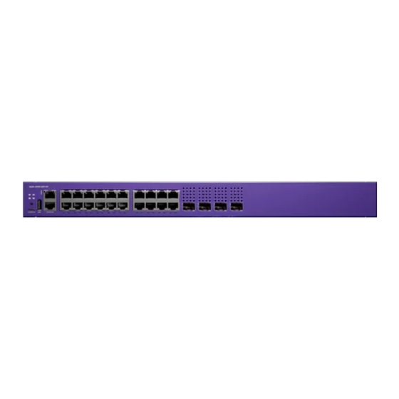
Page 15: 4220-24P-4X Switch Features
1 = Grounding lug 2 = Power supply power cord input 3 = Redundant power supply slot Figure 6: 4220-24P-4X Rear View 4220-24T-4X Switch Features The front panel of the 4220-24T-4X switch includes: 4220 Series Cloud Managed Switches Hardware Installation Guide... -
Page 16: 4220-48P-4X Switch Features
5 = 48 x 10/100/1000Base-T 802.3at (30W) PoE ports 7 = 4 x 1/10Gb SFP+ uplink/stacking ports 8 = USB Micro-B console port 9 = Serial console port (RJ-45) Figure 9: 4220-48P-4X Front View 4220 Series Cloud Managed Switches Hardware Installation Guide... -
Page 17: 4220-48T-4X Switch Features
1 = Grounding lug 2 = Power supply power cord input 3 = Redundant power supply slot Figure 12: 4220-48T-4X Rear View 4220-4MW-20P-4X Switch Features The front panel of the 4220-4MW-20P-4X switch includes: 4220 Series Cloud Managed Switches Hardware Installation Guide... -
Page 18: 4220-4Mw-8P-4X Switch Features
5 = 8 x 10/100/1000Base-T 802.3at (30W) PoE ports 6 = 4 x 1G/2.5G/5GBaseT 802.3bt (90W) PoE ports 7 = 4 x 1/10Gb SFP+ uplink/stacking ports 8 = USB Micro-B console port 9 = Serial console port (RJ-45) 4220 Series Cloud Managed Switches Hardware Installation Guide... -
Page 19: 4220-8Mw-40P-4X Switch Features
7 = 4 x 1/10Gb SFP+ uplink/stacking ports 8 = USB Micro-B console port 9 = Serial console port (RJ-45) Figure 17: 4220-8MW-40P-4X Front View The rear panel of the switch includes: 4220 Series Cloud Managed Switches Hardware Installation Guide... -
Page 20: 4220-8X Switch Features
9 = Serial console port (RJ-45) Figure 19: 4220-8X Front View The rear panel of the switch includes: 1 = Grounding lug 2 = Power supply power cord input Figure 20: 4220-8X Rear View 4220 Series Cloud Managed Switches Hardware Installation Guide... -
Page 21: Redundant Power Supplies For Use With Your Switch
Redundant Power Supplies for Use with Your Switch The 4220 Series switch contains a fixed internal AC power supply that supplies the power needed for most switch operations. Switch models 4220-4MW-20P-4X and 4220-8MW-40P-4X provide the option to add an external redundant power supply (RPS) for power redundancy and a higher PoE budget. -
Page 22: Build Stacks
SummitStack cables. All connections between stack ports must be directly between switches. A stacking connection cannot pass through a third device, for example a Virtual Port Extender or an LRM/MACsec Adapter. 4220 Series Cloud Managed Switches Hardware Installation Guide... -
Page 23: Build Basic Stacks
Note 4220 Series does not support alternate stacking. When planning and building your stack, be sure to follow port compatibility and cabling recommendations as described in this chapter. 4220 Series Cloud Managed Switches Hardware Installation Guide... -
Page 24: Summitstack Topologies
“primary-capable,” meaning they can become a stack primary in case the initial backup switch fails. Note 4220 Series switches can only be stacked with themselves using Native V40 stacking. When easy setup compares two switches that have the same capability, the lower slot number takes precedence. - Page 25 The result forms a physical ring connection. This topology is highly recommended for normal operation. Figure 23 represents a maximal ring topology of eight active nodes. 4220 Series Cloud Managed Switches Hardware Installation Guide...
- Page 26 Connect your stack nodes in a ring topology, not a daisy-chain topology, for normal operation. Figure 25, the nodes delineated as the active topology are operating in a daisy-chain configuration, even though there is physically a ring connection in the stack. 4220 Series Cloud Managed Switches Hardware Installation Guide...
-
Page 27: Summitstack Terms
Table 4: List of Stacking Terms Term Description Stackable switch An Extreme Networks switch that provides two stacking ports and can participate in a stack. Stacking port A physical interface of a stackable switch that is used to allow the connection of a stacking link. Stacking ports are point-to- point links that are dedicated for the purpose of forming a stack. - Page 28 Thus, the active topology is a set of physically contiguous active nodes within a stack topology. 4220 Series Cloud Managed Switches Hardware Installation Guide...
- Page 29 VLAN or trunk group. They can be used for Layer 2 and 3 forwarding of user data traffic, for mirroring, or other features you can configure. Data ports are different from stacking ports. 4220 Series Cloud Managed Switches Hardware Installation Guide...
- Page 30 The choice to run Easy Setup is offered when you run the enable stacking {node-address node-address} command and the essential stacking parameters are unconfigured or inconsistent. It can also be invoked directly by running the configure stacking easy-setup command. 4220 Series Cloud Managed Switches Hardware Installation Guide...
-
Page 31: Plan To Create Your Stack
Use stacking cables to interconnect the stack nodes into a ring topology (see Ring Topology: Recommended for Stacking on page 25). Include only the nodes that you expect to be active in the stack. 4220 Series Cloud Managed Switches Hardware Installation Guide... -
Page 32: Recommendations For Configuring Stacks
. • If EAPS, Spanning Tree, or any Layer 2 redundancy protocol is not running on the network, make sure that your network connections do not form a network loop. 4220 Series Cloud Managed Switches Hardware Installation Guide... -
Page 33: Combine Switches From Different Series
4220 Series switches can only stack with themselves using Native V40 stacking. Select Stacking Cables Stacking connections using the native stacking ports require stacking cables that are specific to the type of stacking port. These cables are available from Extreme Networks in lengths from 0.5 meter to 100 meters. Note... -
Page 34: Set Up The Physical Stack
1. Connect the switches that will form the stack. Connect the Switches to Form the Stack Ring on page 35. 2. Connect the switches to your management network. Connect Your Stack to the Management Network on page 37. 4220 Series Cloud Managed Switches Hardware Installation Guide... -
Page 35: Connect The Switches To Form The Stack Ring
4-node stack using SummitStack 40G cables to connect switches with integrated SummitStack ports. Slot 1 Slot 2 Slot 3 Slot 4 Figure 27: SummitStack Cable Connections Using Four Switches with Integrated SummitStack Ports 4220 Series Cloud Managed Switches Hardware Installation Guide... - Page 36 Stack Port 1 Slot 3 Stack Port 2 Slot 4 Stack Port 1 Slot 4 Stack Port 2 Slot 5 Stack Port 1 Slot 5 Stack Port 2 Slot 6 Stack Port 1 4220 Series Cloud Managed Switches Hardware Installation Guide...
-
Page 37: Connect Your Stack To The Management Network
Connect the Switches to Form the Stack Ring on page 35, and if you use the Easy Setup configuration procedure, only slots 1 and 2 can become the primary node. However, you can connect all switch management 4220 Series Cloud Managed Switches Hardware Installation Guide... - Page 38 Ethernet management port. Switch Engine User's Guide for your version of Switch Engine for instructions to See the perform the software configuration for your stack. 4220 Series Cloud Managed Switches Hardware Installation Guide...
-
Page 39: Site Preparation
The physical installation site must meet the following requirements for a safe and successful installation: • Building and electrical code requirements • Environmental, safety, and thermal requirements for the equipment you plan to install 4220 Series Cloud Managed Switches Hardware Installation Guide... -
Page 40: Operating Environment Requirements
After examining your physical site and verifying that all environment requirements are met, evaluate and compare your existing cable plant with the requirements of the Extreme Networks equipment to determine if you need to install new cables. 3. Meeting power requirements. -
Page 41: Set Up The Wiring Closet
Make sure that your system is easily accessible for installation and service. See Rack Specifications and Recommendations on page 43 for more information. • Use appropriate AC or DC power, power distribution, and grounding for your specific installation. 4220 Series Cloud Managed Switches Hardware Installation Guide... -
Page 42: Control The Temperature
Consult an electrical contractor for commercial building and wiring specifications. Control the Temperature Extreme Networks equipment generates a significant amount of heat. It is essential that you provide a temperature-controlled environment for both performance and safety. Install the equipment only in a temperature- and humidity-controlled indoor area that is free of airborne materials that can conduct electricity. -
Page 43: Control The Humidity Level
Site Preparation Control the Humidity Level Safeguards are built into all Extreme Networks switches and power supply units to minimize the risk of fire. Table 10: Thermal Shutdown and Restart Behavior Switch Model(s) Behavior All models When internal system temperatures exceed the thermal shutdown temperature limit (typically about 20°C higher than normal system... -
Page 44: Mechanical Recommendations For The Rack
Because building codes vary worldwide, consult an electrical contractor to ensure proper equipment grounding for your specific installation. Provide Adequate Space for the Rack Provide enough space in front of and behind the switch so that you can service it easily. 4220 Series Cloud Managed Switches Hardware Installation Guide... -
Page 45: Secure The Rack
(61 cm) of space behind the mounted equipment. Extra room on each side is optional. Warning Extreme Networks switches do not have a switch for turning power to the unit on and off. For systems using an AC power supply, power to the switch is disconnected by removing the wall plug from the electrical outlet. -
Page 46: Label Cables And Keep Accurate Records
• Assign a unique identification number to each equipment rack. • Identify all wiring closets by labeling the front panel of your Extreme Networks equipment and other hardware. • Keep accurate and current cable identification records. - Page 47 Fiber optic cable must be handled carefully during installation. Every cable has a minimum bend radius, and fibers will be damaged if the cables are bent too sharply. It is also important not to stretch the cable during installation. Ensure 4220 Series Cloud Managed Switches Hardware Installation Guide...
-
Page 48: Use Rj45 Connector Jackets
Connectors that are not properly aligned with the port. • Crowded cable installation, which can cause connectors to pop out of the port. Figure 33 shows examples of recommended and non-recommended connector jacket types. 4220 Series Cloud Managed Switches Hardware Installation Guide... -
Page 49: Prevent Radio Frequency Interference (Rfi)
When connecting PoE devices to a PoE switch, all connections between the PoE device and the switch must remain within the same building and use a low-voltage power distribution system per either IEEE 802.3at., IEEE 802.3bt., or IEEE 802.3af. 4220 Series Cloud Managed Switches Hardware Installation Guide... -
Page 50: Power Supply Requirements
For detailed power specifications for your equipment, see "Technical Specifications." Power Cord Requirements Most Extreme Networks switches do not ship with power cords. See Select Power Supply Cords on page 91 for information on selecting and purchasing the correct AC power cords for use with specific Extreme Networks equipment. - Page 51 UPS transition time is sometimes called UPS transition times vary between UPS models and implementations, but shorter transition times are preferred. For Extreme Networks stacking products, a UPS transition time of 20 milliseconds or less ensures optimum performance and minimizes service interruptions.
-
Page 52: Follow Applicable Industry Standards
• ANSI/TIA/EIA-568-A—the six subsystems of a structured cabling system • ANSI/TIA/EIA-569-A—design considerations • ANSI/TIA/EIA-606—cabling system administration • ANSI/TIA/EIA-607—commercial building grounding and bonding requirements You can access these standards at: www.ansi.org or www.tiaonline.org. 4220 Series Cloud Managed Switches Hardware Installation Guide... -
Page 53: Install The Switch
Turn on the Switch on page 67 Connect Network Interface Cables on page 67 Before you attempt to install or remove an Extreme Networks switch, read the precautions in Safety Considerations for Installation on page 53. Extreme Networks switches fit into standard 19-inch equipment racks. -
Page 54: What You Will Need For The Installation
39, and ensure that you have the appropriate people and tools on hand. Installing Extreme Networks switches is easiest when there are two people to maneuver the switch and attach mounting hardware. Provide enough space in front of and behind the switch so that you can service it easily. -
Page 55: Mount Options
You can mount or install the device in the following ways: • All 4220 Series support mounting as a standalone unit on a flat surface, such as a table top. Use the rubber feet included with the device to secure the device on the surface. -
Page 56: Install The Device In A Rack
Install the Switch Install the Device in a Rack The 4220 Series can be installed in a four-post rack, using just the two front posts or two back posts. This procedure uses a two-post mounting kit, which accommodates rack posts 3 inches or 6 inches wide. - Page 57 Install the Device in a Rack Figure 35: Flush-Mount: Attaching mounting ears to models 4220-8X, 4220-4MW-8P-4X, 4220-12P-4X, and 4220-12T-4X Figure 36: Flush-Mount: Attaching mounting ears to models 4220-4MW-20P-4X, 4220-8MW-40P-4X, 4220-48P-4X, 4220-48T-4X, 4220-24P-4X, and 4220-24T-4X 4220 Series Cloud Managed Switches Hardware Installation Guide...
- Page 58 3. Fasten the switch securely to the rack rails using four customer-supplied rack screws. Ensure that the threaded length of the screws is within 4 to 5 cm. The following figures illustrate how to attach the switch to the rack for two common mounting options. 4220 Series Cloud Managed Switches Hardware Installation Guide...
- Page 59 Figure 39: Flush-Mount: Mounting in a Two- or Four-Post Rack for models 4220-8X, 4220-4MW-8P-4X, 4220-12P-4X, and 4220-12T-4X Figure 40: Flush-Mount: Mounting in a Two- or Four-Post Rack for models 4220-4MW-20P-4X, 4220-8MW-40P-4X, 4220-48P-4X, 4220-48T-4X, 4220-24P-4X, and 4220-24T-4X 4220 Series Cloud Managed Switches Hardware Installation Guide...
-
Page 60: Mount The Device On A Wall
Be sure to position the marks so that the switch is level when it is mounted. 2. Drill the holes and attach the brackets using four wood screws and four anchors that are included in the accessory kit, which can be ordered separately. 4220 Series Cloud Managed Switches Hardware Installation Guide... -
Page 61: Mount The Device Under A Table
Models 4220-12P-4X, 4220-12T-4X, and 4220-4MW-8P-4X support silent mode operation at temperatures up to 35°C (95°F). Silent mode requires 1 RU of free space above the switch. Fans function normally if the temperature is between 35°C (95°F) and 50°C (122°F). 4220 Series Cloud Managed Switches Hardware Installation Guide... -
Page 62: Install An External Redundant Power Supply
2. Apply the pads to the underside of the RPS by placing a pad at each corner, ensuring that all corners are aligned. shows the locations for attaching the rubber mounting feet on the switch. 4220 Series Cloud Managed Switches Hardware Installation Guide... -
Page 63: Install The Rps In A Rack
1. Attach a mounting bracket to each side of the RPS, using the screws provided. Align each mounting bracket so that the flange (ear) faces the front of the RPS to flush-mount, or faces the rear of the RPS to mid-mount. 4220 Series Cloud Managed Switches Hardware Installation Guide... - Page 64 2. With the mounting brackets attached, position the RPS between the vertical rack rails of the 19-inch rack. 3. Fasten the RPS securely to the rack rails using four customer-supplied rack screws. 4220 Series Cloud Managed Switches Hardware Installation Guide...
-
Page 65: Connect The Rps Cable And The Ac Power Cord
Connections must be made in a specific order when attaching an RPS to a powered system. The supplied one meter RPS cable (part no. RPS-CBL-1M) is required for use with the RPS-550W and RPS-950W external redundant power supplies. 4220 Series Cloud Managed Switches Hardware Installation Guide... -
Page 66: Install Optional Components
For a list of the optical components supported with ExtremeSwitching devices, see the Extreme Optics website. Pluggable Transceiver Modules Extreme Networks offers several optical transceiver modules for transmitting and receiving data over optical fiber rather than through electrical wires. 4220 Series Cloud Managed Switches Hardware Installation Guide... -
Page 67: Optical Cables
An AC power cord is not included with the AC power supply. You can purchase AC power cords for use in the US and Canada from Extreme Networks or from your local supplier. The cord must meet the requirements listed in... -
Page 68: Activate And Verify The Switch
Parity: None Log in for the First Time on Switch Engine The 4220 Series is designed for easy-to-use cloud management. 4220 Series switches can be managed by either of the native cloud management options ExtremeCloud™ IQ or ExtremeCloud™ IQ Site Engine, avoiding the need for complex on-switch provisioning through a direct console interface. -
Page 69: Manual Setup
2. At the management console, press [Enter] one or more times until you see the login prompt. 3. At the login prompt, log in using the default user name admin. For example: 4220 Series Cloud Managed Switches Hardware Installation Guide... -
Page 70: Configure The Switch's Ip Address For The Management Vlan
Mon 04 Mar 2024 04:42:03 PM UTC BootROM : Default 3.5.0.10 Alternate 3.5.0.10 Diagnostics : 0.0.3.2 Certified Version : EXOS Linux 5.10.177, Extreme Networks FIPS Object Module 2.0.16a Build Tools Version : exos-arm64-sdk-3.1.19.1.0 Note Software upgrade is required. Configure the switch's IP address for the management virtual LAN (VLAN) by following... - Page 71 2. Enter save to save your configuration changes so that they will be in effect after the next system reboot. Note For more information about saving configuration changes, see the . The configuration is saved to the configuration database of the switch. 4220 Series Cloud Managed Switches Hardware Installation Guide...
-
Page 72: Remove And Replace Components
Connections must be removed in a specific order when detaching an RPS from a powered system. To disconnect the RPS: 1. Disconnect the AC power cord from the AC input power connector on the rear of the RPS before disconnecting the RPS cable. 4220 Series Cloud Managed Switches Hardware Installation Guide... - Page 73 Figure 52: RPS cable and AC Power Cord Connection The AC power LED on the rear of the RPS turns off to indicate that the power to the RPS has been disconnected. 4220 Series Cloud Managed Switches Hardware Installation Guide...
-
Page 74: Monitor The Switch
System status LEDs are located on the front of the switch. The following figure shows the status LEDs for 4220 Series switches: Figure 53: 4220 Series Mode and System Status LEDs Port LEDs can display in three different modes: SYS (the default mode), SPD (speed) and STK (stacking). -
Page 75: Power Led
The power LED can indicate the status of both the internal power supply and a connected external redundant power supply (RPS), for models that support connecting an RPS. The power LED first indicates the status of the internal power supply for one 4220 Series Cloud Managed Switches Hardware Installation Guide... -
Page 76: Port Leds In Default (Sys) Mode
Link is active and transmitting packets; port is powered. Slow Blinking Amber No link, or disabled port; port is powered. Alternating Amber and Port has a power fault. Green Port is not powered, has no link, or is disabled. 4220 Series Cloud Managed Switches Hardware Installation Guide... -
Page 77: Port Leds In Spd Mode
LEDs. Right-side LED State Link Solid Green Link up No link up or port disabled. Left-side LED State Blinking Green Packet transmitting or receiving. No packet transmitting or receiving. 4220 Series Cloud Managed Switches Hardware Installation Guide... -
Page 78: External Redundant Power Supply Leds
RPS is out of RPS. specification. 2. Check AC power at the power outlet. 3. Swap power cord for a known good one. If the problem persists, contact Extreme Networks for support. 4220 Series Cloud Managed Switches Hardware Installation Guide... -
Page 79: 4220 Technical Specifications
4 x 1/10Gb SFP+ uplink/stacking ports (unpopulated) • 1 x 10/100/1000BASE-T out-of-band management port • 1 x Serial console port (RJ-45) • 1 x USB A ports • 1 x USB Micro-B console port 4220 Series Cloud Managed Switches Hardware Installation Guide... - Page 80 4 x 1/10Gb SFP+ uplink/stacking ports (unpopulated) • 1 x 10/100/1000BASE-T out-of-band management port • 1 x Serial console port (RJ-45) • 1 x USB A ports • 1 x USB Micro-B console port 4220 Series Cloud Managed Switches Hardware Installation Guide...
-
Page 81: Weights And Dimensions
305 mm / 44 mm / 261 mm 4220-4MW-20P-4 10.6 lb / 4.8 kg 17.4 in W / 1.7 in H / 13.0 in D 441 mm / 44 mm / 330 mm 4220 Series Cloud Managed Switches Hardware Installation Guide... -
Page 82: Acoustics
39.4 in W / 0.9 in H / 2.4 in D 1000 mm / 23 mm / 62 mm Acoustics Memory The following table includes memory specifications for the 4220 Series switches. Specifications 2 GB DDR4 ECC memory 1 GB SLC NAND flash memory... -
Page 83: Power Specifications
– 4220-4MW-8P-4X 370W – 4220-4MW-20P-4X 550W RPS-550W 4220-8MW-40P-4X 950W RPS-950W 4220-8X – Max PoE Power Budget Switch Model PoE Budget 4220-12P-4X 124W 4220-24P-4X 195W 4220-48P-4X 370W 4220-4MW-8P-4X 240W 4220-4MW-20P-4X 370W 4220-8MW-40P-4X 740W 4220 Series Cloud Managed Switches Hardware Installation Guide... -
Page 84: Minimum/Maximum Power Consumption And Heat Dissipation
Operational Shock (half sine) 300 m/s2 (30 G), 11 ms, 3 axes, 6 shocks/axis Operational Random vibration: 3 to 500 Hz at 1.5 G rms Accelerations: 3 Hz @ +10dB/Octave PSD, 10 Hz @ 0.006 PSD, 500 Hz @ 0.006 PSD 4220 Series Cloud Managed Switches Hardware Installation Guide... -
Page 85: Packaging And Storage Specifications
IEC 61000-4-6 / EN 61000-4-6 Conducted Immunity, 0.15-80 MHz, 3Vrms, 80%AM (1kHz), Criteria A IEC/EN 61000-4-11 Power Dips & Interruptions, >30%, 25 periods, Criteria C Country Specific VCCI Class A (Japan Emissions) ACMA RCM (Australia Emissions) CQC Mark (China) 4220 Series Cloud Managed Switches Hardware Installation Guide... -
Page 86: Ieee 802.3 Media Access Standards
EN 62368-1 EN 60825-1 Class 1 (Lasers Safety) 2014/35/ EU Low Voltage Directive International ITE CB Report & Certificate per IEC 60950-1 CB Report & Certificate IEC 62368-1 AS/NZS 60950-1 (Australia /New Zealand) 4220 Series Cloud Managed Switches Hardware Installation Guide... -
Page 87: Safety Information
Only trained and qualified service personnel (as defined in IEC 60950-1 and AS/NZS 3260) should install, replace, or perform service to Extreme Networks switches and their components. Qualified personnel have read all related installation manuals, have the... -
Page 88: General Safety Precautions
Make sure that your power supplies meet the site DC power or AC power requirements of all the network equipment. • Racks for Extreme Networks equipment must be permanently attached to the floor. Failure to stabilize the rack can cause the rack to tip over when the equipment is removed for servicing. -
Page 89: Maintenance Safety
Fiber Optic Ports and Optical Safety The following safety warnings apply to all optical devices used in Extreme Networks equipment that are removable or directly installed in an I/O module or chassis system. Such devices include but are not limited to gigabit interface converters (GBICs), small form factor pluggable (SFP) modules (or mini-GBICs), QSFP+ modules, XENPAK transceivers, and XFP laser optic modules. -
Page 90: Cable Routing For Lan Systems
Cable Routing for LAN Systems Extreme Networks equipment meets the requirements for LAN system equipment. LAN systems are designed for intra-building installations; that is, cable runs between devices must be in the same building as the connected units, except under the conditions listed in the next paragraph. -
Page 91: Select Power Supply Cords
You can purchase a power cord for your product and for your specific country from your local Extreme Networks Channel Account Manager or Sales Manager, or you can purchase a cord from your local supplier. Requirements for the power cord are listed in the Technical Specifications for your product. -
Page 92: Battery Notice
When you install DC power supplies or connect DC power: • Extreme Networks DC power supplies do not have switches for turning the unit on and off. Make sure that the DC circuit is de-energized before connecting or disconnecting the DC power cord at the DC input power socket. -
Page 93: Battery Warning - Taiwan
Il y a risque d’explosion si la pile est remplacée par un type de pile incorrect. Éliminez les piles usées en conformité aux règlements locaux d'élimination des piles. Battery Warning - Taiwan 4220 Series Cloud Managed Switches Hardware Installation Guide... -
Page 94: Regulatory Information
• Electromagnetic Compatibility (EMC) Directive 2014/30/EU • Low Voltage Directive (LVD) 2014/35/EU • EN 55032/EN 55024 (European Immunity Requirements) EN61000-3-2/JEIDA (European and Japanese Harmonics Spec) ◦ EN61000-3-3 ◦ 4220 Series Cloud Managed Switches Hardware Installation Guide... -
Page 95: Emc Warnings
Federal Communications Commission (FCC) Notice This device complies with Part 15 of the FCC rules. Operation is subject to the following two conditions: (1) this device may not cause harmful interference, and (2) this 4220 Series Cloud Managed Switches Hardware Installation Guide... -
Page 96: Germany Statement
This is a Class A product based on the standard of the VCCI Council. If this equipment is used in a domestic environment, radio interference may occur, in which case the user may be required to take corrective actions. 4220 Series Cloud Managed Switches Hardware Installation Guide... -
Page 97: Japan Power Cord
Regulatory Information Japan power cord Japan power cord English translation of above statement ATTENTION: Never use the power cord packed with your equipment for other products. 4220 Series Cloud Managed Switches Hardware Installation Guide... -
Page 98: Index
67 RPS Cable and the AC Power Cord 72 installing 46, 47 distances labeling 46 cables 48 network interface 67 documentation optical 66, 67 feedback 10 plenum-rated 46 4220 Series Cloud Managed Switches Hardware Installation Guide... - Page 99 Index (continued) documentation location 8, 9 hitless failover 30 dual primary condition 26 humidity 43 Easy-Setup 30 industry standards 52 election initial device login 68, 69 node role 30 installing priority 30 connecting power 67 electric power fiber optic cable 47 connecting to switch 67 optical transceivers 66, 67 electrical codes 40...
- Page 100 Index redundant power supply (RPS) 550 W AC 21 operating environment requirements 42 950 W AC 21 operational node 30 regulatory information 94 optical cables restricted 41 installing 66, 67 restricted access 41 optical transceivers , see radio frequency interference (RFI) installing 66, 67 ring topology 25 optional components...
- Page 101 Index (continued) (continued) stacking UTP cable stack number indicator 24 category 5 46 terminology 27 discharge ESD 46 tool 33 preventing RFI 49 troubleshooting 24 web app 33 stacking link 28 VLAN stacking port 27 configuring 70 standards cabling 45, 52 commercial building 52 design 52 wall-mounting...
Need help?
Do you have a question about the 4220 Series and is the answer not in the manual?
Questions and answers