
Related Manuals for IKA WiCo T25 Easy Clean Control


Summary of Contents for IKA WiCo T25 Easy Clean Control
- Page 1 20000022055 IKA T25 easy clean control WiCo_102018 IKA T25 easy clean control WiCo Operating instructions...
-
Page 2: Table Of Contents
RF radiation is not emitted in excess Standards: EN 300328, EN 301489-1, EN 301489-17, EN 60950-1. of the Health Canada’s requirement. A copy of the complete EU Declaration of Conformity can be requested at sales@ika.com. -
Page 3: Explication Of Warning Symbols
Short-circuiting may result in an explosion. • Explosion of a battery pack may release battery fluid and cause a fire. • The lithium polymer battery pack must only be used and charged in IKA General information: products designed for use with this battery pack. -
Page 4: Intended Use
IKA. - If the device is operated improperly or in contrary to the IKA specifications. • When disposing of the battery pack, please tape over the contacts with adhesive tape to prevent short-circuiting due to moisture or contact with - If the device or the printed circuit board are modified by third parties. -
Page 5: Useful Information
Charging the battery pack RB 1 Useful information The IKA drive unit is controlled via a WiCo. If the WiCo is connected to the The battery pack in the WiCo can be charged by any of the following means: drive unit via a USB (Universal Serial Bus) cable, the symbol appears. -
Page 6: Replacing The Battery Pack Rb 1 In The Wico
Commissioning Note: Before the first time to use the IKA drive unit and the WiCo, please Note: To prevent an inadvertent starting of the drive unit by pressing the charge the battery pack in the WiCo. rotary/push knob (F) on the WiCo, the display show: “Do you really want to start?“. -
Page 7: Working With The Wico
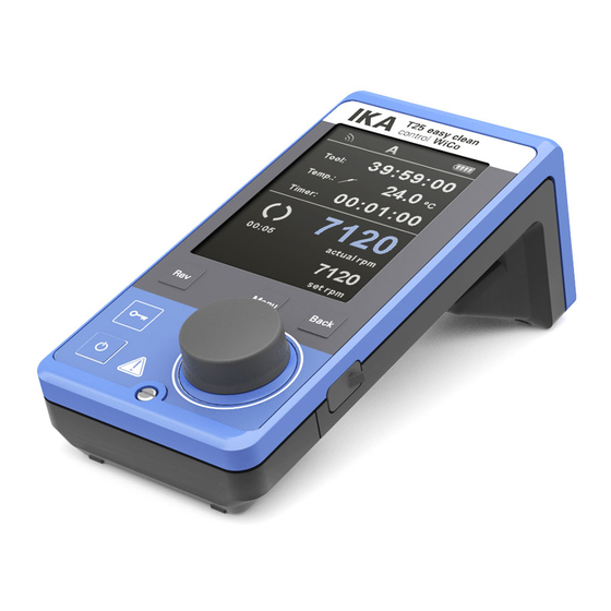
: Bluetooth ® Working with the WiCo This symbol means the drive unit and the WiCo are communicating via Bluetooth ® Control elements of the WiCo: The symbol no longer appears if no Bluetooth ® communication is being performed. : Lock: This symbol means that the function of the buttons and the rotary knob for controlling the WiCo are disabled. - Page 8 LIMIT Speed limit: This symbol indicates upper/low speed limit set for the drive unit. : PC control: This symbol means that either the drive unit or the WiCo is connected to a computer and the drive unit is being controlled from the computer. Then, the buttons and rotary/push knob is no longer available except power switch is pressed.
- Page 9 Navigation menu and menu structure: Navigation menu: Press the "Menu" button (D). Select the menu by turning the rotary/push knob (F) to the right or left to select the desired menu or sub-menu, which can then be selected by pressing the rotary/push knob. ...
- Page 10 Menu structure: Factory settings Dispersing Intermittent Mode Run/Stop Interval Run Time 00:15 [mm:ss] Stop Time 00:15 [mm:ss] Maximum Temperature depending on drive unit Maximum Speed 25000 rpm Tools Tool maintenance time 20:00:00 [hh:mm:ss] for S 25 EC-T... only Reset maintenance time Set maintenance time 40:00:00 [hh:mm:ss] Timer...
- Page 11 Settings Languages English activated Deutsch Display Background Black activated White Brightness Standard Mode 60 % Battery Mode 20 % Firmware Update Info activated Sound Volume 50 % Key Tone Factory Settings Communication Device Name T25 easy clean Bluetooth activated Information Dispersing Intermittent Mode Interval Run...
- Page 12 Menu (details): Dispersing: Intermittent Mode: Symbol rotation Rotor rotation Graph direction direction Factory setting: continuous mode Time ∞ Function “Run/Stop“ is activated: The run time and stop time can be set separately. Time Run-Stop-Run Maximum Temperature: In the “Maximum Temperature“ menu option, the user is allowed to specify a temperature from 0 to 125 °C for the dispersing media. When the dispers- ing media reach the set value, the device stop running.
- Page 13 Operating mode C: In this operating mode, the set speed is saved when the current run comes to an end or the device is switched off, and the value cannot be changed. Tools: Tool maintenance time: In the “Tool maintenance time“ menu option, the user can check the tool Display: maintenance time.
- Page 14 Edit: Edit the selected program parameters. Insert: Start to edit the selected program parameters by pressing on menu op- With the insert option, a new segment will be insert above the selected seg- tion "Edit" with rotary/push knob. The user can edit, delete or insert one ment.
- Page 15 Example for editing the program: PROGRAM 1 PROGRAM 1 Programs Programs Programs Time Interm. Time Interm. hh:mm Mode hh:mm Mode Program 1 Program 1 Program 1 00:00 00:00 Program 2 Program 2 Program 2 Program 3 Program 3 Program 3 Program 4 Program 4 Program 4...
- Page 16 PROGRAM 1 PROGRAM 1 PROGRAM 1 edit PROGRAM 1 edit Time Interm. Time Interm. Time Interm. Time Interm. mm:ss Mode mm:ss Mode mm:ss Mode mm:ss Mode 4000 00:10 3000 00:10 4000 00:10 4000 00:10 00:00 00:00 00:00 00:00 Edit intermittent mode (Yes/No) Edit Delete Insert...
- Page 17 Settings: Safety: Languages: Time Out: The “Languages“ option allows the user to select the desired language In the “Time Out“ menu, the user can set a time limit. This time limit by turning and pressing the rotary/push knob. A tick indicates the lan- applies if there is a communication failure between the drive unit and guage that is set for the system.
-
Page 18: Interface And Output
Connection capability: WiCo to the drive unit. and tear of components and their statistical failure rate. USB micro A Cleaning: For cleaning disconnect the plug-in power supply! Use only cleaning agents which have been approved by IKA to clean IKA instruments. Dirt Cleaning agent Dyes... -
Page 19: Error Codes
For repair, please request the “Decontamination Certificate” form IKA Permitted on time or use the download printout of it from IKA website: www.ika.com. Max. communication distance If you require servicing, return the instrument in its original packaging. Stor- (dependent on the building) age packaging is not sufficient. - Page 20 IKA - Werke GmbH & Co.KG Janke & Kunkel-Str. 10 D-79219 Staufen Tel. +49 7633 831-0 Fax +49 7633 831-98 sales@ika.de www.ika.com...
Need help?
Do you have a question about the WiCo T25 Easy Clean Control and is the answer not in the manual?
Questions and answers