TECO E510 Series Instruction Manual
Ac inverter drive speed controller
Hide thumbs
Also See for E510 Series:
- Instruction manual (223 pages) ,
- Quick start manual (9 pages) ,
- Instruction manual (116 pages)
Table of Contents
Advertisement
Advertisement
Table of Contents

Related Manuals for TECO E510 Series


Summary of Contents for TECO E510 Series
-
Page 2: Table Of Contents
E510 Table of Contents Chapter 0 Preface Preface Chapter 1 Safety Precautions Before Power UP During Power UP Before Operation During Operation Inverter Disposal Chapter 2 Part Number Definition Model Part Number Standard Product Specification Chapter 3 Environment & Installation Environment Installation 3.2.1 Installation method... - Page 3 4.1.5 Operation Control Programmable Parameter Groups 4-27 Parameter Function Description 4-77 Specification Description on Built-in PLC Function 4-77 4.4.1 Basic Instruction 4-78 4.4.2 Function of Basic Instruction 4-79 4.4.3 Application Instructions Chapter 5 Troubleshooting and Maintenance Error Display and Corrective Action 5.1.1 Manual Reset and Auto-Reset 5.1.2 Keypad Operation Error Instruction 5.1.3 Special conditions...
-
Page 4: Chapter 0 Preface
Chapter 0 Preface 0.1 Preface To extend the performance of the product and ensure personnel safety, please read this manual thoroughly before using the inverter. Should there be any problem in using the product that cannot be solved with the information provided in the manual, contact Our’s technical or sales representative who will be willing to help you. -
Page 5: Chapter 1 Safety Precautions
Chapter 1 Safety Precautions 1.1 Before Power Up Danger Make sure the main circuit connections are correct Single phase L1(L),L3(N), Three phase L1(L),L2,L3(N) are power-input terminals and must not be mistaken for T1,T2 and T3. Otherwise, inverter damage can result. Caution The line voltage applied must comply with the inverter’s specified input voltage.(See the nameplate) -
Page 6: During Power Up
1.2 During Power Up Danger When the momentary power loss is longer than 2 seconds, the inverter will not have sufficient stored power for its control circuit. Therefore, when the power is re-applied, the run operation of the inverter will be based on the setup of following parameters: •... -
Page 7: Inverter Disposal
Danger To avoid electric shock, do not take the front cover off while power is on. The motor will restart automatically after stop when auto-restart function is enabled. In this case, care must be taken while working around the drive and associated equipment . -
Page 8: Chapter 2 Part Number Definition
Chapter 2 Part Number Definition 2.1 Model Part Number... -
Page 9: Standard Product Specification
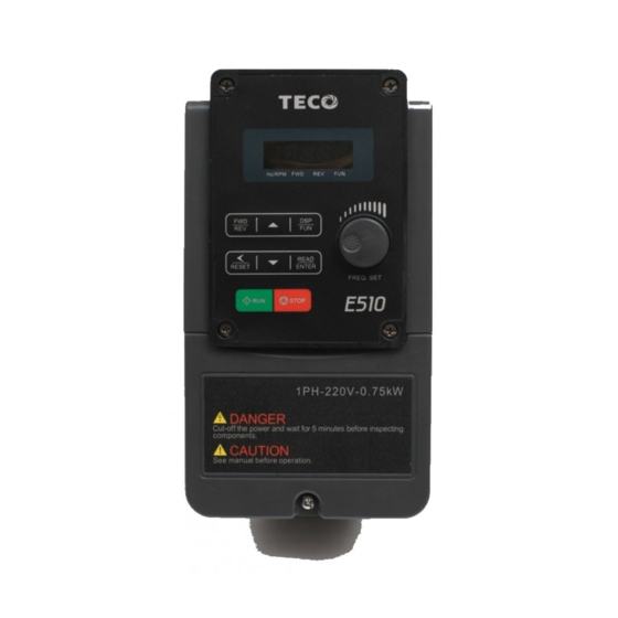
2.2 Standard Product Specification Supply Frequency Filter Power Supply Model (HP) (KW) voltage (Vac) (Hz) Built-in None ◎ E510-2P5-H1F 1 ph, ◎ E510-201-H1F 0.75 Single phase 200~240V ◎ E510-202-H1F (+10%-15%) ◎ E510-203-H1F ◎ E510-2P5-H 1 & 3 ph, ◎ Single/Three E510-201-H 0.75 200~240V... -
Page 10: Chapter 3 Environment & Installation
Chapter 3 Environment & Installation 3.1 Environment Installation environment has a direct effect on the correct operation and the life expectancy of the inverter, Install the inverter in an environment complying with the following conditions: Protection Protection class IP20 Suitable Environment -10~40°C (-10~50°C with fan) Note: –10 ~ 50 ℃... -
Page 11: Installation
The maximum rms symmetrical short circuit ratings are as follows. Device Rating Short circuit Maximum Rating(A) Voltage (Volt) voltage 0.5~20 220V 5000 1~25 440V 5000 3.2 Installation 3.2.1 Installation method (a)Single/Three phase: 200V 0.5~1HP; Single phase: 200V 0.5~1HP; Three phase: 200V 2HP; 400V 1~2HP; Frame1 Frame1(NEMA1) Screw M4... - Page 12 Screw M4 Screw M4 (c)Three phase: 200V 8~10HP; 400V 8~15HP; Frame3 Screw M4 Screw M4 Frame3(NEMA1)
- Page 13 Screw M4 Screw M4...
- Page 14 (d)Three phase: 200V 15~20HP; 400V 20~25HP; Frame4 Screw M5 Screw M5 Frame4(NEMA1) Screw M5 Screw M5...
- Page 15 (e) Three phase:400V 20~25HP; (With Fliter Models) Frame4 Screw M5 Screw M5 Disassembly and assembly steps, As follows: (a)Single/Three phase: 200V 0.5~1HP; Single phase: 200V 0.5~1HP; Three phase: 200V 2HP; 400V 1~2HP; Frame1 Step1:Loosen screw Step2:Remove the terminal cover...
- Page 16 Step3:Wire&Re-install the cover Step4:Tighten the screws Frame 1(NEMA1) Step1: Loosen screw Step2:Remove the terminal cover...
- Page 17 Step3:Wire&Re-install the cover Step4:Tighten the screws (b)Single/Three phase: 200V 2~3HP; Single phase: 200V 2~3HP; Three phase: 200V 5HP; 400V 3~5HP; Frame 2 Step1: Loosen the screws Step2:Remove the terminal cover...
- Page 18 Step3: Wirie&Re-install the cover Step4:Tighten the screws Frame 2(NEMA1) Step1: Loosen the screws Step2: Remove the terminal cover...
- Page 19 Step3: Wire&Re-install the cover Step4:Tighten the screws (c)Three phase: 200V 8~10HP; 400V 8~15HP; Frame 3 Step1: Loosen the screws Step2: Remove the terminal cover 3-10...
- Page 20 Step3: Wirie&Re-install the cover Step4: Tighten the screws Frame 3(NEMA1) Step1: Loosen the screws Step2: Remove the terminal cover 3-11...
- Page 21 Step3: Wirie&Re-install the cover Step4: Tighten the screws (d)Three phase: 200V 15~20HP; 400V 20~25HP; Frame 4 Step1: Loosen the screws Step2: Remove the terminal cover 3-12...
- Page 22 Step3: Wirie&Re-install the cover Step4: Tighten the screws Frame 4(NEMA1) Step1: Loosen the screws Step2: Remove the terminal cover 3-13...
- Page 23 Step3: Wirie&Re-install the cover Step4: Tighten the screws (e) Three phase: 400V 20~25HP; Frame 4(With Filter) STEP1 STEP2 Step1: Loosen the screws Step2: Remove the terminal cover 3-14...
-
Page 24: Installation Space
STEP2 STEP1 Step3: Wirie&Re-install the cover Step4: Tighten the screws 3.2.2 Installation space Provide sufficient air circulation space for cooling as shown in examples below. Install the Inverter on surfaces that provide good heat dissipation, Single unit Installation Install the inverter verticality to obtain effective cooling CONTROL 12cm PANEL... - Page 25 Side by side Installation Provide the necessary physical space and cooling based on the ambient temperature and the heat loss in the panel Extract fan CONTROL PANEL Hz/RPM Hz/RPM READ READ RESET ENTER RESET ENTER Q S T Q S T STOP STOP DANGER...
-
Page 26: Rating Curve
3.2.3 De-rating curves Curves below show the applicable output current de-rate due to setting of carrier frequency and the ambient operating temperatures of 40 and 50 degrees C . Frame1/2/4 (Single phase: 200V: 0.5~3HP; Single /Three phase: 200V: 0.5~3HP; Three phase: 200V: 2/5/15~20HP 400V: 1~5 HP/20~25HP) Frame3(Three phase: 200V 8~10HP;... -
Page 27: Wiring Guidelines
3.3 Wiring Guidelines 3.3.1 Power Cables Supply power cable must be connected to TM1 terminal block, terminals L1(L), L2, L3(N). L1(L) and L3(N) for single phase 230V supply. Motor cable must be connected to TM1 terminals. T1, T2, T3. Warning:- Connection of supply line cable to terminals T1,T2, T3 will result in serious damage to the drive components. -
Page 28: Wiring And Emc Guidelines
3.3.3 Wiring and EMC guidelines For effective interference suppression, do not route power and control cables in the same conduit or trunking. To prevent radiated noise, motor cable should be put in a metal Conduit. Alternatively an armored or shielded type motor cable should be used. For effective suppression of noise emissions the cable armor or shield must be grounded at both ends to the motor and the inverter ground. -
Page 29: Failure Liability
3.3.4 Failure liability Teco bears no responsibility for any failures or damaged caused to the inverter if the recommendations in this instruction manual have not been followed specifically points listed below, If a correctly rated Fuse or Circuit breaker has not been installed between the power source and the inverter. -
Page 30: Considerations For Peripheral Equipment
3.3.5 Considerations for peripheral equipment Ensure that the supply voltage is correct. A molded-case circuit breaker or fused disconnect Power must be installed between the AC source and the inverter Use a molded-case circuit breaker that conforms to the rated voltage and current of the inverter. Do not use the circuit breaker as the run/stop Circuit switch for the inverter. -
Page 31: Ground Connection
3.3.6 Ground connection Inverter ground terminal must be connected to installation ground correctly and according to the required local wiring regulations. Ground cable size must be according to the required local wiring regulations. Ground connection should be as short as possible. Do not share the ground of the inverter with other high current loads (Welding machine, high power motors). -
Page 32: Inverter Exterior
3.3.7 Inverter exterior Exterior (a) Single/Three phase: 200V 0.5~1HP; Single phase: 200V 0.5~1HP; Three phase: 200V 2HP; 400V 1~2HP; E510-Frame 1 E510-Frame 1(NEMA1) 3-23... - Page 33 (b) Single/Three phase: 200V 2~3HP; Single phase: 200V 2~3HP; Three phase: 200V 5HP; 400V 3~5HP; E510-Frame2 E510-Frame2(NEMA1) 3-24...
- Page 34 (c) Three phase: 200V 8~10HP; 400V 8~15HP; E510-Frame 3 E510-Frame 3(NEMA1) 3-25...
- Page 35 (d) Three phase: 200V 15~20HP; 400V 20~25HP; E510-Frame 4 E510-Frame 4(NEMA1) 3-26...
- Page 36 (e) Three phase: 400V 20~25HP; E510-Frame 4 (With Filter) Interior Structure Outlook E510-Frame 1 E510-Frame 2 Control Panel RS485 400V 3.7kW 200V 0.75kW RS485 Ground termina 3-27...
- Page 37 E510-Frame 3 E510-Frame 4 Control Panel RS485 RS485 400V 5.5kW 400V 15kW Ground terminal 3-28...
-
Page 38: Specifications
3.4 Specifications 3.4.1 Product Specifications 220V Class:Single phase Model:E510-□□□- H1F Horse power (HP) 0.75 Suitable motor capacity (KW) 10.5 Rated output current (A) 2.90 4.00 Rated capacity (KVA) Single Phase:200~240V,50/60HZ Input voltage range(V) +10 %-15% Allowable voltage fluctuation Three phase: 0~240V Output voltage range(V) 23.9 Input current (A)*... - Page 39 400VClass:Three phase Model:E510-□□□- H3 Horse power (HP) 0.75 Suitable motor capacity (KW) Rated output current (A) Rated capacity (KVA) Three phase:380~480V,50/60HZ Input voltage range(V) +10 %-15% Allowable voltage fluctuation Three phase:0~ 480V Output voltage range(V) 11.6 Input current (A)* Inverter net weight (KG) Allowable momentary power loss time (S) IP20 Enclosure...
-
Page 40: General Specifications
3.4.2 General Specifications Item E510 Control Mode V/F Control, Vector Control Output Frequency 0.01~650.00Hz Starting Torque 150%/1Hz(Vector) Speed Control Range 1:50 Digital input : 0.01Hz Setting resolution Analog input :0.06Hz/60Hz Keypad : Set directly with▲▼ keys or the VR on the Frequency keypad External Input Terminlas:... - Page 41 direct start after power up and error recovery ,parameter lock up All frames include brake transistor Standard built-in RS485 communication (Modbus), Communication control One to one or One to many control. -10~50℃ (Note1) Operating temperature -20~60℃ Storage temperature 95% RH or less (no condensation) Humidity (Compliance with IEC 60068 - 2-78)
-
Page 42: Standard Wiring
3.5 Standard wiring 3.5.1 Single phase: Magnetic Molded-case circuit contactor breaker MCCB L1(L) Induction Magnetic Inverter Power Motor contactor output source L3(N) Molded-case circuit breaker Ground 1:Data+ 2:Data- CON2 3:Data+ 4:Reserved RS485 5:Reserved FWD (Run/Stop) 6:Data- 7:5V REV (Run/Stop) 8:GND Speed Control Reset COM (NPN) -
Page 43: Single/ Three Phase
3.5.2 Single /Three phase: Model: 200V: E510-2P5-H/ E510-201-H/ E510-202-H/ E510-203-H 3-34... -
Page 44: Three Phase
3.5.3 Three phase Three phases power input MCCB Induction Inverter Motor L1(L) output Power source L3(N) Ground 1:Data+ 2:Data- CON2 3:Data+ 4:Reserved RS485 5:Reserved FWD (Run/Stop) 6:Data- 7:5V REV (Run/Stop) 8:GND Speed Control Reset COM (NPN) + 24V(PNP) Safety Function Input AI1 AI2 0 ~10V Frequency... -
Page 45: Terminal Description
3.6 Terminal Description 3.6.1 Description of main circuit terminals Terminal symbols TM1 Function Description L1(L) Main power input, L1(L)/L2/L3(N) L3(N) Inverter output, connect to U/V/W terminals of motor Braking resistor connection terminal: Used in applications when it is required to stop a high inertia load rapidly. - Page 46 Single/Three phase:200V 2~3HP; Three phase:200V 5HP; 400V 3~5HP; L1(L) L3(N) Frame3& Frame4 Three phase:200V 8~20HP; 400V 8~25HP 3-37...
-
Page 47: Control Circuit Terminal Description
3.6.2 Control circuit terminal description Type Terminal Terminal function Signal level Forward─Stop (Preset), Multi function input terminal Reverse─Stop (Preset), Multi function input terminal 24 VDC, 8 mA, Optical Digital Preset Speed0(5-02),Multi function input terminal coupling input isolation(Max,voltage30 Vdc, Preset Speed1(5-03), Multi function input terminal signal Input impedance 3.3kΩ) Preset Speed2(5-05), Multi function input terminal... -
Page 48: Outline Dimensions
JUMPER function description Jumper Symbol Function Signal Reference Note NPN Input NPN/PNP Factory defult setting selectable PNP Input 0~20mA Analog Set parameters signal External signal type 00-05/00-06 selection to 2 or 3 (external analog input) to 0~10VDC Analog become effective signal 3.7 Outline Dimensions mm(inch) - Page 49 Frame1 Single/Three phase: 200V 0.5~1HP; Single phase: 200V 0.5~1HP; Three phase: 200V 2HP; 400V 1~2HP; 2-d1 2- Q 1 2- Q 2 2-d2 Unit:mm(inch) Dimensions Model Tolerance table (KG) E510-2P5-H E510-201-H ± 0 ~ 10 E510-2P5-H1F ± E510-201-H1F 10 ~ 50 90.6 163.6 146.8...
- Page 50 Frame2 Single/Three phase: 200V 2~3HP; Single phase: 200V 2~3HP; Three phase: 200V 5HP; 400V 3~5HP; 2-d1 2- Q 1 2-d2 2- Q 2 Unit:mm(inch) Dimensions Model Tolerance table (KG) E510-202-H E510-203-H E510-202-H1F ± 0 ~ 10 E510-203-H1F ± 10 ~ 50 128.7 187.6 177.6...
- Page 51 Frame3 Three phase: 200V 8~10HP; 400V 8~15HP; 2-d1 2- Q 1 2- Q 2 2-d2 Unit:mm(inch) Dimensions Tolerance Model (KG) table E510-208-H3 ± E510-210-H3 0 ~ 10 ± E510-408-H3 10 ~ 50 50 ~ E510-410-H3 ± 186.9 260.9 249.8 84.7 (7.36) (6.92) (6.89)
- Page 52 Frame4 Three phase: 200V 15~20HP; 400V 20~25HP; 2- Q 1 2- Q 2 Unit:mm(inch) Dimensions Tolerance Model (KG) table E510-215-H3 ± 0 ~ 10 ± 10 ~ 50 E510-220-H3 ± 50 ~ 100 224.6 321.6 303.5 330.9 198.3 187.5 192.5 100 ~ 10.5 (8.84)
- Page 53 Frame4( ) Three: 400V 20~25HP; Built-in EMC filter Unit:mm(inch) Dimensions Tolerance Model table ± 0 ~ 10 E510-420-H3F ± 10 ~ 50 ± 224.6 435.8 303.5 330.9 198.3 187.5 192.5 64.2 192.5 50 ~ 100 100 ~ (8.84) (8.15) (8.15) (17.16) (11.95) (13.03)
- Page 54 Frame1(NEMA1) Single/Three phase: 200V 0.5~1HP; Single phase: 200V 0.5~1HP; Three phase: 200V 2HP; 400V 1~2HP; 2-d1 2- Q Unit:mm(inch) Dimensions Model Tolerance table (KG) E510-2P5-H E510-201-H ± E510-2P5-H1F 0 ~ 10 ± 10 ~ 50 E510-201-H1F 90.65 80.5 186.2 189.2 146.8 137.8 140.8...
- Page 55 Frame2(NEMA1) Single/Three phase: 200V 2~3HP; Single phase: 200V 2~3HP; Three phase: 200V 5HP; 400V 3~5HP; 2-d1 2- Q Unit:mm(inch) Dimensions Model Tolerance table (KG) E510-202-H E510-203-H ± E510-202-H1F 0 ~ 10 ± E510-203-H1F 10 ~ 50 128.7 118.3 210.6 213.6 147.8 133.8 141.8...
- Page 56 Frame3(NEMA1) Three phase: 200V 8~10HP; 400V 8~15HP; 2- Q 2-d1 Unit:mm(inch) Dimensions Model Tolerance table (KG) E510-208-H3 E510-210-H3 E510-408-H3 ± 0 ~ 10 ± 10 ~ 50 E510-410-H3 186.9 76.7 170.6 ± 50 ~ 100 ± (7.36) (6.89) (11.47) (11.65) (7.67) (7.24) (7.44)
- Page 57 Frame4(NEMA1) Three phase: 200V 15~20HP; 400V 20~25HP; 2- Q 2-d1 Unit:mm(inch) Dimensions Model Tolerance table (KG) E510-215-H3 ± 0 ~ 10 E510-220-H3 ± 10 ~ 50 E510-420-H3 224.6 350.1 355.1 198.3 187.5 192.5 ± 50 ~ 100 ± (8.84) (8.15) (13.78) (13.98) (7.81)
-
Page 58: Emc Filter Disconnection
3.8 EMC Filter Disconnection EMC filter may be disconnected: Inverter drives with built-in EMC filter are not suitable for connection to certain type of supply systems, such as listed below; in these cases the RFI filter can be disabled. In all such cases consult your local electrical standards requirements. IT type supply systems (ungrounded) &... -
Page 59: Chapter 4 Software Index
Chapter 4 Software Index 4.1 Keypad Description 4.1.1 Operator Panel Functions Type Item Function Frequency Display, Parameter, voltage, Current, Main digital displays Temperature, Fault messages. Hz/RPM: ON when the frequency or line speed is displayed. OFF when the parameters are displayed. Digital FWD: ON while the inverter is running forward. -
Page 60: Digital Display Description
4.1.2 Digital display Description Alpha numerical display format Digit Letter Letter Symbol ° Digital tube lights flashing instructions Actual output frequency Set frequency Digits are lit Continually Preset digits flashing Selected digit flashing... - Page 61 LED display examples Display Description In stop mode shows the set frequency In run mode shows the actual output frequency Selected Parameter Parameter Value Output Voltage Output Current in Amps DC Bus voltage Temperature PID feedback Value Error display ( 0~1000) Analogue Current / Voltage AI1 / AI2 .
-
Page 62: Digital Display Setup
4.1.3 Digital display set up On power up digital display screens will be as shown below. DSP/ DSP/ 2sec later parameter frequency Power supply User selectable display formats: 12- 00 Display Mode Range High Each of the above 5 digits can be set to any of the selections below from 0 to 8 【0】:Disable display 【1】:output Current 【2】:output Voltage 【3】:DC voltage 【5】:PID feedback... - Page 63 Example 2. Set parameter 12- 00=【12345】 to obtain the display format shown below. DSP/ DSP/ DSP/ Temperature DC voltage < 4 > < 3 > DSP/ PIDfeedback Output Voltage DSP/ < 5 > < 2 > 2sec later Output Current Parameter Display: Power supply DSP/...
- Page 64 Example2: Modifying the frequency from keypad in run and stop modes. Modify frequency in stopping Modify frequency in operating Power Supply Power supply 2sec later 2sec later Set frequency display Set frequency display Press RUN Short time press </RESET once Actual frequency Short time press </RESET once...
- Page 65 4.1.5 Operation Control Stop Actual output frequency Power REV FWD Stop...
- Page 66 4.2 Programmable Parameter Groups Parameter Group No. Description Group 00 Basic Parameters Group 01 V/F Pattern Selections and Setup Group 02 Motor Parameters Group 03 Multi Function Digital Inputs/Outputs Group 04 Analog Signal Inputs/Output Group 05 Preset Frequency Selections Group 06 Auto Run Function(Auto Sequencer) Group 07 Start/Stop Command Setup...
- Page 67 G ro up 00- Basic parameters Factory Description Range Unit Note Setting 0:V/F Mode 00-00 Control Mode Selection 1:Vector Mode 00-01 Reserved 0:Keypad 1:External Run/Stop Control Main Run Command 00-02 Source Selection 2:Communication 3:PLC 0:Keypad Alternative Run Command 00-03 1:External Run/Stop Control Source Selection 2:Communication 0: Forward/Stop-Reverse/Stop...
- Page 68 G ro up 01- V/F Pattern selection & Setup Factory Description Range Unit Note Setting 01-00 Volts/Hz Patterns 1~18 200V:170.0~264.0 V/F Max voltage 220.0/440.0 01-01 400V:323.0~528.0 Max Frequency 0.20 ~ 650.00 50.00/60.00 01-02 01-03 Max Frequency Voltage Ratio 0.0 ~ 100.0 100.0 Mid Frequency 2 0.10 ~ 650.00...
- Page 69 Group 03- External Digital Inputs and Relay Output Functions Factory Description Range Unit Note Setting 03-00 Multifunction Input Term. S1 0:Forward/Stop Command 1:Reverse/Stop Command 03-01 Multifunction Input Term. S2 03-02 2:Preset Speed 0(5-02) Multifunction Input Term. S3 03-03 3:Preset Speed 1(5-03) Multifunction Input Term.
- Page 70 Group 03- External Digital Inputs and Relay Output Functions Factory Description Range Unit Note Setting Output Relay RY1 0:Run 03-11 ( Terminals R1A,R1B, R1C ) 1:Fault 2:Setting Frequency Reached 3:Frequency Reached. Set by (3-13±3-14) 4:Output Frequency Detection1(> 3-13) 5:Output Frequency Detection2(< 3-13) 6:Auto Restart 7:Momentary AC Power Loss...
- Page 71 Group 04- Analog signal inputs / Analog output Factory Description Range Unit Note Setting 0~10V 0~10V or(0~20mA) or(0~20mA) 0~10V 2~10V 04-00 Analog Input Signal Type or(0~20mA) or(4~20mA) Select (AI1/AI2) 2~10V 0~10V or(4~20mA) or(0~20mA) 2~10V 2~10V or(4~20mA) or(4~20mA) AI1 Signal Verification Scan 1~200 04-01 Rate...
- Page 72 Group 05- Preset Frequency Selections Factory Description Range Unit Note Setting 0: Common Accel/Decel Accel/Decel 1 or 2 apply to all speeds Preset Speed Control 05-00 1: Individual Accel/Decel for each preset speed Mode Selection 0-15 apply to the selected preset speeds (Acc0/Dec0~Acc15/Dec15) Preset Speed 0 05-01...
- Page 73 Group 05- Preset Frequency Selections Factory Description Range Unit Note Setting Preset 05-40 10.0 Speed11-Dectime Preset 05-41 10.0 Speed12-Acctime Preset 05-42 10.0 Speed12-Dectime Preset 05-43 10.0 Speed13-Acctime Preset 05-44 10.0 Speed13-Dectime Preset 05-45 10.0 Speed14-Acctime Preset 05-46 10.0 Speed14-Dectime Preset 05-47 10.0 Speed15-Acctime...
- Page 74 Group 06- Auto Run Function (Auto Sequencer) Factory Description Range Unit Note Setting Auto _ Run Mode 06-06 0.00 Frequency Command 6 Auto _ Run Mode 06-07 0.00 Frequency Command 7 Auto _ Run Mode 06-08 0.00 Frequency Command 8 Auto _ Run Mode 06-09 0.00...
- Page 75 Group 06- Auto Run Function (Auto Sequencer) Factory Description Range Unit Note Setting Auto_ Run Mode 06-27 Running Time Setting Auto_ Run Mode 06-28 Running Time Setting Auto_ Run Mode 06-29 Running Time Setting Auto_ Run Mode 06-30 Running Time Setting Auto_ Run Mode 06-31 Running Time Setting...
- Page 76 Group 07- Start/Stop Command Setup Factory Description Range Unit Note Setting 0: Momentary Power Loss and Restart Disable Momentary Power Loss 07-00 and Restart 1: Momentary Power Loss and Restart Enable Auto Restart Delay 07-01 0.0~800.0 Time Number of Auto Restart 07-02 0~10 Attempts...
- Page 77 Group 08- Drive & Motor Protection Functions Factory Description Range Unit Note Setting xxxx0: Enable Trip Prevention During Acceleration xxxx1: Disable Trip Prevention During Acceleration xxx0x: Enable Trip Prevention During Deceleration xxx1x: Disable Trip Prevention During Deceleration Trip Prevention 00000 08-00 xx0xx: Enable Trip Prevention in Run Selection...
- Page 78 Group 08- Drive & Motor Protection Functions Factory Description Range Unit Note Setting 0: Over Torque Detection Disabled Over Torque Detection 08-13 1: Detected After the Setting Frequency Control 2: Detected When Running 0:Stop Output After Over Torque Detection (Free Run to Stop) Over torque protection 08-14...
- Page 79 Group 10- PID Function Setup Factory Description Range Unit Note Setting 0:Potentiometer on Keypad 1: Analog Signal Input. (AI1) PID Target Value Selection 2: Analog Signal Input. (AI2) 10-00 (When 00-03\00-04=6 This 3: Frequency Set by Communication Function is Enabled) 4: Keypad Frequency Parameter 10-02 0:Potentiometer on Keypad...
- Page 80 Group 11- Performance Control Functions Factory Description Range unit Note Setting 0: Reverse Command is Enabled 11-00 Reverse Operation Control 1: Reverse Command is Disabled 11-01 Carrier Frequency (kHz) 1~16 0: Mode0, 3Phase PWM modulation 1: Mode1, 2Phase PWM modulation 11-02 Carrier Mode Selection 2: Mode2, 2Phase Random PWM...
- Page 81 Group 12 Digital Display & Monitor Functions Factory Description Range Unit Note Setting 0:xxx-- PID Feedback Display Unit 12-02 1:xxxpb(pressure) Setting 2:xxxfl(flow) Custom Units (Line Speed) 12-03 0~65535 1500/1800 Value 0:Drive Output Frequency is Displayed 1: :Line Speed.Integer.(xxxxx) 2:Line Speed.One Decimal Place. Custom Units (Line Speed) (xxxx.x) 12-04...
- Page 82 Group 12 Digital Display & Monitor Functions Factory Description Range Unit Note Setting Frequency Command when ---- 12-15 Fault Appeared Group 13 Inspection & Maintenance Functions Factory Description Range unit Note Setting 13-00 Drive Horsepower Code ---- Software Version ---- *3*4 13-01 Fault Log (Latest 3...
- Page 83 Group 14 PLC Setting function Factory Description Range unit Note Setting Setting Value1 of T1 14-00 0~9999 Setting Value1 of T1 (mode 7) 14-01 0~9999 14-02 Setting Value1 of T2 0~9999 14-03 Setting Value1 of T2 (mode 7) 0~9999 14-04 Setting Value1 of T3 0~9999 14-05...
- Page 84 Group 15 PLC Monitoring function Factory Description Range unit Note Setting 15-00 Current Value of T1 0~9999 Current Value of T1(mode 7) 15-01 0~9999 15-02 Current Value of T2 0~9999 15-03 Current Value of T2(mode 7) 0~9999 15-04 Current Value of T3 0~9999 15-05 Current Value of T3(mode 7)
- Page 85 4.3 Parameter Function Description 00 - Basic Parameters Group 00- 00 Control Mode Selection 【0】:V/F Mode Range 【1】:Vector Mode To select the appropriate vector or V/F control mode according to the load characteristics. If V/F mode is selected, please set parameters, group1 to comply with the load features. Vector is best suited to control the general load or rapidly-changed torque load.
- Page 86 00- 07 Main and Alternative Frequency Command Modes 【0】: Main or Alternative Frequency. Range 【1】: Main Frequency + Alternative Frequency When 00 - 07 = 【0】, ,the frequency source is set by the Main frequency parameter 00-05 ( Default) or by the Alternative frequency parameter 00-06. Use any of the external terminals S1 to S6 and set the relevant parameter 03-00 to 03-05 =【13】to switch from Main to Alternative source..
- Page 87 00-14 Acceleration Time 1 【0.1~3600.0】 s Range 00-15 Deceleration Time 1 【0.1~3600.0】 s Range 00-16 Acceleration Time 2 【0.1~3600.0】 s Range 00-17 Deceleration Time 2 【0.1~3600.0】 s Range Preset Acceleration and Deceleration times set by above parameters are the time taken for the output frequency to ramp up or ramp down between the Upper and the lower frequency limits.
- Page 88 01- V/F Pattern selections & setup 01- 00 Volts/Hz Patterns (V/F) 【0~18】 Range Set 01-00 to one of the following preset V/f selections 【0~17】according to the required application. Parameters 01-02~01-09 are not applicable. Six fixed V/f patterns are shown below.【1~8】for 50 Hz systems and 【9~17】for 60 Hz TYPE 50Hz 60Hz...
- Page 89 (V) 100% is the maximum output voltage. B, C point preset % settings will be as table below: 01- 00 B(Xb) C(Xc) 0 / 9 7.5% 4.5% 1 / 10 10.0% 7.0% 11.0% 8.5% 12.0% 9.5% 17.5% 4.0% 25.0% 5.0% 11.0% 8.0% 12.0%...
- Page 90 (V)% 01-03 (Vmax) 01-05 (Vmid2) 01-07 (Vmid1) 01-09 (Vmin) 01-08 01-06 01-04 01-02 650.00 01-10 Volts/Hz Curve Modification (Torque Boost) 【0 ~ 10.0】% Range Inverter output V / F curve settings for points B, C can be adjusted by parameter 01-10 to improve the output torque.
- Page 91 02- Motor parameters 02- 00 Motor No Load Current Range ---- 02- 01 Motor Rated Current Range ---- 02- 02 Motor Rated Slip Compensation 【0.0 ~ 200.0】(%) Range 02- 03 Motor Rated Speed Range ---- When the load causes the actual motor speed to be reduced below the speed set by inverter output frequency (Slip) , parameter 02-02 Slip compensation can be used to correct the speed.
- Page 92 In vector mode, selected by parameter 00-00=【1】, set the motor name plate data in parameters 02-01、02-03~02-06 then activate the out auto tune function by setting parameter 02-14 = 1.. Auto tune function will set the inverter to run with the specific motor connected to obtain the best motor performance.
- Page 93 (FWD/STOP) (REV/STOP) E510 ※Note: If both forward and reverse commands are ON, it will be treated as a STOP. 1B) 2-wire method. Mode 2. Example: RUN/STOP and REV/FWD from two inputs (S1&S2) Set 00- 04=【1】; S1:03- 00=【0】(RUN/STOP); S2:03- 01=【1】(REV/FWD); ( RUN /STOP) ( REV/FWD) E510 1C) 3-wire method.
- Page 94 S1(RUN) S2(STOP) S3(FWD/REV) E510 2. 03- 00~03- 05=【2,3,4,5】Preset speed selections Combination of any four terminals from S1~ S6 can be used to select preset speeds 0 to 15 according to the table below. Preset speed 0-15 and the related acceleration/decelerating times should be set in parameter group 5. For example timing diagram refer to Group 5 description Function setting and state of any four...
- Page 95 3. 03- 00~03- 05=【6, 7】Forward/ Reverse JOG When an input terminal is set to function【6】and is turned on, inverter will work in jog forward mode. When an input terminal is set to function【7】and is turned on, inverter will work in jog reverse mode. Note: If jog forward and jog reverse function is enabled at the same time, inverter will enter stop mode.
- Page 96 50Hz(upper frequency) 25Hz( target frequency) Actual 5S(accelerating accelerating time 1) Diagram b time 1 Diagram b: The actual accelerating time : target frequency 25Hz × × actual accelerating time accelerating time 1= upper frequency 50Hz 6. 03- 00~03- 05=【11】Disable Acc/Dec function When an input terminal is set to function【11】and is turned on, acceleration and deceleration function will be disabled and the frequency at the time is maintained.
- Page 97 11. 03- 00~03- 05=【16】Disable PID Function When an input terminal is set to function【16】and is turned on, PID functions is disabled, if it is turned off , PID function is enabled again. 12. 03- 00~03- 05=【17】Reset When a failure that can be manually reset occurs ,turn on a terminal with function 【17】, the failure will be reset.
- Page 98 2. The inverter will run at full speed up to the maximum of inverter running frequency. 3. None protectional functions, including ES/BB or stop signal sent by operation panel, stop key, can stop the inverter when entering into firemode, usless the main power is lost or cut off or the inverter itself breaks down.
- Page 99 03- 07 Up/Down Keep Frequency Status after Stop Command 【0】: After a stop command in Up/Down mode, the preset frequency is held as the inverter stops,and the UP/Down function is disabled. Range 【1】After a stop command in Up/Down mod, the preset frequency is reset to 0 Hz as the inverter stops.
- Page 100 【16】:Final count value reached (3-22~23) 【17】:Initial count value reached (3-22~23) 【18】:PLC status indicator (00-02) 【19】:PLC control 03-13 Frequency Reached Level 【0.00~650.00】 Hz Range 03-14 Frequency Reached Detection Range (±) 【0.00~30.00】 Hz Range Output relay RY function descriptions: 1) 03-11/03-12 =【0】. RY will be ON with Run signal. 2) 03-11/03-12 =【1】.
- Page 101 5) 03-11=【4】. RY will be on as soon as the output frequency > preset frequency reached Setting (03-13) 6) 03-11=【5】. RY will be on as soon as the output frequency < Preset Frequency Reached Setting (03-13) 03-15 Preset output current reached 【0.1~15.0】...
- Page 102 03-17 Brake Release Level 【0.00~20.00】 Hz Range 03-18 Brake Engage Level 【0.00~20.00】 Hz Range If 03-11 =【14】 In accelerating mode. RY will be ON as soon as the actual output frequency reaches the external Brake release level set in parameter 03-17. In decelerating mode, RY will be OFF as soon as the actual output frequency reaches the external Brake engage level set in parameter 03-18.
- Page 103 0: representative external multi-function input terminals 1:Representative internal multi-function input terminals ※ Note:S1, S2 Selected as internal multi-function input terminals, S3, S4, S5, S6 Selected as external multi-function input terminals. The setting:03-02=000011. 03- 21 Action to Set the Internal Multi-Function Input Terminals 【0~63】...
- Page 104 When 03-24=1,if output current< low current detection level, after a detection time set by 03-26 the, keypad display will show error: ud-c. 04- External Analog Signal Input / Output Functions 04- 00 Analog Voltage & Current Input Selections AI1/AI2 Range 0~10V(0~20mA)...
- Page 105 sources. Long scan times will result in slower response time. AI1.Analog Voltage input scaling examples by adjusting Gain, Bias & Slope parameters (04-02~04-05) (1) Positive Bias type (04-04= 0) and effects of modifying Bias amount by parameter 04-03 and Slope type with parameter 04-05 are shown in Fig 1&2.
- Page 106 (3)Offset bias set to 0% (04-03) and effect of modifying Analog Gain ( 04-02), Bias type ( 04-04) and slope type( 04-05) are shown in shown Fig 5&6. Figure5: Figure6: 04- 02 04- 03 04- 04 04- 05 04- 02 04- 03 04- 04 04- 05...
- Page 107 04-11 Analog Output (AO) Function Selection. 【0】:Output Frequency Range 【1】:Frequency Command 【2】:Output Voltage 【3】:DC Bus Voltage 【4】:Output Current Example: Set 04-11 required according to the table below. 04-11 Xmax 【0】 Output frequency upper frequency limit 【1】 Frequency Setting upper frequency limit 【2】...
- Page 108 0-100Hz 0-200Hz 0-50Hz AGND AGND AGND Ratio C Ratio B Ratio A Master Parameter Preset: 00-05=2 00-05=2 00-05=2 00-12=100 00-12=200 00-12=50 04-16=1 04-16=1 04-16=1 Frequency 200Hz upper limit ( Hz) 100Hz C 50Hz Analog Input Signal Master 4-50...
- Page 109 05- Preset Frequency Selections 05- 00 Preset Speed Control mode Selection 【0】: Common Accel/Decel Range 【1】: Individual Accel/Decel for each preset speed 0-15 05- 01 Preset Speed 0 (Keypad Freq) 05- 02 Preset Speed 1 05- 03 Preset Speed 2 05- 04 Preset Speed 3 05- 05...
- Page 110 When 05- 00 =【0】, Accel /Decel 1 or 2 set by parameters 00-14/00-15 or 00-16/00-17 apply to all speeds. When 05- 00 =【1】, When 05- 00 =【1】Individual Accel/Decel apply to each preset speed 0-15. Parameters 05-17 to 05-48. Formula for calculating acceleration and deceleration time: Maximum output frequency = parameter 01-02 when programmable V/F is selected by 01- 00=【18】...
- Page 111 05-03 05-02 Preset speed2 05-01 Preset speed1 Preset speed0 STOP STOP STOP command When the run command is On/Off, acceleration and deceleration times for each cycle can be calculated as below:- time unit is in seconds. − × − − ×...
- Page 112 05-03 05-02 Preset speed2 05-04 05-06 Preset speed1 05-01 Preset speed3 … … Preset Preset speed5 speed0 05-05 Preset speed4 STOP command When the run command is continuous, acceleration and deceleration times for each segment can be calculated as below:- −...
- Page 113 06- 04 Auto _ Run Mode Frequency Command 4 06- 05 Auto _ Run Mode Frequency Command 5 06- 06 Auto _ Run Mode Frequency Command 6 06- 07 Auto _ Run Mode Frequency Command 7 06- 08 Auto _ Run Mode Frequency Command 8 06- 09 Auto _ Run Mode Frequency Command 9 06- 10...
- Page 114 direction are set by parameters 06-16 and 06-32. Auto RUN ( Auto Sequencer) examples are shown in the following pages:- Example 1. Single Cycle (06- 00=1,4) The inverter will run for a single full cycle based on the specified number of sequences, then it will stop. In this example 4 sequences are set, three in forward direction and one in Reverse.
- Page 115 The speed of final step will be held to run. Auto Run Mode 06- 00 = 【3】(or【6】), Frequency 05- 01=【15】Hz, 06- 01=【30】Hz, 06- 02=【50】Hz, 06- 15=【20】Hz, Sequence Run Time 06-16=【20】s, 06-17=【25】s, 06-18=【30】s, 06-31=【40】s, Direction 06-32=【1】, 06-33=【1】, 06-34 = 【1】, 06-47=【1】(FWD), Unused Sequence Parameters 06-04~06- 15=【0】Hz ,06-19~06-30=【0】s ,06-35~06-46 = 【0】...
- Page 116 07- Start/Stop Command Setup 07- 00 Momentary power loss and restart 【0】:Momentary Power Loss and Restart Disable Range 【1】:Momentary Power Loss and Restart Enable If the input power supply due to sudden increase in supply demand by other equipment results in voltage drops below the under voltage level, the inverter will stop its output at once.
- Page 117 07- 06 DC Injection Brake Start Frequency (Hz) 【0.10 ~ 10.00】Hz Range 07- 07 DC Injection Brake Level (%) 【0.0~ 150.0】% Range 07- 08 DC Injection Brake Time(Seconds) 【0.0 ~ 25.5】Sec Range 07- 08 / 07- 06 set the DC injection brake duration and the brake start frequency, as shown below: Frequency 07-06 07-08...
- Page 118 07-13 Main Circuit Low Voltage Detection 220V Class【150.0~210.0】 Range 440V Class【300.0~420.0】 Kinetic Energy Back-up Deceleration Time(KEB) 07-14 【0.0】: Disable Range 【0.1~25.0】: KEB Deceleration Time 07-14 = 0 KEB function disable 07-14 ≠ 0 KEB function enable Example: 220V system Power Off Power On External power on Signal when 03-00~03-05=27...
- Page 119 08- Protection function group 08- 00 Trip Prevention Selection 【xxxx0】:Enable Trip Prevention During Acceleration 【xxxx1】:Disable Trip Prevention During Acceleration 【xxx0x】:Enable Trip Prevention During Deceleration 【xxx1x】:Disable Trip Prevention During Deceleration Range 【xx0xx】:Enable Trip Prevention in Run Mode 【xx1xx】:Disable Trip Prevention in Run Mode 【x0xxx】:Enable over voltage Prevention in Run Mode 【x1xxx】:Disable over voltage Prevention in Run Mode 08- 01...
- Page 120 Minute Current 08- 07 OH Over Heat Protection 【0】:Auto (Depends on heat sink temp.) Range 【1】:Operate while in RUN mode 【2】:Always Run 【3】:Disabled 08- 07=【0】: Cooling fan runs as the inverter detects temperature rise. 08- 07=【1】: Cooling fan runs while the inverter is running. 08- 07=【2】: Cooling fan runs continuously.
- Page 121 When 08-12= 【 0】 : Overload protection for motors used in general purpose applications, as long as the load demand is less than 103% of the rated current, the motor continues to run. If the load is larger than 150% rated current, the motor will run for 1 minute only. (Refer to following curve1 on page 4-61).
- Page 122 09- Communication function setup 09- 00 Assigned Communication Station Number 【1 ~ 32】 Range 09-00 to sets the communication station number when there is more that one unit on the communication network. Up to 32 Slave units can be controlled from one master controller such as a PLC.
- Page 123 10-PID function Setup PID block diagram 1 、2 Delay device 10-03=0 P(10-05) Postive (10-10) Or stop 10-00 Negative I( 10-06) (10-15) 3 、4 Offset Sleep/ (10-08 1、3 10-03 Wake 10-09) D(10-07) PID frequency (00-12) function output 2、4 communication 10-03 2、4 read D(10-07) 10-21...
- Page 124 For 10-03 = 1 or 2, If the deviation is positive, the output frequency increases and, vice versa. For 10-03 = 3 or 4, If the deviation is positive, the output frequency decreases, vice versa. 10- 04 Feedback Gain Coefficient 【0.00 ~ 10.00】...
- Page 125 10-18 PID Sleep Function Delay Time 【0.0 ~25.5】Sec Range 10-19 PID Wake up Frequency Level 【0.00 ~ 650.00】Hz Range 10-20 PID Wake Up Function Delay Time 【0.0 ~ 25.5】Sec Range When PID output frequency is less than the sleep threshold frequency and exceeds the time of sleep delay, the inverter will decelerate to 0 and enters PID sleep mode.
- Page 126 11 Performance Control Functions 11- 00 Prevention of Reverse operation 【0】:Reverse command is enabled Range 【1】:Reverse command is disabled 11-00=1, the reverse command is disabled. 11- 01 Carrier Frequency Range 【1~16】KHz While IGBT-driven inverter can provide low-noise working environment, the high frequency devices have carrier frequency waveform cutting, it may interfere with external electronic device, even caused vibration when connected with motor, then need to adjust the carrier frequency.
- Page 127 11- 04 S-Curve Acc 1 11- 05 S-Curve Acc 2 11- 06 S-Curve Dec 3 11- 07 S-Curve Dec 4 【0.0 ~ 4.0】Sec Range Use S Curve parameters where a smooth acceleration or deceleration action is required, this will prevent possible damage to driven machines by sudden acceleration/deceleration. Actual output frequency...
- Page 128 OV (over voltage), to avoid over voltage due to regeneration the output frequency will be increased.. Regeneration avoid ance can be set according to the selections above. Example: Regeneration avoidance during acceleration. Set value of 11-14 Vpn(DCV) outputfre quency In Regeneration avoidance operation Example: Regeneration avoidance during constant speed.
- Page 129 Sets the regeneration avoidance frequency limit. 11- 16 Regeneration Avoidance Voltage Gain 【0~200】 Range 11- 17 Regeneration Avoidance Frequency Gain 【 0~200 】 Range 11-16/11-17 Representative responsiveness of Regeneration avoidance action, increase the set value, will improve the response to voltage changes on the bus, but the output frequency may be unstable.
- Page 130 12- 04≠0,line speed is displayed while the inverter is running or stopped. 12- 05 Inputs and output Logic status display (S1 to S6) & RY1~2 Range Read only(Panel read only) When any of S1 ~ S6 is turned on, corresponding segments on the digital display digits will be on. When relay output RY1/RY2 are on, the corresponding digit will be on as shown below.
- Page 131 13 Inspection & Maintenance Functions 13- 00 Drive Horsepower Code Range ---- Inverter Model: Inverter Model: 13- 00 show 13- 00 show E510-2P5-XXX E510- 401-XXX E510-201-XXX E510- 402-XXX E510-202-XXX E510- 403-XXX E510-203-XXX E510- 405-XXX E510-205-XXX E510- 408-XXX E510-208-XXX E510- 410-XXX E510-210-XXX E510- 415-XXX E510-215-XXX...
- Page 132 Setting Parameter lock key number example: Step1: < /EN T ▲ 1st entry ▼ < /EN T Step2: Set Password failed < /EN T ▼ ▲ < /EN T 2nd entry ▼ ▲ < /EN T Set Password successfully Key code ( password) unlock Password failed to lift <...
- Page 133 14 PLC Setting function 14- 00 Setting value1 of T1 14- 01 Setting value1 of T1 (mode 7) 14- 02 Setting value1 of T2 14- 03 Setting value1 of T2 (mode 7) 14- 04 Setting value1 of T3 14- 05 Setting value1 of T3 (mode 7) 14- 06 Setting value1 of T4...
- Page 134 MD1~MD4 is 4 Multiplication modules of built-in PLC. 15 PLC Monitoring function 15- 00 Current value of T1 15- 01 Current value of T1(mode 7) 15- 02 Current value of T2 15- 03 Current value of T2(mode 7) 15- 04 Current value of T3 15- 05 Current value of T3(mode 7)
- Page 135 4.4 Specification Description on Built-in PLC Function PLC programs can be developed on PC (Windows base software) or PDA (WinCE base software) for download to E510. E510 Inputs and outputs can be set for PLC functionality. Speed functions can be set using the built-in PLC functionality.
- Page 136 4.4.2 Function of Basic Instructions ◎ Function D (d) Command Sample 1: I1-D ──[ Q1 One complete scan period Sample 2: i1-d──[Q1 I1 is the reverse phase of i1 One complete scan period ◎ NORMAL ( - [ ] Output ◎...
- Page 137 4.4.3 Application Instructions 1. Counter Symbol Description Counting Mode (1-4) Use (I1 ~ f8) to set counting up or counting down counting up (0, 1, 2, 3, 4….) OFF: counting down ( ….3, 2, 1, 0) ON : Use (I1 ~ F8) to RESET the counting value the counter is initialized to zero ON :...
- Page 138 Sample: Input under the Ladder Program Mode [C3] The ON/OFF of C3 input count Pulse is controlled by I1 and i2 [Q1] [M2] Input under the function Program Mode Count up/down Present Count Value When the target value is reached,C3=ON The input point C3 in the Ladder program 0000 should be ON...
- Page 139 memory therecorded value after the power is cut off and continu counting when the power is turned on at the next time. Mode1&2 Mode3&4 Input count pulse Power switch 2. Timer Symbol Description Timing Mode (1-7) Timing unit: 1: 0.0 – 999.9 sec 2: 0 –...
- Page 140 Sample: Input under the Ladder Program Mode When I1=ON, the fifth Timer starts [T5] operating [Q1] Input under function Program Mode Timing unit =0.1sec Timer Mode1 When the time reaches to the target value 10.0 sec, T5 is ON 000.0 010.0 Target(srtting) value in timer Present value in timer...
- Page 141 (4)Timer Mode 4(OFF-Delay Timer Mode2) Enable reset relay Enable reset relay Timer starts operating Present value=0 Present value=0 Timing enable relay Timing up,output(T1~T8) Enable reset relay t=Target value set in the timer (5) Timer Mode 5 (FLASH Timer Mode 1) Enable reset relay Enable reset relay Present value=0...
- Page 142 3. Analog comparator Symbol Description Analog comparison mode (1-3) Selection of the input comparison value (AS1~AS4,MD1~MD4,T1~T8,C1~C8,V 1~V7) Setting reference comparison value (up limit) Setting reference comparison value Upper Limit (AS1~AS4,MD1~MD4,T1~T8,C1~C8,V 1~V7,count) Setting reference comparison value Lower Limit (AS1~AS4,MD1~MD4,T1~T8,C1~C8,V 1~V7,count) Output terminals of analog comparator (G1~G4) Analog Comparison Mode (1-3)
- Page 143 4. Running Instruction Symbol Description Running mode could be set via I1~f8 OFF:(FWD) ON:(REV) Preset Speed could be set via I1~f8 Operating at the frequency OFF: set on ON:Operating at the frequency set on Selected frequency for constant or V3、V4,V5 Selected Preset frequency for constant or V3、V4,V5 Acceleration Time...
- Page 144 5. ACC- DEC module symbol Description Calculation results RESULT addend V1(AS1~AS4,MD1~MD4,T1~T8,C1~C8,V1~V7, constant) addend V2(AS1~AS4,MD1~MD4,T1~T8,C1~C8,V1~V7, constant) filamentous V3(AS1~AS4,MD1~MD4,T1~T8,C1~C8,V1~V7, constant) Error signal coil output ( M1~MF) NOP / Instruction code of ACC- DEC module RESULT= V1+V2-V3 Sample: Input under the Ladder Program Mode ON/OFF of I1 controls the Run /Stop (AS1) status of AS1...
- Page 145 6. MUL- DIV module symbo Description Calculation results RESULT multiplierA(AS1~AS4,MD1~MD4, T1~T8,C1~C8,V1~V7, constant) multiplierB (AS1~AS4,MD1~MD4,T1~T8,C1~ C8,V1~V7, constant) divisor (AS1~AS4,MD1~MD4,T1~T8,C1~ C8,V1~V7, constant) Error signal coil output( M1~MF) Instruction code of MUL- DIV module RESULT =V1*V2/V3 Sample: Input under the Ladder Program Mode ON/OFF of I1 controls the Run /Stop (MD1) status of MD1...
- Page 146 Chapter 5 Troubleshooting and Maintenance 5.1 Error display and corrective action 5.1.1 Manual Reset and Auto-Reset Faults which can not be recovered manually Display content Cause Corrective action -OV- Voltage too high Detection circuit malfunction Consult with the supplier when stopped 1.Check if the power voltage -LV- 1.
- Page 147 during operation/ too short or excessive load time deceleration inertia 2. Add a brake resistor or 2.Power voltage varies widely brake module 3.Add a (fluctuates) reactor at the power input side Err4 CPU Illegal If it often occurs, please External noise interrupt Consult with the supplier.
- Page 148 While output is connected to 1) Check the motor winding ground , and grounding Output side resistance for failures. current flow through the ground Fault 2) Check the motor cable circuit, output of inverter will for ground short circuits be stopped. this protect function is set by 08-18 5.1.2Keypad Operation Error Instruction Display...
- Page 149 5.1.3 Special conditions Display Fault Description StP0 Zero speed at Occurs when preset frequency <0.1Hz stop If the inverter is set for external terminal control mode StP1 Fail to start (00-02/00-03=1) and direct start is disabled (07-04=1) The inverter cannot be started and will flash STP1. directly The run input is active at power-up, refer to descriptions of On power up.
- Page 150 5.2 General troubleshooting Status Checking point Remedy Is the wiring for the output Wiring must match U, V, and W terminals of Motor runs terminals correct? the motor. in wrong Is the wiring for forward and Check for correct wiring. direction reverse signals correct? Is the wiring for the analog...
- Page 151 5.3 Troubleshooting of the Inverter 5.3.1 Quick troubleshooting of the Inverter INV Fault Is fault known? Symptoms other than burn Any Symptoms of burn Check burnt and out, damage, or fuse out and damage? damaged parts meltdown in the inverter? Is the main circuit DM Fault signal? Consult with the supplier...
- Page 152 From previous page Check Inverter parameters Perform parameter initializations Specify operation control mode Does the FWD or REV Replace the control LED light flash? board Set up frequency command Is the frequency value Replace the control displayed on the display? board Are there voltage outputs at Replace the control...
- Page 153 5.3.2 Troubleshooting for OC, OL error displays The inverter displays OC, OL errors Is the main circuit I.G.B.T Replace I.G.B.T working Replace faulty circuit Any visual abnormalities? board Apply power Is the current detector Replace the current Any abnormal indications? controller Input operation command Replace control board...
- Page 154 5.3.3 Troubleshooting for OV, LV error The inverter displays OV, LV Is the main circuit fuse intact? Consult with the supplier Any visual abnormalities? Consult with the supplier Apply power Any abnormal indications? Consult with the supplier Input operation command Is FWD LED still illuminated after flash Consult with the supplier Input frequency commands...
- Page 155 5.3.4 Motor not running The motor can not run Is MCCB On? Can MCCB be turned On? Short circuited wiring Are voltages between power 1.The power is abnormal 2.Incorrect wiring terminals correct? Is LED lit? INVfault The operation switch is set to Is the operation switch in ...
- Page 156 5.3.5 Motor Overheating M o to r O v e rh e a tin g Is lo a d o r c u rre n t e x c e e d in g C o n s id e r re d u c in g th e lo a d a n d in c re a s in g Y E S th e s p e c ifie d v a lu e ? th e c a p a c itie s o f th e in v e rte r a n d m o to r...
- Page 157 5.3.6 Motor runs unbalanced Motor runs unbalanced Does it happen Is the acceleration Increase the Acc/ Dec time during eceleration? time correct? Reduce the load.Increase capacities of INV and the motor. Are the output voltages INV faults between U-V,V-W,W-U balanced? Reduce the load fluctuation Is the load fluctuating? or add a flywheel.
- Page 158 Terminals & Wiring Any loose parts or ◎ terminals? Visual check Correct Secure Connection Any damage to the Check with a installation terminals and ◎ terminals base ? screwdriver requirement remove rust Any corroded ◎ Terminals? Any broken wires? Correct ◎...
- Page 159 5.5 Maintenance To ensure long-term reliability, follow the instructions below to perform regular inspection. Turn the power off and wait for a minimum of 5 minutes before inspection to avoid potential shock hazard from the charge stored in high-capacity capacitors. 1.
- Page 160 20.0 1.06 30.0 0.53 0.42 6.2 Electromagnetic Contactor Circuit Breaker Molded-case circuit Magnetic contactor (MC) Model: E510-□□□-XXX breaker made made by TECO by TECO TO-50E 10A TO-50E 20A CN-11 202/203/205 TO-50E 30A TO-50E 50A CN-18 TO-100S 60A CN-25 TO-100S 100A...
- Page 161 6.3 Fuse Specification Model: E510-□□□-XXX Fuse types 15A, 600VAC 2P5/201 20A, 600VAC 202/203 30A, 600VAC 208/210 60A, 600VAC 215/220 100A,600VAC,100KA I.R. 401/402 5/10A, 600VAC 403/405 15/20A, 600VAC 408/210 40A, 600VAC 70A, 600VAC 70A,600VAC,100KA I.R. 100A,600VAC,100KA I.R. 6.4 Brake Resistor Motor Specification Brake Cell Model:...
- Page 162 Appendix-1 Instructions for UL Appendix-1 Instructions for UL ◆ Safety Precautions DANGER Electrical Shock Hazard Do not connect or disconnect wiring while the power is on. Failure to comply will result in death or serious injury. W ARNING Electrical Shock Hazard Do not operate equipment with covers removed.
- Page 163 UL approval requires crimp terminals when wiring the drive’s main circuit terminals. Use crimping tools as specified by the crimp terminal manufacturer. Teco recommends crimp terminals made by NICHIFU for the insulation cap. The table below matches drives models with crimp terminals and insulation caps. Orders can be placed with a Teco representative or directly with the Teco sales department.
- Page 164 Appendix-1 Instructions for UL Recommended Input Fuse Selection Fuse Type Drive Model E510 Manufacturer: Bussmann / FERRAZ SHAWMUT Model Fuse Ampere Rating (A) 200 V Class Single / Three-Phase Drives 2P5-HXXX Bussmann 20CT 690V 20A 201-HXXX Bussmann 20CT 690V 20A 202-HXXX Bussmann 35FE 690V 35A...
- Page 165 Appendix-1 Instructions for UL ◆ Drive Motor Overload Protection Set parameter 02-01 (motor rated current) to the appropriate value to enable motor overload protection. The internal motor overload protection is UL listed and in accordance with the NEC and CEC. ■...
- Page 166 Appendix 2: E510 parameter setting list Customer Inverter Model Site Location Contact Phone Address Parameter Setting Parameter Setting Parameter Setting Parameter Setting code content code content code content code content 04-05 05-29 00-00 02-08 04-06 05-30 00-01 02-09 04-07 05-31 00-02 02-10 04-08...
- Page 167 Parameter Setting Parameter Setting Parameter Setting Parameter Setting code content code content code content code content 06-21 08-07 11-03 14-09 06-22 08-08 11-04 14-10 06-23 08-09 11-05 14-11 06-24 08-10 11-06 14-12 08-11 11-07 06-25 14-13 08-12 11-08 06-26 14-14 08-13 11-09 06-27...
- Page 168 Parameter Setting Parameter Setting Parameter Setting Parameter Setting code content code content code content code content 15-09 15-21 15-10 15-22 15-11 15-23 15-12 15-24 15-13 15-25 15-26 15-14 15-27 15-15 15-16 15-28 15-17 15-29 15-18 15-30 15-19 15-31 15-20 15-32 Appendix 2-3...
- Page 169 Appendix 3: E510 MODBUS Communication protocol 1. Communication Data Frame E510series inverter can be controlled by a PC or other controller with the Communication protocol, Modbus ASCII Mode & Mode RTU, RS485 or RS232. Frame length maximum 80 bytes. 1.1 Hardware installation controller Slave E510 Slave E510...
- Page 170 MASTER(PLC etc.) send request to SLAVE, whereas response to SLAVE MASTER. Address The signal receiving is illustrated here. The data length is varied with the command(Function). Function Code DATA CRC CHECK Signal Interval ** The interval should be maintained at 10ms between command signal and request. 1.3 SLAVE(Address) 00H : Broadcast to all the drivers 01H : to the No.01 Drivers...
- Page 171 2.2 CRC CHECK:CRC Check Code is calculated from SLAVE Address to end of the data. calculation method is illustrated as follow: (1). Load a 16-bit register with FFFF hex (all’s1).Call this the CRC register. (2). Exclusive OR the first 8-bit byte of the message with the low-order byte of the 16-bit CRC register, putting the result in the CRC register.
- Page 172 3.Error code ASCII Mode RTU Mode SLAVE Address ‘:’ ‘0’ Function Address Exception ‘1’ code ‘8’ High Function CRC-16 ‘6’ Exception ‘5’ code ‘1’ ‘2’ LRC Check ‘8’ ‘CR’ ‘LF’ Under communication linking, the driver responses the Exception Code and send Function Code AND 80H to main system if there is error happened.
- Page 173 Inverter Control 4.1 Command Data (Readable and Writable) Register No. Content Reserved 2500H Operation Signal Operation Command 1 : Run 0 : Stop Reverse Command 1 :Reverse 0 :Forward Abnormal 1 : EFO Fault Reset 1 : Reset Jog Forward Command 1 : Jog Forward Jog Reverse Command 1 : Jog Reverse...
- Page 174 Register Content abnormity The inverter is normal Over current during decelerating)( OC-D ) Inverter over heat)( OH ) (OC_S) Over current at stop)( OC ) Reserved Under voltage( LV ) Under voltage during running( LV-C ) Over voltage)( OV ) Over voltage at constant speed( OV-C ) Inverter over heat during running( OH-C ) Reserved...
- Page 175 Register No. Content 2523H frequency command(100/1Hz) 2524H Output frequency (100/1Hz) 2525H Output voltage command (10/1V) 2526H DC voltage command (1/1V) 2527H Output current (10/1A) 2528H reserved 2529H Output torque 252AH PID feedback (100% / fmax , 10/1% ) 252BH PID input (100% / fmax, 10/1%) 252CH TM2 AVI input value (1000 / 10V) *1 252DH...
- Page 176 4.3Read the data in the holding register [03H] Master unit reads the contents of the holding register with the continuous number for the specified quantity. Note:1、Limit number of read data,RTU: 37,ASCII:17. 2、Can only Continuous read the address of the same Group 3、Read data Quantity≥1.
- Page 177 4.4 LOOP BACK testing [08H] The function code checks communication between MASTER and SLAVE. The instruction message is returned as a response message without being changed. Any value can be used for test codes or data. ASCII Mode Instruction Message Response Message (Normal) Response(Fault) SLAVE...
- Page 178 4.5 Write holding register [06H] Specified data are written into the several specified holding registers from the Specified respectively. (Example)Set SLAVE station No:01, writeE510 drive frequency reference 60.0HZ. ASCII Mode Instruction Message Response Message (Normal) Response(Fault) SLAVE SLAVE SLAVE Address Address Address Function...
- Page 179 4.6 Write in several holding registers [10H] Specified data are written into the several specified holding registers from the Specified number, respectively. Note: 1. Limit number of read data,RTU: 35,ASCII:15. 2. Can only Continuous read the address of the same Group. 3.
- Page 180 RTU Mode Instruction Message Response Message (Normal) Response(Fault) SLAVE SLAVE Address SLAVE Address Address Function Code Function Code Function Code Start High Start High Error Code Address Address High CRC-16 Quantity High Quantity High DATA Number * 04H High CRC-16 First High DATA...
- Page 181 5.Comparison list between parameter and register Note: Parameter register No.: GGnnH,“GG”means Group number , “nn” means Parameter number for example: the address of Pr 08-03 is 0803H. the address of Pr 10-11 is 0A0BH Register Function Register Function Register No. Function Group00 Group01...
- Page 182 Register Function Register Function Register No. Function Group03 Group04 Group05 0300H 03-00 0400H 04-00 0500H 05-00 0301H 03-01 0401H 04-01 0501H 05-01 0302H 03-02 0402H 04-02 0502H 05-02 0303H 03-03 0403H 04-03 0503H 05-03 0304H 03-04 0404H 04-04 0504H 05-04 0305H 03-05 0405H...
- Page 183 Register Function Register Function Register No. Function Group03 Group04 Group05 0524H 05-36 0525H 05-37 0526H 05-38 0527H 05-39 0528H 05-40 0529H 05-41 052AH 05-42 052BH 05-43 052CH 05-44 052DH 05-45 052EH 05-46 052FH 05-47 0530H 05-48 Register Function Register Function Register No.
- Page 184 Register Function Register Function Register No. Function Group06 Group07 Group08 0611H 06-17 0811H 08-17 0612H 06-18 0812H 08-18 0613H 06-19 0614H 06-20 0615H 06-21 0616H 06-22 0617H 06-23 0618H 06-24 0619H 06-25 061AH 06-26 061BH 06-27 061CH 06-28 061DH 06-29 061EH 06-30 061FH...
- Page 185 Register Function Register Function Register No. Function Group09 Group10 Group11 0900H 09-00 0A00H 10-00 0B00H 11-00 0901H 09-01 0A01H 10-01 0B01H 11-01 0902H 09-02 0A02H 10-02 0B02H 11-02 0903H 09-03 0A03H 10-03 0B03H 11-03 0904H 09-04 0A04H 10-04 0B04H 11-04 0905H 09-05 0A05H...
- Page 186 Register Function Register Function Register No. Function Group12 Group13 Group15 *Note 0C00H 12-00 0D00H 13-00 0E20H 15-32 0C01H 12-01 0D01H 13-01 0C02H 12-02 0D02H 13-02 0C03H 12-03 0D03H 13-03 0C04H 12-04 0D04H 13-04 0C05H 12-05 0D05H 13-05 0C06H 12-06 0D06H 13-06 0C07H 12-07...
- Page 187 Appendix4: PLC Communication Protocol E510 PLC MEMORY MAP Ladder Code(0-20 Line) A000h~A031h 50words Ladder Code(21-40 Line) A032h~A063h 50words Ladder Code(41-60 Line) A064h~A095h 50words Ladder Code(61-80 Line) A096h~A0C7h 50words Timer Code A200h~A227h 40words Counter Code A228h~A247h 32words Analog Code A248h~A25Fh 24words Operation control instruction A260h~A28Fh 48words...
- Page 188 Trigger detection (judgement forFunction) Encoder Bit A458h Analog Bit Timer (Current state) A459h Timer (Last state) Counter Bit (Current state) A45Ah Counter Bit (Last state) Operation Control Bit A45Bh AS Bit MD Bit A45Ch PLC Operation instruction RUN&STOP A600h Clear all memory A601h Cipher Address 170Ah...
- Page 189 Code in the EEPROM/RAM Arrangement A. Ladder Part ( Note: L =Low byte , H = High byte Page Address Location Code A000h A001h A002h A003h A004h A005h A006h A007h A008h V1~ V4 V5~ V8 A009h V9~V12 V12 V11 V10 V9 reserve App4-3...
- Page 190 Page Address Location Page Address Location A00Ah A014h A00Bh A015h A00Ch A016h A00Dh A017h A00Eh A018h A00Fh A019h A010h A01Ah A011h A01Bh A012h V1~V4 A01Ch V1~V4 V5~V8 V5~V8 A013h V9~V12 A01Dh V9~V12 reserve reserve Page Address Location Page Address Location A01Eh A028h A01Fh...
- Page 191 Page Address Location Code A032h ( Byte ) ( Byte ) A033h ( Byte ) ( Byte ) A034h ( Byte ) ( Byte ) A035h ( Byte ) ( Byte ) A036h ( Byte ) ( Byte ) A037h ( Byte ) ( Byte ) A038h...
- Page 192 Address Location Page Address Location Page A03Ch A046h A03Dh A047h A03Eh A048h A03Fh A049h A040h A04Ah A041h A04Bh A042h A04Ch A043h A04Dh A044h V1~V4 A04Eh V1~V4 V5~V8 V5~V8 A045h V9~V12 A04Fh V9~V12 reserve reserve Page Address Location Page Address Location A050h A05Ah A051h...
- Page 193 Page Start address Length(word) A064 A06E A078 A082 A08C A096 A0A0 A0AA A0B4 A0BE A0C8 App4-7...
- Page 194 B. FUNCTION BLOCK 1.Timer (10Byte)-------- A200h~A227h(8groups) Mode7 Set value data types Flag A2B8h Timer1 A200h~A204h Timer5 A214h~A218h Timer2 A205h~A209h Timer6 A219h~A21Dh Timer3 A20Ah~A20Eh Timer7 A21Eh~A222h Timer4 A20Fh~A213h Timer8 A223h~A227h 2.Counter (8Byte)--------- A228h~A247h(8groups) Counter1 A228h~A22Bh Counter5 A238h~A23Bh Counter2 A22Ch~A22Fh Counter6 A23Ch~A23Fh Counter3 A230h~A233h Counter7...
- Page 195 4.Operation Control Instruction (12Byte)--------- A260h~A28Fh(8groups) Control1 A260h~A265h Control5 A278h~A27Dh Control2 A266h~A26Bh Control6 A27Eh~A283h Control3 A26Ch~A271h Control7 A284h~A289h Control4 A272h~A277h Control8 A28Ah~A28Fh ( ) 5.Add-Subtract 10bytes -----A290h~A2A3h(4groups) Add-Subtract1 A290h~A294h Add-Subtract2 A295h~A299h Add-Subtract3 A29Ah~A29Eh Add-Subtract4 A29Fh~A2A3h ( ) 6.Multiply-Divide 10bytes A2A4h~A2B7h (4groups) Multiply-Divide1 A2A4h~A2A8h Multiply-Divide2...
- Page 196 7.PLC RUN A600h~ CLEAR MEMORY A601h RUN&STOP---------- CLEAR PLC MEMORY-- RS : PLC Operation instruction(Bit 0) 0 : PLC stop 1 : PLC Run C : PLC ALL MEMORY CLEAR(Bit 0) 0 : Disable 1 : Enable App4-10...
Need help?
Do you have a question about the E510 Series and is the answer not in the manual?
Questions and answers