Table of Contents
Advertisement
Quick Links
Advertisement
Table of Contents

Subscribe to Our Youtube Channel
Related Manuals for TECO TSTA Series


Summary of Contents for TECO TSTA Series
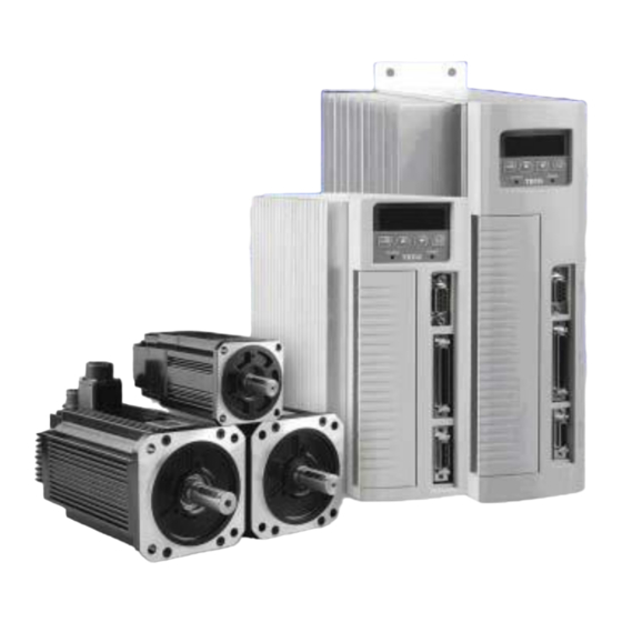
- Page 1 AC Servo System TSTA series Install Operate Manual...
- Page 3 ■ Warning and Caution: Warning Do not proceed to the assembly of the line while electrifying. circuit & change components between entering shutting down the power supply and stopping showing CHARGE LED light of the Servo driver. The output of Servo driver [ U, V, W ] must not touch the AC power. Caution ...
- Page 4 Read this covering letter detail before using Servo driver. Fist of all, thank you for using TECO Servo Driver TSTA Series (“TSTA” for short) and Servo Motors. TSTA can be controlled by digital board or PC, and provide excellent performance for a wide range of applications and different requirement from customers.
-
Page 5: Table Of Contents
1-1-1 Check the Model of Servo Drive............... 1-1 1- 1-2 Check the Model of Servo Motor ............. 1-2 1-1-3 Synopsis of Servo Drives and Motors............. 1-2 1-2 Parts Description of Servo Drive..............1-3 1-3 Control Modes of Servo Drive................. 1-4 1-4 Installation and Storage of Servo Drive ............ - Page 6 Wiring Picture of Position Control (Pi Mode)..........2-3-4 Wiring Picture of Speed Control (S Mode)........... 2-3-5 Wiring Picture of Torque Control..............Chapter 3 Description of the Faceplate Control 3-1 Description of Driver-Faceplate................3-2 Description of Signal-Display of Faceplate............3-2-1 Description of Status-Display Function............
- Page 7 5-3-5 Encoder Output ..................... 5-3-6 Smoothness Adjustment of Speed Command..........5- 3-7 Definition of Speed Turning-Direction............5-3-8 Tone up of Speed Loop.................. 5-3-9 Notch Filter ..................... 5-3-10 Torque Limit of Speed Mode................ 5-3-11 Gain Switching Function................5-3-12 Other Function of Speed Control..............5-4 Position Mode......................
- Page 8 Selection of Outside Reviving Resistor............5-6-8 Setting of Fan Running.................. 5-6-9 Analog Monitor....................5-6-10 Parameter Reset................... Chapter 6 Parameters 6-1 Parameter Groups and Listing................6-1 6-2 Parameters Summary ..................6-2 Chapter 7 Communication Function 7-1 Communication Function (RS232)............... 7-1- 1 Communication Wiring .................. 7-1-2 Communication Protocol and Form ............
-
Page 9: Check The Model Of Servo Drive
There must be the “QC”-seal in each servo drive, if not, please do not proceed Power ON. If there is any bug or irregular under the situation above, please contact TECO’s Local sales representative or distributor instantly. 1-1-1 Check the Model of Servo Drive... -
Page 10: Check The Model Of Servo Motor
1-1-2 Check the Model of SERVO Motor TS series: TS B 08 751 C 2 N H 3 1 0 1... -
Page 11: Synopsis Of Servo Drives And Motors
CB、 CC、 MB series: – 2 D E 7 7 CB 30 Encoder : Motor ratio power : CB series : 6 : Standard Frame : : 12 : 120 W AC input voltage (15 lines) CB series : 1 :... -
Page 12: Parts Description Of Servo Drive
TSC06201 TSC06401 — — — TST06201 TST06401 6CC201 6CC401 1-2 Parts Description of Servo Drive... -
Page 13: Control Modes Of Servo Drive
TSTA15 / TSTA20 TSTA30 TSTA50 / TSTA75 Keypad 1-3 Control Modes of Servo Drive There are many kinds of control-mode. The detail modes display as fellow:... -
Page 14: Installation And Storage Of Servo Drive
Name Code Explanation Position Mode Position control for the servo motor is achieved via (External Pulse an external pulse command. Position command is entered at CN1. Command) Position Mode Position control for the servo motor is achieved via by 16 commands stored within the servo controller. (Internal Pulse Execution of the 16 positions is via Digital Input signals. - Page 15 Ambient Temperature: 0 ~ + 55 ℃; Ambient Humidity: Under 85% RH (Under the condition of no frost). Stored Temperature: - 20 ~ + 85 ℃; Stored Humidity: Under 85%RH (Under the condition of no frost). Vibrating: Under 0.5 G. ...
- Page 16 1-4-2 Mounting Direction and Space Requirements...
-
Page 17: Installation
1-5 Installation and Storage of Servo Motor Ambient Temperature: 0 ~ + 40 ℃; 1-5-1 Installation and Storage Conditions Ambient humidity: Under 90% RH (No Frost). Storage Temperature: - 20 ~ + 60 ℃; Storage temperature: Under 90%RH (No Frost). Vibration: Under 2.5 G. In a well- ventilated and low humidity and dust location. - Page 18 2. The cable need to keep dry. 3. Please fixing the wiring cable certainly, to avoid the cable ablating or breaking. 4. The extending length of the shaft shall be enough, if not, there will be the vibration from motor operating. Wrong Example Correct Example 5, Please do not beat the motor when installing or taking it apart.
-
Page 19: Chapter 2 System Configuration And Wiring
Chapter 2 System Configuration and Wiring 2-1 Configuration and Wiring 2-1-1 General Wiring Diagram 2-1-2 Wiring Description for Servo Drive The wire material must go by “Wiring Specifications.” Wiring Length: Command Input Wire: Less than 3m. -
Page 20: Specifications
Encoder Input Wire: Less than 20m. The Wiring goes by the shortest length. Please wire according to the standard wiring schema. Don’t connect if no using. Motor output terminal (U、 V、 W) must be connected correctly. Otherwise the servo motor will abnormally function. - Page 21 Motor 2.0mm ² 2.0mm ² 2.0mm ² 2.0mm ² 3.5mm ² U、 V、 W Connection A.W.G.14 A.W.G.14 A.W.G.14 A.W.G.14 A.W.G.12 Control Power 1.25mm² 1.25mm² 1.25mm² 1.25mm² 1.25mm² r、 s Input A.W.G.16 A.W.G.16 A.W.G.16 A.W.G.16 A.W.G.16 2.0mm ² 2.0mm ² 2.0mm ² 2.0mm ²...
- Page 22 4. RS232 -> 9 Pins D-type Joint.
- Page 23 2-1-4 Motor Terminal Wiring A Table of Motor-Terminal Wiring (1) General Joint: Terminal Symbol Color Signal White Black Green Fine red DC +24V Brake control wire Fine yellow (2)Military Specifications Joint(No Brake): Terminal Color Signal White Black Green (3)Military Specifications Joint(Brake): Terminal Color Signal...
- Page 24 Fine BK control yellow wire P.S.: The military joint with BK of servo motor has 9 Pins; and the encoder joint has also 9 Pins. Please confirm before wiring. 2-1-5 Standard Diagram of Motor and Power * The Wiring Example of Single Phase Main Power (Less than 1KW) * The Wiring Example of 3 Phase Main Power (More than 1KW)
- Page 25 2-1-6 TB Terminal Terminal Name Detail Sign Control-loop power Connecting to external AC Power. input terminal Single Phase 200~230VAC +10 ~ -15% 50/60Hz ±5% Connecting to external AC Power. Main-loop power input terminal Single / 3 Phase 200~230VAC +10 ~ -15% 50/60Hz ±5% External Please refer to Cn012 to see resistance value, when using regeneration...
- Page 26 Regeneration *If no using external regeneration resistance, PC-P1 need be close, P doesn’t be connected. terminal common *When using external regeneration, add regeneration resistance between PC-P, P1 doesn’t be wired. point Internal regeneration resistance terminal Motor terminal wire is red Motor-power output Motor terminal wire is white terminal...
- Page 27 2-2 I/O Signal Terminal There are 3 groups of I/O terminal, which contain RS232 communication terminal, CN1 control signal terminal and CN2 encoder terminal. The diagram below displays all positions for the terminal. 2-2-1 CN1 Signal Terminal (1) Diagram of CN1 Terminal:...
- Page 28 P.S.: 1. If there is unused terminal, please do not connect it or let it be the relay terminal. 2. The Shielded Wire of I/O signal should connect to the case of connector. (2) CN1 Signal Name and Explanation: (a) General I/O Signal: Signal Function Symbol Pin No.
- Page 29 Position Pulse Pulse Encoder A-Phase Output PA Command Input Encoder Output / /Pulse A Phase Position Symbol Sign Encoder B-Phase Output PB Command Input Encoder Output 38 /Sign 17 /B-Phase /PB Open Collector Encoder Z-Phase Output 2-11...
- Page 30 Position Encoder /Z-Phase Output 40 Command PW 2-12...
- Page 31 Input. Speed / Torque Analog Signal Ground Terminal 29,32,4 +15V Analog Command +15Terminal V PW Output Input Torque Control Speed Limit -15V PW Output Command / CCW Terminal -15V Torque Command Limit CW Torque DI PW Conmen Terminal DICOM 47 Command Limit Analog Monitor +24V PW Output...
- Page 32 In Speed Mode, when, external speed command is 5-3-1 operated at SPD1=0, SPD2=0, input the voltage Speed Analog 5-3-2 5- range: -10V~+10V, Sn216 can be set input command Input 3-3 5-3- voltage: ±10V’s Motor output speed. Torque Analog In Torque Mode, input the voltage range -10~+10V, Tn103 can be set input voltage ±10V’s motor Command 5-2-15-...
- Page 33 Analog Signal Analog signal grounding: CN1 - > Pin ― Ground 26、 27、 28、 30、 31、 33、 34. Terminal +15V PW Output +15V ALL To provide ±15V output power (Max. 10mA), which ― Terminal can be used in servo drive – external voltage command.
- Page 34 Internal speed command / PI/P Switch DI-3 PCNT DI-10 SPD1 Limit select Internal speed command / Operation DI-4 CCWL DI-11 SPD2 Limit select Limit Control Operation Mode DI-5 DI-12 Limit Switch Reverse Direction External DI-6 TLMT DI-13 SPDINV Speed Torque Limit Command Pulse error amount...
- Page 35 Digital Input Function (Except CCWL and CWL are high electric potential, other terminal layout are low electric potential. Please refer to 5-6-1 to see related parameters) Function Chap Signal Name Mode I/O Function Sign Servo On ALL SON and IG24 close loop: Servo ON ; SON and IG24 5-6-3 5-6-4 open loop: Servo OFF.
- Page 36 Internal speed SPD1 Internal speed setting and limit: 5-2- command / SPD2 Speed Speed Limit 5-3- limit select 1 Command Command Internal speed (Speed Mode) (Torque Mode) command / External External limit select 2 limit(PIC) command(SIN) Sn201 Tn105 Sn202 Tn106 Sn203 Tn107 “1”: Close loop with IG24...
- Page 37 Digital Input Function Explanation (Except CCWL and CWL are the high electric potential, other terminal layout are the low electric potential, please refer to 5-6-1 to check related parameters setting) Function Signal Name Symbol Mode I/O Function Chapter Control Mode Pe/S/T When MDC and IG24 close loop, current control Switch mode will transform into default control mode,...
- Page 38 (Except CCWL and CWL are the high electric potential, other terminal layout are the low electric potential, please refer to 5-6-1 to check related parameters setting) Function Signal Name Symbol Mode I/O Function Chapter Internal POS1 Internal position command select explanation: 5-4-2 Position POS2...
- Page 39 Alarm ALL If normally operates, the terminal layouts ALM and IG24 open loop. When alarm occurs, ― protection-function operates, the terminal and IG24 close loop. Zero Speed When the motor speed is less than the speed from Sn215, the terminal layout ZS and IG24 5-3-12 close loop.
- Page 40 (3) CN1 Interface Circuit and Wire Mode: The diagram below introduces all interface circuit of CN1 and wire-method of host controller. (a) Digital input interface circuit (IO1): Digital input interface circuit can be operated by relay or collector transistor circuit. The relay should be the low electric current, in order to avoid the faulty contacting.
- Page 41 2-23...
- Page 42 (b) Pulse Command Input Interface Circuit(IO3): Suggesting to use the input method of Line Driver to send the pulse command. The maximum input command frequency is 500kpps. Using the input method of Open Collector will cause the decrease of input command frequency, the maximum input command frequency is 200kpps.
- Page 43 (Line Driver) (Open Collector) The max pulse command by differential input Maximum input command frequency of open line driver frequency is 500kpps collector is 200kpps Open Collector – Selection of Resistance Open Collector (Internal 24V) Example Servo Driver DC24V IP24 CN1-45 CN1-41 2 K Ω...
- Page 44 (d) Analog Input Interface Circuit(IO5): There is sometimes ripple inside the server internal power. Adverse external power polarity will cause server damage. Maximum external power voltage (Vc) should be less than12V; terminal input voltage should not more than10V. Over voltage will cause damage.
- Page 45 Analog Input Interface Circuit Servo Driver 2-27...
- Page 46 2-2-2 CN2 Encoder Signal Terminal Explanation (1) Diagram of CN2 Terminal: (a) Diagram of Fewer Wiring Type Encoder: (b) Diagram of non-Fewer Wiring Type Encoder: P.S.: Do not wire to the terminal, which is un-operated. (2) Name and Explanation of I/O Signal: 2-28...
- Page 47 Encoder Output No. and Color Milit Functi- General Joint Joina-ry n Signal Name Terminal Layout Function 9 wires wires (fewer (non-fe put wiring) wer No. wiring) Power output + Terminal +5V white Red B 5driver). When the cable is more than V Power for encoder(provided from 2 2-29...
- Page 48 20m, user should separately use 2 2-30...
-
Page 49: Motor Terminal
cables to avoid decreasing voltage of 3 Power output - Terminal Black Black I encoder. When the cable is more than 30m, please contact the 4 distributorship. A Phase Green Green Encoder A Phase: From motor terminal encoder input Blue Green White C to the driver. - Page 50 2-3 Standard Wiring Diagram of Control Signal 2-3-1 Position Control (Pe Mode) Wiring Diagram(Line Driver) 2-32...
- Page 51 2-3-2 Position Control (Pe Mode) Wiring Diagram(Open Collector) 2-33...
- Page 52 2-3-3 Position Control (Pi Mode)Wiring Diagram 2-34...
- Page 53 2-3-4 Speed Control(S Mode)Wire Diagram 2-35...
- Page 54 2-3-5 Torque Control (T Mode)Wire Diagram 2-36...
- Page 55 Chapter 3 Functions on Panel Operator 3-1 Functions on Driver Panel Operator This device includes 5 digits 7 segment LED display, 4 control keys and 2 LED lights as below. When the POWER-LIGHT(green) shines, it means this equiptment is power on then it can normally operate;...
- Page 56 To enter Torque parameter after pressing MODE-Key once. To enter Speed parameter after pressing MODE-Key once. To enter Position parameter after pressing MODE-Key once. To enter Quick parameter after pressing MODE-Key once. To enter Hyper-Function parameter after pressing MODE-Key once. To enter User-Control parameter again after pressing MODE-Key once, and so on.
- Page 57 Refer to front example: If there is no any setting, press MODE-Key once to return back to parameter-selection. There are some hexadecimal displayed parameters. Some of parameters in this equipment is displayed by hexadecimal. If the hightest digit shows H, it stands for that the parameter is set by hexadecimal.
- Page 58 Discription of Positive/Negative Display Display of Positive Display of Negative 3000 -3000 If the setting number range is equal or less than 4 digits and displayed in Negative, the highest digit will display the minus sign. Ex: Sn201(Internal Speed Command 1). 30000 -30000 If the setting number range is more than 4 digits and displayed in Negative,...
- Page 59 User can use panel board at this equipment to clean Alarm without using input terminal ALRS. Here below is the operat-discription: Step Description Control Key LED Display after Opertion Alarm If voltage over low alarm, AL-01 shines. After alarm is cleared, remove input contact point SON operation. (= remove servo on) Then press UP-Key and DOWN-Key at the same time.
- Page 60 Un-01 Actual motor speed Ex: 120 is displayed. It means current motor speed is 120 rpm. It is displayed in accordance with ratio torque percentage. Ex: 20 is displayed. It means current motor torque output is 20% of ratio Un-02 Actual motor torque torque.
- Page 61 When Cn002.2=0(no use auto gain adjust function), it displays current default load inertia ratio in Cn025. Un-19 Load inertia x0.1 When Cn002.2=1(keep using auto gain adjustfunction), it displays current forecasting load inertia ratio.
- Page 62 3-2-2 Diagnosis Functions User can use diagnosis parameter to get all informations of current system. There are the description below: Parameter Name and Function Signal dn-01 Current control mode dn-02 Output connect terminal signal dn-03 Input connect terminal signal Software version dn-04 dn-05 JOG mode operation...
- Page 63 Position control(internal position command) - Pi dn-02 (Output terminal signal) User can use dn-02 to get the situation of current output terminal signal. Here below is the description of the penal borad: When output terminal signal is low electric potential (close loop with IG24), the corresponding LED will shine;...
- Page 64 dn-03 (Input terminal signal) User can use dn-03 to know the situation of current input terminal signal. Here below is the panel board description: When output terminal signal is low electric potential (close loop with IG24), the corresponding LED will shine; when output terminal signal is high electric potential (open loop with IG24), the corresponding LED will not shine.
- Page 65 dn-05 (JOG Operation) User can use dn-05 to turn on JOG J, here is the description below: Attention: The JOG is operated in accordance with Sn201(internal speed command 1). Please set Sn201 before executing this function. Attention: The motor will power on immediately when entering JOG mode, no matter the motor use input terminal SON or not. dn-07 (External Voltage command bias automatic adjusting) When external torque or speed analog command is 0V, the motor might rotate slowly.
- Page 66 dn-08 (Servo Series) User can use dn-08 to check the current combination of drives and motor, which is showed as below. If the displayed setting value is different from actual combination, please contact to lock distributors. 3-12...
- Page 67 Motor Standards dn-08 Display Encoder Drives Model Motor Model Watt Speed Standards Cn030 Setting (rpm) JSMA-LC03AB 2500 3000 JSMA-LC03AH 8192 JSMA-SC02AB 2500 JSDA-15 3000 JSMA-SC02AH 8192 JSMA-SC04AB 2500 3000 JSMA-SC04AH 8192 JSMA-LC08AB 2500 3000 JSMA-LC08AH 8192 JSMA-SC04AB 2500 3000 JSMA-SC04AH 8192 JSMA-SC08AB 2500...
- Page 68 JSMA-MB10AB 2500 1000 2000 JSMA-MB10AH 8192 JSMA-MH10AB 2500 1000 1500 JSMA-MH10AH 8192 JSMA-MA15AB 2500 1500 1000 JSMA-MA15AH 8192 Motor Standards dn-08 Display Encoder Drives Model Motor Model Watt Speed Standards Cn030 Setting (rpm) JSMA-MB15AB 2500 1500 2000 JSMA-MB15AH 8192 JSDA-30 JSMA-MC15AB 2500 1500...
- Page 69 JSMA-MB30AH 8192 JSMA-MC30AB 2500 3000 3000 JSMA-MC30AH 8192 3-15...
- Page 71 Chapter 4 Operation of Trial Run Before executing trial run, please confirm all wiring work have been accomplished. The description below is the trial run operation and purpose; and when trial run and host controller operate together, it descripts in accordance with speed control loop (analog voltage command) and position control loop (external pulse command).
- Page 72 4-1 Non-loaded Servo Motor Trial Run In the process of trial run, user must take the servo motor from the mechanical system apart. Ex.: Coupling or belt etc.. In order to prevent the damage of mechanical system in the process of trial run, the servo motor must execut trial run in non-loaded situation.
- Page 73 After the setting is complete, please reset the power. If there is still other abnormal alarm, itmeans the drives can not operate normally. (User need refer to 8-2(abnormal clear). After the abnormal is cleared, operat the drives again. If the abnormal alarm still can not cleared again, please contact to local distributors to get the information and help.
- Page 74 Attention: The JOG is operated in accordance with Sn201(internal speed command 1), so user need to set Sn201 before operating this function. Attention: Regardless of using SON to servo on. After entering JOG mode, motor will servo on immediately. 4-2 Non-loaded Servo Motor Trial Run with Host Controller During this step, user can make sure the control signal wires and the control signal electric potential between servo drives and host controller are correct or not.
- Page 75 a. No command signal input: In speed control mode, input 0V to speed analog input terminal. In position control mode, please connect the external pulse command terminal “Pulse” to”/Pulse”, and “Sign” to “/Sign” Turn the Servo ON Signal on: Connect the SON to low electric potential to turn on servo motor and check if there is any abnormal alarm.
- Page 76 3. Check the relationship between motor speed and speed analog command input: Increase the speed analog command voltage by degrees. Check the motor actual speed in Un0-01 and make sure analog speed command ratio(Sn216) and analog speed command limit(Sn218) are correct or not.
- Page 77 2. Setting of electric gear ratio: Please set the necessary position control parameter electric gear ratio Pn302~Pn306(refere to 5-4-3) in accordance with the standard of servo motor encoder and motion table application. 3. Turn on Servo Motor: Connecting the SON to the low electric potential to turn on servo motor. 4.
- Page 78 Please set the related parameters of servo dirve in accordance with the necessary of host controller and mechanical system. Confirm if the servo motr rotating direction and speed setting is in accord with the necessary of mechanical system. 1.
- Page 79 Chapter 5 Control Function 5-1 Selection of control mode There are torque, speed and position mode in this device. Users can operate single mode, or canuse multi mode to switch control mode. The diagram below is the description of parameter. Parameter Control Signal...
- Page 80 The method of torque command input of this device: Using one group of analog voltage to control motor torque. The diagram below is the wiring: Attention! User need to confirm the relationship between SIN(analog torque command input) and input contacts RS1, RS2(torque command CW/CCW selection). Refer to Chapter 5-2-4.
- Page 81 5-2-2 Analog torque command bias adjusting Even the torque command is 0V, motor could also posibly rotate slowly. The main reason is that external analog voltage has a few bias value. Under this situation, user can directly adjust Tn104 to adjust the bias value or use auto-adjusting.
- Page 82 Parameter Control Name Setting Description Signal mode ★Tn101 Torque command No operating torque command linear ac/deceleration ac/deceleration function Operating torque command linear ac/deceleration function The Definition of torque command linear ac/deceleration constant means The Time in which the torque command arises from “0”...
- Page 83 (3) Input contact TRQINV(torque command inverse) Attention! 3 methods can operate at the same time. User need to make sure the final motor direction definition in order to avoid erro. Input Contact Control Descrpition mode No torque Rotating in current torque command direction Rotating in current torque command inverse direction No torque P.S.: Input contacts status 1 means on;...
- Page 84 Parameter Control Name Default Unit Setting range Signal mode CCW Torque command limit Cn010 0~300 value Torque command limit Cn011 -100 -300~0 value 5-2-6 Speed limit of torque mode In torque control, user can use input contacts SPD1 and SPD2 switching the 2 methods to operate the motor speed limit.
- Page 85 The diagram below is the internal 3-stages speed limit setting. The setting value means motor CCW and CW speed limit value. Parameter Name Default Unit Setting range Control mode Signal Tn105 Internal speed limit 1 0~3000 Tn106 Internal speed limit 2 0~3000 Tn107 Internal speed limit 3...
- Page 86 5-2-7 Other torque control functions Torque Achieving Function When the torque of CW or CCW is more than the speed in Tn108 (torque achieving judging value), the output contact INT operates. Here is the description: Parameter Name Default Unit Setting range Control mode Signal Torque achieving...
- Page 87 Speed Command Handling Speed Controllor 5-3-1 Speed Command Selecting There are 2 kinds of input command method. Using input contacts - SPD1、 SPD2 – to switch the 2 methods below to operate speed command: (1) Internal speed command: Internal default 3-stages speed command. (2) External analog command: Using 1 analog voltage command signal ...
- Page 88 Internal speed command 1 Sn201 Internal speed command 2 Sn202 Internal speed command 3 Sn203 P.S.: Input contacts status 1 means on; 0 means off. Please check 5-6-1 to set high electric potential or low electric potential. The diagram below is about external analog speed command wiring: And here is the internal 3 stages spped command setting: Parameter Name...
- Page 89 it matches up 1000rpm speed command. 5-3-3 Analog Speed Command Bias Adjusting Even the analog speed command is 0V, motor could possibly rotate slowly. The main reason is external analog voltage has few bias. User can use Sn217 to adjust bias value or automatic adjusting under this situation. (Please refer 3-2-2).
- Page 90 Parameter Name Default Unit Setting range Control mode signal Analog speed Sn218 3050 100~4500 command limit 5-3-5 Encoder Signal – Encode Output The encoder signal of motor can be encoded handled through this device then outputing to host control to become to position control loop.
- Page 91 Encoder output Z Phase signal CN1-39 Encoder output /Z Phase signal CN1-40 時 間 時 間 5-3-6 Speed Command Smoothly When there are overshooting or vibration of motor after entering command, user can execute the 3 kinds of speed command smooth control in this drive and decide to execute which smooth control in accordance with which necessary. If user executes one of them, please set Sn205 first to turn on all functions.
- Page 92 Sn205 No using speed command ac/deceleration function Speed command To use speed command once smooth ac/deceleration ac/deceleratio function n method To use speed command linear ac/deceleration function To use S-curve speed command ac/deceleration function Here is the description of 3 kinds of speed command smooth control. Speed command once smooth ac/deceleration: User must set Sn205=1 to turn on speed command once smooth ac/deceleration function before using this function.
- Page 93 Speed command linear ac/deceleration function: User must set Sn205=2 to turn on speed command linear ac/deceleration function before using this function. Parameter Name Default Unit Setting range Control mode Signal Speed command linear ac/deceleration Sn207 msec 1~50000 constant The definition of Speed command linear ac/deceleration Constant means the time in which the speed increases (linear) from zero to the ratio speed.
- Page 94 Speed command linear Sn207 msec 1~50000 ac/deceleration constant S-Curve speed command ac/deceleration time Sn208 msec 1~1000 setting S-Curve speed command Sn209 msec 0~10000 acceleration time setting S-Curve speed command Sn210 msec 0~10000 deceleration time setting Ac/deceleration Because of strong change of ac/deceleration when on or off, which will cause vibration of mechanical system.
- Page 95 Motor rotating (CCW) (CCW) direction definition (motor load terminal) (CW) (CCW) (CCW) (CW) (CW) (CW) Input contact SPDINV Description Control mode Rotating with current speed command direction Rotating with current speed command inverse direction P.S.: Input contacts status 1 means on; 0 means off. Please check 5-6-1 to set high electric potential or low electric potential 5-3-8 Speed Loop Gain The diagram below is the related parameters of speed control loop.
- Page 96 5-3-9 Notch Filter When the low machine rigidity, the bearing twisting or other vibration situation causing vibration or noise (the mechanical system can not increase controller gain), this device provides Notch Filter to clear this phenomenon. Inputing vibrating frequency in Cn013(Notch Filter frequency) and matching up Cn014 () to adjust the frequency range.
- Page 97 5-19...
- Page 98 5-3-10 Torque Limit in Speed Mode In speed mode, the motor torque limit is achieved by input contact TLMT switching the 2 methods below: (1) Inter toque limit: Using internal default Cn010(CCW Torque command limit value) and Cn011(CW Torque command limit value). (2) External analog command: Using 2 groups of analog voltage command signals to enter PIC(CN1-27) separately to limit CCW torque and NIC(CN1-28) to CCW torque.
- Page 99 5-3-11 Gain Switch Function The gain switch function in this device contains speed loop gain PI/P switching and 2-stage gain switching. The applications are: (1) In speed control, to restrain ac/deceleration overshooting. (2) In position control, to restrain the breadth of vibration and decrease the adjusting time. (3) To decrease the noise from using Servo Lock function.
- Page 100 When torque command is less than Cn016 switching condition: Controlled by PI; When torque command is more than Cn016 switching condition: switching to : Controlled by P only. Here is the diagram below: (2) Estimating speed command to switch PI/P-mode When speed command is less than Cn017 switching condition: Controlled by PI;...
- Page 101 (4) Estimating position error value to switch PI/P-mode When position error value is less than Cn019 switching condition: Controlled by PI; When position error value is more than Cn019 switching condition: Controlled by P only. Here below is the diagram: Using input contact PCNT to switch PI/P-mode When input contact PCNT doesn’t operate: Controlled by PI;...
- Page 102 P.S.: Input contacts status 1 means on; 0 means off. Please check 5-6-1 to set high electric potential or low electric potential. 2 Stages Gain Switching Mode Select Cn015.1 (estimating-type selection of 2 stages gain mode) and set the switching conditions of 2 stages gain mode at related parameter, before using 2 stages gain switching mode.
- Page 103 Switching condition of 2 stages gain mode Cn024 pulse 0~50000 Pi/Pe/S (position error value) P.S.: The 1 gain contains Pn310(position loop gain 1), Sn211(speed loop gain 1) and Sn212(Speed loop integral time constant 1). The 2 gain contains Pn311(position loop gain 2), Sn213(speed loop gain 2) and Sn214(speed loop integral time constant 2). (1) Estimating torque command to switch 2 stages gain mode gain control;...
- Page 104 5-26...
- Page 105 (3) Estimating acceleration command to switch 2 stages gain mode gain control. When acceleration command is less than Cn023 switching condition: Using the 1 gain control When When acceleration command is more than Cn023 switching condition: Switching to the 2 acceleration command is less than Cn023 switching condition again: Switching to the 1 gain control in accordance with Cn020 switching delay time.
- Page 106 (5) Using input contact G-SEL to switch 2 stages gain mode When the input contact G-SEL doesn’t work: Using the 1 gain control; gain control; When the input contact G-SEL works: Switching to the 2 When the input contact G-SEL doesn’t work again: Switching to the 1 gain control in accordance with Cn020 switching delay time.
- Page 107 Zero Speed Function When the speed is less than the speed in Sn215 (Value of ZS), the output contact ZS works: Parameter Control Name Default Unit Setting Range Signal Mode Sn215 Value of zero speed 0~4500 P.S.: Input contacts status 1 means on; 0 means off. Please check 5-6-1 to set high electric potential or low electric potential User can set Sn204 () to “1”.
- Page 108 Servo Lock In speed mode: the Servo Lock is used to lock servo motor when input voltage command is not 0V. When input contact LOK operates: Although this device stays in speed mode, it will change to internal position control mode temporally to make the motor be fixed.
- Page 109 5-4 Position Mode Position Mode is used to high-precision system. Ex: all kinds of machines or machine tools of industry⋯etc. . The Position Mode has 2 kinds of input mode: External pulse command input mode and internal position command mode. External pulse command input mode: Receiving the pulse command from host controller to achieve fixed position function;...
- Page 110 Parameter Control Name Setting Description Signal Mode ★Pn301.0 Position pulse (Pulse)+(Sign) command selection Pulse from (CCW)and (CW) AB-Phase Pulsex2 AB-Phase Pulsex4 ★Pn301.1 Position pulse Positive Logic command logic selection Negative Logic ★The setting will be in effect after returning on the power. There are 2 kinds of interfaces of pulse command: (Open collector) and (Line driver).
- Page 111 LineDrive: t1, t2 ≦ 0.1µs > 3µs τ (CCW)/ ≧ 1.0µs (τ/T) ≦ (CW) Pulse Pulse OpenCollector: Sign t1, t2 ≦ 0.2µs > 3µs τ ≧ 2.0µs (τ/T) ≦ LineDrive: t1, t2 ≦ 0.1µs τ Pulse ≧ 1.0µs (τ/T) ≦ Sign AB-Phase Pulse OpenCollector:...
- Page 112 Pulse Number Pn321 Rotating Number Pn323 Pn325 Pulse Number Pn324 Rotating Number Pn326 Pn328 Pulse Number Pn327 Rotating Number Pn329 Pn331 Pulse Number Pn330 Rotating Number Pn332 Pn334 Pulse Number Pn333 Rotating Number Pn335 Pn337 Pulse Number Pn336 Rotating Number Pn338 Pn340 Pulse Number...
- Page 113 Rotating Number Pn353 Pn355 Pulse Number Pn354 Rotating Number Pn356 Pn358 Pulse Number Pn357 Rotating Number Pn359 Pn361 Pulse Number Pn360 Rotating Number Pn362 Pn364 Pn363 Pulse Number There are absolute and relative types – internal position command mode in accordance with Pn316. Here is the setting: Parameter Control...
- Page 114 P.S.: Input contacts status 1 means on; 0 means off. Please check 5-6-1 to set high electric potential or low electric potential If user would like turn off the motor rotation during the position movement To trigger the input contact PHOLD and the motor will decelerat and stop. When the input contact PTRG is triggered again ...
- Page 115 P.S.: Input contacts status 1 means on; 0 means off. Please check 5-6-1 to set high electric potential or low electric potential If user ignores this position command and stop the motor during position movement, user can trigger input contacts CLR (Pn315 must be set 1 or 2, please refer to 5-4-7), motor will stop immediately.
- Page 116 P.S.: Input contacts status 1 means on; 0 means off. Please check 5-6-1 to set high electric potential or low electric potential 5-4-3 Electronic Gear Ratio User can use Electronic Gear Ratio to definite the inputted Unit Pulse Command to make the transmission to move to any distance.
- Page 117 Set the Electronic Gear Ratio(Assume: Definiting 1 1. 1 Rotating of Ballscrew The Motion Table will Pulse Command = moving 1um, the setting method of move 5mm. Electronic Gear Ratio is contained in the next chapter) 2. If the Motion Table need move 10mm, the 1.
- Page 118 ElectronicGearRatio = LoadMoving1DisRotatingPutanceOfLoadShlseValueaft×4_1Rotating ÷ 1PulseCommandMovingDistance If the deceleration ratio between motor and load shaft is (m means Motor Rotating Value, n means Load Shaft Rotating Value), and the formula for Electronic Gear Ratio is: ElectronicGearRatio = MovingDisPulseValuetanceOfMotionOf1RotatingFoTableForrMotorEnco1RotatingOfderLoadShaft×4 ÷ × mn MovingDistanceOf1PulseCommand 4.
- Page 119 Input Contact Input Contact Numerator of Electronic Gear Ratio Control Mode Numerator of Electronic Gear Ratio 1 Pn302 Numerator of Electronic Gear Ratio 2 Pn303 Pi/Pe Numerator of Electronic Gear Ratio 3 Pn304 Numerator of Electronic Gear Ratio 4 Pn305 P.S.: Input contacts status 1 means on;...
- Page 120 Transmission System Setting Process Ball Screw Understanding whole system specifications: Load Shaft(Ball Screw)moving distance of 1 rotating=5mm Pulse Value/1 rotating of Motor Encoder =2000pulse Definiting the moving distance of 1 Pulse Command Moving Distance of 1 Pulse Command=1um 3. Counting the Electronic Gear Ratio: 4.
- Page 121 Transmission System Setting Process Transmission Belt Understanding whole specifications: Deceleration Ratio=1/8 Load Shaft(Idler) MovingValue of 1Rotating = 3.14×100mm = 314mm PulseValue of 1Rotating for Encoder =8192pulse Definiting the moving distance of 1 Pulse Command: Distance for 1Pulse Command =10um 3. Counting the Electronic Gear Ratio: 4.
- Page 122 Setting Example: (1) If achieving 95% of Position Pulse Command Frequency Output in 30msec: Pn313 = =10(msec) (2) If achieving 75% of Position Pulse Command Frequency Output in 30msec: Pn313 = = 22(msec) 5-4-5 Definition of Position Command Direction In position mode, user can use Pn314 (Position Command Direction Definition) to definite motor rotating direction. The setting is showed as follow: Parameter Control...
- Page 123 5-4-6 Adjusting of Position Loop Gain The table below is about the parameter of position control loop. This device provides 2 groups of position controller. User can use gain switching function to change it. (Please refer to 5-3-11) Parameter Control Name Default Unit...
- Page 124 When CLR is turned on: canceling the position command to stop motor rotating and clearing the pulse incorrect value. P.S.: Please refer to 5-6-1 to set high or low electric potential at input contact. 5-4-8 Home Description of Home Mode When using the function “HOME”, user can use input contacts ORG, CCWL, or CWL to be reference HOME;...
- Page 125 After Home is turned on, motor will search Home in 1 stege speed CCW and find the closest Z Phase Home without Referenct Home. When using this function, Pn365.1=2 must be set. (After finding Z Phase to be the Home, it stops in accordance with Pn365.3 setting).
- Page 126 Pn365.0 Pn365.1 means HOME operates normaly; means there is no HOME operation Other Setting of HOME The Speed of HOME is descripted as follow: Parameter Name Default Unit Setting Range Control Mode Signal Pn366 stage-high speed of HOME 0~2000 Pi/Pe Pn367 stage-low speed of HOME 0~500...
- Page 127 P.S.: Input contacts status 1 means on; 0 means off. Please check 5-6-1 to set high electric potential or low electric potential Speed/Position Timing Charts for HOME The table list below is about the speed/position timing charts of HOME for different Pn365 setting: Pn365.0 Pn365.1 means no operating HOME function...
- Page 128 Pn365.0=2(After turning on HOME, CW in 1 stage speed to find Reference HOME: ORG) Pn365.1=1(After finding Reference HOME, continue going ahead in 2 stage speed to find the closest Z Phase to be the HOME) Pn365.2=2(Input Contact SHOME turning on HOME) Pn365.3=0(Returning to the HOME) 5-50...
- Page 129 (After turning on HOME, CCW in 1 Pn365.0=3 stage speed to find the Reference HOME: ORG) Pn365.1=1(After finding Reference HOME, continue going ahead in 2 stage speed to find the closest Z Phase pulse to be the HOME) Pn365.2=2(Input Contact SHOME turning on HOME) Pn365.3=0(Returning to the HOME) Pn365.0=2(After turning on HOME, CW in 1 stage speed to find the Reference HOME: ORG)
- Page 130 (After turning on HOME, CCW in 1 Pn365.0=3 stage speed to find the Reference HOME: ORG) Pn365.1=2(Finding the Reference HOME: the Rising Edge of ORG to be the HOME) Pn365.2=2(Input Contact SHOME turning on HOME) Pn365.3=0(Returning to the HOME ) Pn365.0=4(After turning on HOME, CW in 1 stage speed to find the closest HOME of Z Phase pulse) Pn365.1=2(Finding Z Phase pulse to be the HOME)
- Page 131 (After turning on HOME, CCW in 1 Pn365.0=5 stage speed to find the closest HOME of Z Phase pulse) Pn365.1=2(Finding the Z Phase pulse the be the HOME) Pn365.2=2(Input Contact SHOME turning on HOME) Pn365.3=0(Returning to the HOME) 5-53...
- Page 132 5-4-9 Other Position Control Function PositionComplete Function When the position incorrect value is less than the pulse value which is set in Pn307 (Position Complete value), INP will work. Here is the Explanation: Parameter Control Name Default Unit Setting Range Signal Mode Position Complete...
- Page 133 Theoretically, the bandwidth of inside control loop must be higher than the bandwidth of outside. Otherwise, whole control system will astaticism, then it will cause vibration or abnormally response. The relation of these 3 control loop bandwidths will be showed as follow: Current Control Loop Bandwidth (Inside)>Speed Control Loop Bandwidth (Middle Side)>Position Control Loop Bandwidth (Outside) Because the default current control circuit bandwidth has been already the best situation, the user...
- Page 134 If Cn025(Load Inertia Ratio) is correctly set: Speed Loop Bandwidth = Sn211 (Speed Loop Gain1 ) or Sn213 (Speed Loop Gain2). Speed Loop Integration Time Constant Adding integral items in Speed Control Loop can delete the error of stabilizing Speed and respons fine speed changing quickly.
- Page 135 Gain Adjusting Quick-Parameter There are Gain Adjusting Quick-Parameter in this device. The related Gain Adjustin parameters are in the Quick-Parameter folder. Which gives users convenience of adjusting when Gain Adjusted by hand. When user change the parameter value, the value will be saved immediately and in effect right away without pressing Enter-Key.
- Page 136 Sn211 Speed Loop Gain 1 Integral Time Constant 1 of Speed Sn212 Loop Sn213 Speed Loop Gain 2 Integral Time Constant 2 of Speed Sn214 Loop Pn310 Position Loop Gain 1 Pn311 Position Loop Gain 2 Pn312 Position Loop Feed-Forward Gain When user set 1 in Cn002.2, it means continuing to use Autotuning.
- Page 137 Integral Time Rigidity Position Loop Speed Loop Constant of Speed Mechanical Setting Gain Gain Application Loop Rigidity Cn026 Pn310 [1/s] Sn211 [Hz] Sn212 [x0.2msec] machines drived Synchronous Belt, Chain or Gear: Man-size Moving Table, Middle Transit Belt. The machines drived by Ballscrew though decelerator: Ordinary machines, Mechanics High...
- Page 138 P.S.: After operate Autotuning (Cn002.2=1): if no set 0 in Cn002.2, it will not record the present measured Load Inertia Ratio when cutting power When the Autotuning is operated next time again, servo will use the early setting Load Inertia Ratio in Cn025 starting to measure. 5-5-2 Manul Gain Adjusting Manul Gain Adjusting for Speed Mode Step 1: Please refer to 5-5-1(Autotuning) to set Rigidity Level then get the correct Load Inertia Ratio.
- Page 139 Step 2: If servo system combines with Host Controllor to become the Position Control, set the Position Loop Gain of Host Controllor to related low value. Step 3: Manul adjusting Sn211(Speed Loop Gain1): Setting the value in Sn212 (Integral Time Constant 1 of Speed Loop) higher than the value which is set after Autotuning...
- Page 140 Gain Switch The Gain Switch of this servo contains Speed Loop Gain PI/P Switching and 2-stage Gain Switching. Here is the Applications below: (1) Restraining the overshooting of ac/deceleration in speed control. (2) Restraining the vibration range result from In Position and shortening settling time in position control. Please refer to 5-3-11 (3) Decreasing the noise result from Servo Lock Position Loop Feed-Forward Gain...
- Page 141 Emergency Stop SPD1 Speed 1 Speed 2 SPD2 Mode Changing Inhibittion of Position Command Speed Inverse SPDINV G-SEL Gain Settle Electronic Gear Ratio Numerator 1 Electronic Gear Ratio Numerator 2 Position Trigger PTRG PHOLD Position Hold Start Home SHOME Reference Origin POS1 Position 1 Position 2...
- Page 142 Parameter Control Name Description Signal Mode ★Hn502 DI-2 Programming ★Hn503 DI-3 Programming ★Hn504 DI-4 Programming ★Hn505 DI-5 Programming ★Hn506 DI-6 Programming ★Hn507 DI-7 Programming Please refer to Hn501 to check the setting ★Hn508 method. DI-8 Programming ★Hn509 DI-9 Programming ★Hn510 DI-10 Programming ★Hn511 DI-11 Programming...
- Page 143 ★Hn516 DO-3 Programming Please refer to Hn514 to check setting method ★Hn517 DO-4 Programming Attention! The functions of DI-1 ~ DI-4 could be repeat, but the contactors electric potential of repeated functions must be the same, otherwise there will be AL-07 (Abnormal alarm of DI/DO programming). 5-6-2 Control Mode Switching User can use Input Contoctor MDC to switch Control Mode set by Cn001.
- Page 144 Disable Disable Disable Enable Enable Disable Enable Enable Attention! When the Drive Inhibit occurs in CCW/CW, the priority of Dynamic Brake in Cn009 should be from Cn008, which means assuming Cn008 setting is 0 or 1 (no Dynamic Brake) and Cn009 1 (with Dynamic Brake), the servo will have Dynamic Brake in the end of process.
- Page 145 Attention! Cn008 (BK Mode) must be set to 1 or 3. When the servo system has vertical loading, please set Cn003 to Positive Number. (1) When the Cn003(Output Time for Mechanical Brake Signal) is Positive Number: When the input contactor SON works, servo will immediately on. After exceeding the timming which is set in Cn003, Output Contactor BI works (Mechanical BK stops);...
- Page 146 Using ±300% of torque limit to decelerate Zero Speed Clamp after stopping. ★The setting will be in effect after returning on the power. Attention! When the Drive Inhibit occurs in CCW/CW, the priority of Dynamic Brake in Cn009 should be from Cn008, which means assuming Cn008 setting is 0 or 1 (no Dynamic Brake) and Cn009 1 (with Dynamic Brake), the servo will have Dynamic Brake in the end of process.
- Page 147 Attention! The consumable Regeneration Power (Average Value) should be the 46% of Ratio Power from Built-in Regeneration Resistor The Regeneration Resistor which is builted-in this device can consume the Regeneration Power from Ac/Deceleration Running or Vertical Loading. But in the application: driving servo motor at the loading terminal, user must install Regeneration Resistor by themselves, otherwise this device can not work normally.
- Page 148 When the Regeneration Resistor absorbs the regeneration power, it will produce the high temperature over 100°C. Please be careful to cool it. Please select the heatproof wire when wiring Regeneration Resistor and confirm nothing is connecting to the Regeneration Resistior. 5-70...
- Page 149 Compute the necessary Watt for External Regeneration Resistor If the Loading of Servo Motor is Horizontal Moving, please use the Table List below to decide if the External Regeneration Resistor is necessary. The table list below is about Allowable Frequencies in Regenerative Mode, which definition is: the no-load speed of motor running from 0 to ratio speed then from from ratio speed to 0.
- Page 150 JSMA-MC30 Please use the formula below to compute the Allowable Frequencies in Regenerative Mode in accordance with actual Loading and running speed of motor. If the motor’s actual running Frequencies is more than the computed Allowable Frequencies, user needs to install the external regeneration resistor.
- Page 151 Compute the Energy which main : The Energy which main capacitance can Check the diagram above capacitance can absorb absorb (J) Compute Energy which : The Energy which Regeneration Regeneration Resistor consumes Resistor consumes (J) : The Power which Regeneration Compute Power which...
- Page 152 Always Stop 5-6-9 Analog Monitor The servo provides 2 Analog Signals to monitor the running situation of motor. Here is the setting below: Parameter Control Name Setting Description Signal Mode Analog Monitor Output 1 Analog Monitor Output 2 Cn006 Selection for Analog Monitor Output MON1 MON2...
- Page 153 Parameter Control Name Default Unit Setting Range Signal Mode Analog Monitor 1 Output Bias Cn027 x40mV -250~250 Adjusting Analog Monitor 2 Output Bias Cn028 x40mV -250~250 Adjusting 5-6-10 Reset for Parameter The servo can turn back to the default value with this function. When setting to 1, the power must be restart: Parameter Control Name...
- Page 155 Chapter 6 Parameter 6-1 Definition There are following 9 groups for parameters: Parameter Definition Un-xx Status Display Parameter dn-xx Diagnosis Parameter AL-xx Alarm Traceback data parameter Cn-xx System Parameter Tn1xx Torque Control Parameter Sn2xx Speed Control Parameter Pn3xx Position Control Parameter qn4xx Quick Setting Parameter Multi-function parameter...
- Page 156 Symbol Explanation Parameter is effective after the servo drive is restarted. ★ Parameter is Effective without “Enter”. ◆ 6-2 Parameter System Parameter Setting Control Parameter Name & Function Default Unit Chap. Range Mode ★Cn001 Control Mode │ Setting Explanation Torque Control Speed Control Position Control (external puls Command) Position / Speed Control Switching...
- Page 157 Setting Control Parameter Name & Function Default Unit Chap. Range Mode Cn003 Mechanical Brakes signal output sequence msec 5-6-5 -2000 │ Time Sequence: 2000 P.S.: Input / output contact status 1 means SWITCH; 0 means SWITCH OFF, please refer to 5-6-1 to set high electric action potential or low electric action potential.
- Page 158 It stands for that the number of puls-signal numbers of a Amount │ rotate of the motor-encoder transforming the Cn005- default puls-signal numbers. Pulse Amount Ex: Motor-Encoder : One Rotate has 2000pulse output. Set Cn005=1000 if gain 1000pulse Ration-output. Pulse Setting Control Parameter...
- Page 159 Setting Explanation │ ServoMotor decelerate then stop through default torque forbid(Cn010、 Cn011). ServoMotor decelerate then stop through default torque forbid (Cn010、 Cn011),and drive dynamic brake (priority to Cn008) ServoMotor decelerate then stop through ±300% Torque forbid decelerate then stop. Setting Control Parameter Name &...
- Page 160 Estimate if position mistake over Cn024 Using Enter Contact PCNT to switch it Cn016 Switch-condition in PI/P Mode(Torque Command) 5-3-11 │ Set the Cn015.0=0 first, when Torque Command under Cn016 switch-condition, controled by PI; when Torque Command over Cn016 switch-condition, controled by P only。...
- Page 161 │ Set the Cn015.1=1 first, when Speed Command is under Cn022 switch-condition, use the first-part 4500 increase-condtrol. When Speed Command is over Cn022 switch-condition, switch to the second part of increase-control. When Speed Command is under Cn022 switch-condition again, it will be swithched to the first part of increase-condtrol in accordance with Cn020.
- Page 162 Settin Speed Loop Position Loop Speed Loop Integration-Time Gain Gain Constant Pn310 [1/s] Sn211 [Hz] Sn212 [x0.2msec] Setting Control Parameter Name & Function Default Unit Chap. Range Mode Analog monitor out put –‘1’ shift adjustment Cn027 -250 5-6-9 │ Analog monitor out put”1” : When there are phenomenon of voltage departure, it could be adjusted.
- Page 163 ★ Cn030 Setting of Servo-Seriation Default 3-2-2 When the Setting of what dn-08 display is different between ServoDrive and ServoMotor, please contact with our local distributor to set this parameter. 0 │ Cn031 Setting of fan running(Application only to JSDA-50 & 5-6-8 JSDA-75) Setting...
- Page 164 The constant of torque-command-linear ac/deceleration means the time in which from ‘0’ to ‘default amount’ . │ 50000 Analog Torque Command – Ratio adjust Tn103 %/10V 5-2-1 │ The slope : Adjustment of voltage command v.s. adjustment of Torque command. Tn104 Departure-Adjustment in Analog Torque Command -10000...
- Page 165 In “Torque Control”, the input-contacts “SPD1 & SPD2” can │ be used to switch 3 parts of internal speed limit. When 3000 internal speed limit is “1”, the status of input contact “SPD1 & SPD2” follow as below: Input-Contact Input-Contact SPD2 SPD1 P.S: Contact status”1”stands for ON, “0”...
- Page 166 Internal Speed Command “1” Sn201 -3000 5-3-1 │ In “Speed Control”, the input-contacts SPD1 & SPD2 can be used to switch 3 parts of internal speed command. When the 3000 Internal Speed Command is “1”, the status of Input Contact SPD1 &...
- Page 167 0 │ Sn205 Ac/deceleration of Speed Command 5-3-6 Setting Explanation Not Function 1 time soft Ac/deceleration Linear Ac/deceleration S curve to Ac/deceleration Sn206 One Time Soft ac/deceleration-time Constant in msec 5-3-6 │ SpeedCommand 10000 Set Sn205=1to turn on One-Time ac/deceleration function in SpeedCommand.
- Page 168 │ Set Sn205=3 to turn on S-curve ac/deceleration function in Speed-Command. 50000 Set Sn208 to get softer slope then Sn207, and watch Sn209 and Sn210 to switch these 2 rising slope. Attention:Sn207 must under Sn208, then the smooth effect appear. Sn209 S-curve varying Speed 1000...
- Page 169 │ 5-3-8 Please refer to Sn211 Sn214 Speed-loop-integration Time-constant 2 x0.2 5-3-8 msec │ Please refer to Sn212 Sn215 ZeroSpeed Judgement Value 5-3-12 │ When speed is lower what Sn215 sets, input the contact ZS. 4500 Sn216 Analog Speed Command Ratio 3000 5-3-2 │...
- Page 170 ★ Pn301.0 Setting Explanation │ (Pulse)+(Sign) (CCW)/(CW) Pulse AB-Phase pulse x 2 AB-Phase pulse x 4 ★ Pn301.1 Position-Pulse Command Logic │ Setting Explanation Positive Logic Negative Logic Pn302 Electronic Gear Ratio Numerator 1 5-4-3 │ Use input contacts GN1 & GN2 to switch 4 groups of 50000 Electronic Gear Ratio Numerator.
- Page 171 Pn304 5-4-3 Electronic Gear Ratio Numerator 3 │ 50000 Use input contacts GN1 & GN2 to switch 4 groups of Electronic Gear Ratio Numerator. When using the Numerator 3, the statue of the input-contacts GN1 & GN2 are: Input-contact Input-contact P.S.:Input-contact-statue 1 stands for Switch ON, 0 stands for SwitchOFF.
- Page 172 Setting Control Parameter Name & Function Default Unit Chap. Range Mode Pn310 Position Loop Gain 1 5-4-6 │ Under the situation that there are no vibration or noise of machinery system. Increasing the position loop gain value can speed up reaction and shorten the time of fixing position. Generally, the position loop bandwidth can not higher then speed loop bandwidth.
- Page 173 (CW) (CCW) Setting Control Parameter Name & Function Default Unit Chap. Range Mode Pn315 Pulse Error amount Eliminate Mode 5-4-7 │ Setting Explanation When CLR act, it eliminates the Pulse-error-amount. When CLR works, it cencels the position command to interrupt Motor’s Rotate, reset machinery origin and clean pulse error amount.
- Page 174 Pn323 Internal Position Command 3-Rotation Number -30000 5-4-2 │ Please refer to Pn317 30000 Setting Control Parameter Name & Function Default Unit Chap. Range Mode Pn324 Internal Position Command 3-Pulse Number pulse -32767 5-4-2 │ Please refer to Pn318 32767 Pn325 Internal Position Command 3-Move Speed 5-4-2...
- Page 175 │ Please refer to Pn319 3000 Pn335 Internal Position Command 7 -Rotation Number -30000 5-4-2 │ Please refer to Pn317 30000 Pn336 Internal Position Command 7-Pulse Number pulse -32767 5-4-2 │ Please refer to Pn318 32767 Setting Control Parameter Name & Function Default Unit Chap.
- Page 176 Pn346 Internal Position Command 10-Move Speed 5-4-2 │ Please refer to Pn319 3000 Pn347 Internal Position Command 11 -Rotation Number 5-4-2 -30000 │ Please refer to Pn317 30000 Pn348 Internal Position Command 11-Pulse Number pulse -32767 5-4-2 │ Please refer to Pn318 32767 Pn349 Internal Position Command 11-Move Speed...
- Page 177 Pn358 Internal Position Command 14-Move Speed 5-4-2 │ Please refer to Pn319 3000 Pn359 Internal Position Command 15 -Rotation Number 5-4-2 -30000 │ Please refer to Pn317 30000 Pn360 Internal Position Command 15-Pulse Number pulse -32767 5-4-2 │ Please refer to Pn318 32767 Pn361 Internal Position Command 15-Move Speed...
- Page 178 After zero-point-return operates, the Motor searches the origin in first stage of speed CounterClockWise, and the input contacts CCWL or CWL is the origin reference point. When origin point – return position is accomplished, input contacts CCWL or CWL become extreme function.
- Page 179 After origin point-return operates, the Motor searches the origin in first stage of speed CounterClockWise. It searches directly the closest Z phase origin without origin reference point. When this function is used, Pn365.1=2 nust be set.(Searching the Z phase to be the machinery oringin and stopping in compliance with Pn365.3) Pn365.1 After finding Origin Reference Point, the Settings of...
- Page 180 Input contact SHOME triggers origin return function,and SHOME can be operated anytime in position mode. 0 │ Pn365.3 The Setting of Stop after Finding Machinery Orgin Setting Explanation After finding the signal of machinery origin, record this position to be machinery origin (Un-14 Encoder feedback rotation count and Un-15 Encoder feedback pulse numberare both 0), motor decelerates and stop, then the 2...
- Page 181 Prompt-Parameter Setting Control Parameter Name & Function Default Unit Chap. Range Mode ◆ qn401 Speed Loop Gain 1 5-3-8 │ Speed Loop Gain decides directly the Speed Control Loop response bandwidth. If there is no vibration or noise in mechanical system, more speed loop gain value it increases, faster the speed response operates.
- Page 182 ◆ qn406 Position Loop Gain 2 5-4-6 │ Please refer to qn405 ◆ qn407 5-4-6 Position Loop Feed Forward Gain │ It can decrease the fellow up error of position control and increase response speed. If feed forward gain value is too high, it could cause speed overshooting and re-ON and OFF of INP output contacts (position complete signal).
- Page 183 POS1 Internal Position Command 1 POS2 Internal Position Command 2 POS3 Internal Position Command 3 POS4 Internal Position Command 4 TRQINV Torque Inverse Command ★ Hn501.2 DI-1voltage level │ Setting Explanatoin When DI-1 is low voltage level (close loop with IG24), it woks.
- Page 184 │ Plearse refer to Hn501 ★ Hn510 DI-10 5-6-1 │ Plearse refer to Hn501 ★ Hn511 DI-11 5-6-1 │ Plearse refer to Hn501 ★ Hn512 DI-12 5-6-1 │ Plearse refer to Hn501 ★ Hn513 DI-13 5-6-1 │ Plearse refer to Hn501 Attention: DI-1~DI-13 may repeat, and these repeat’s voltage level must be the same, otherwise, AL-07 operates (input/output contacts functions alarm).
- Page 185 ★ Hn516 DO-3 5-6-1 │ Plearse refer to Hn514 ★ Hn517 DO-4 5-6-1 │ Plearse refer to Hn514 Attention: DO-1~DO-4 can not repeat, and these repeat’s voltage level must be the same, otherwise, AL-07 operates (input/output contacts functions alarm) Display Parameter Parameter Display Unit...
- Page 186 External Spped Limit Command Ex: If 2000 is displayed, it means current external spped limit Un-11 Value command is 2000 rpm. External CCW Torque Limit Ex: If 100 is displayed, it means current external CCW torque Command Value limit command is 100%. Un-12 External CW Torque Ex: If 100 is displayed, it means current external CW torque...
- Page 187 AC servo drive. If you still can not repair the fault, please contact your local TECO sales representative for assistance. Fault Status Display:...
- Page 188 Pressing MODE key twice can enter into Fault Record History Mode. Pressing UP arrow key once can enter into Previous First Time Fault Record. Refer to the example, the fault code is 03. (Overload) Pressing UP arrow key once can enter into Previous Senond Times Fault Record.
- Page 189 8-2 Fault Definition and Corrective Actions Fault Status Digital Output Fault Fault Name and Clearing Corrective Actions CN1-25 CN1-24 CN1-23 CN1-22 Definition Method Code BB/A3 ST/A2 PC/A1 LM/A0 If there is no Alarm, CN1-22~CN1-25 operates inaccordance with default — — Normal function.
- Page 190 The drive has ALRS(DI) 1、 Check Motor terminal(U、 V、 exceeded its rated W) and Encolder. load during continuous 2、 Adjusting the Driver gain, operation. If 2 times once gain is not correctly over then ratio load, alarm occurs after adjusted, it would cause 10sec.
- Page 191 Motor’s encolder breakdown or encoder line not well connected. Multi-function 1. Check the parameter Reset point planning Hn501~Hn513-input point Power error planning if match: DI-1~DI- Supply 13 connector may repeat, but Input/output point function planning the action voltage level of the error.
- Page 192 Motor’s current 1. Check if the motor wiring (U、 value is 4 times V、 W)and encoder wiring then motor’s ratio correct or not. current. 2. Inside of the driver is interference. Please refere to Chpter 2 : “The standard wiring diagram of motor and power to connect outside power.
- Page 193 Control system can Turn off the power. Turn on Power normally again after 30min. If error alarm Supply operate. still exists, it might be the interference of inside of the driver. Please refere to the chapter 2: “motor and power’s standard diagram to connect outside power.
- Page 194 ※ Attention: Befor error alarm is eliminated, it need to confirm if the controller release command to the driver. Otherwise it might cause Motor Overshooting.
Need help?
Do you have a question about the TSTA Series and is the answer not in the manual?
Questions and answers