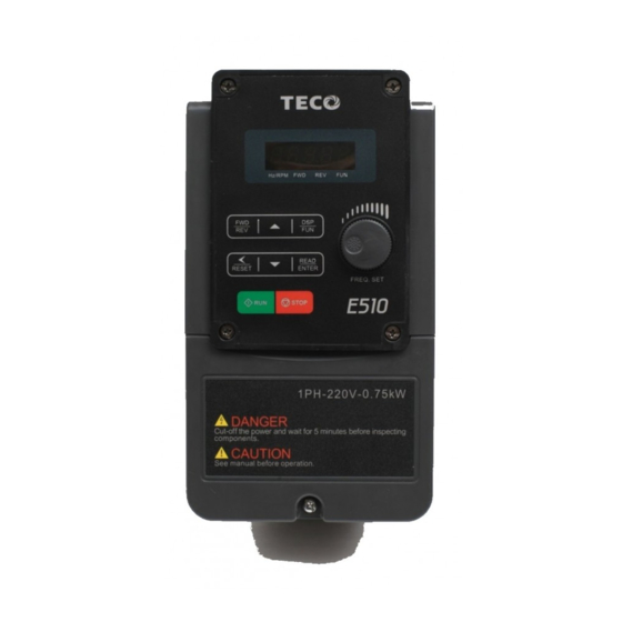
TECO E510 Series Instruction Manual
200v class 0.4-15kw, 400v class 0.75-18.5kw
Hide thumbs
Also See for E510 Series:
- Instruction manual (223 pages) ,
- Quick start manual (9 pages) ,
- Instruction manual (197 pages)
Table of Contents
Advertisement
Quick Links
Advertisement
Chapters
Table of Contents
Troubleshooting

Subscribe to Our Youtube Channel
Related Manuals for TECO E510 Series


Summary of Contents for TECO E510 Series
-
Page 2: Table Of Contents
Table of Contents Chapter 0 Preface ......................2 0.1 Preface ..........................2 Chapter 1 Safety precautions ..................3 1.1 Before power up ......................3 1.2 During power up ......................4 1.3 Before operation ......................4 1.4 During operation ......................4 1.5 Inverter Disposal ...................... -
Page 3: Chapter 0 Preface
Chapter 0 Preface 0.1 Preface To extend the performance of the product and ensure personnel safety, please read this manual thoroughly before using the inverter. Should there be any problem in using the product that cannot be solved with the information provided in the manual, contact Our’s technical or sales representative who will be willing to help you. -
Page 4: Chapter 1 Safety Precautions
Chapter 1 Safety precautions 1.1 Before Power Up Danger Make sure the main circuit connections are correct Single phase L1(L),L3(N), Three phase L1(L),L2,L3(N) are power-input terminals and must not be mistaken for T1,T2 and T3. Otherwise, inverter damage can result. Caution ... -
Page 5: During Power Up
1.2 During Power Up Danger When the momentary power loss is longer than 2 seconds, the inverter will not have sufficient stored power for its control circuit. Therefore, when the power is re-applied, the run operation of the inverter will be based on the setup of following parameters: ... -
Page 6: Inverter Disposal
Danger To avoid electric shock, do not take the front cover off while power is on. The motor will restart automatically after stop when auto-restart function is enabled. In this case, care must be taken while working around the drive and associated equipment . -
Page 7: Chapter 2 Environment & Installation
Chapter 2 Environment & Installation 2.1 Considerations for peripheral equipment Ensure that the supply voltage is correct. A molded-case circuit breaker or fused disconnect Power must be installed between the AC source and the inverter Use a molded-case circuit breaker that conforms to the rated voltage and current of the inverter. -
Page 8: Specifications
2.2 Specifications 2.2.1 Product Specifications 200V Class:Single phase Model:E510-□□□- H1F(N4)(S) Horse power (HP) 0.75 Suitable motor capacity (KW) 10.5 Rated output current (A) 2.90 4.00 Rated capacity (KVA) Single Phase:200~240V,50/60HZ Input voltage range(V) +10 %-15% Allowable voltage fluctuation Three phase: 0~240V Output voltage range(V) 23.9 Input current (A)*... - Page 9 400VClass:Three phase Model:E510-□□□- H3(F)(N4)(S) Horse power (HP) 0.75 Suitable motor capacity (KW) Rated output current (A) Rated capacity (KVA) Three phase:380~480V,50/60HZ Input voltage range(V) +10 %-15% Allowable voltage fluctuation Three phase:0~480V Output voltage range(V) 11.6 Input current (A)* Inverter net weight (KG) Allowable momentary power loss time (S) Enclosure I P 2 0 /N E M A 1 &...
-
Page 10: General Specifications
2.2.2 General Specifications Item E510 Control Mode V/F Control, Vector Control Output Frequency 0.01~599.00Hz Starting Torque 150%/1Hz(Vector) Speed Control Range 1:50 Digital input : 0.01Hz Setting resolution Analog input :0.06Hz/60Hz Keypad : Set directly with▲▼ keys or the VR on the Frequency keypad External Input Terminlas:... - Page 11 Item E510 Control Mode V/F Control, Vector Control Protection for overheating of heat sink,The carrier frequency decreasing with the temperature Other protection function,fault output,reverse prohibit,prohibit for features direct start after power up and error recovery ,parameter lock up All frames include brake transistor Standard built-in RS485 communication (Modbus), Communication control One to one or One to many control.
-
Page 12: Standard Wiring
2.3 Standard wiring 2.3.1 Single Phase: Braking resistor (Option) Main Fuse Switch L1( L) Induction Inverter Power AC Power Motor output input source L3(N) Ground 1:Data+ 2:Data- CON2 3:Data+ 4:RXD0 RS485 5:TXD0 6:Data- (Run/Stop) 7:5V Pin 1 to Pin 8 REV (Run/Stop) 8:GND Speed Control... -
Page 13: Single/Three Phase
2.3.2 Single/Three Phase Model: 200V: E510-2P5-H(N4R)/ E510-201-H(N4R)/ E510-202-H(N4R)/ E510-203-H(N4R) -
Page 14: Three Phase
2.3.3 Three phase Braking resistor (Option) Main Fuse Switch Induction Power Inverter AC Power Motor input output source Ground 1:Data+ 2:Data- CON2 3:Data+ 4:RXD0 RS485 5:TXD0 (Run/Stop) 6:Data- Pin 1 to Pin 8 7:5V REV (Run/Stop) 8:GND Speed Control Relay 250 VAC/1A Output (30VDC/1A) -
Page 15: Terminal Description
2.4 Terminal Description 2.4.1 Description of main circuit terminals Terminal symbols TM1 Function Description L1(L) Main power input:single phase: L1(L)/L3(N) single/three phase:L1(L)/L2/L3(N) three phase:L1/L2/L3 L3(N) Inverter output, connect to U/V/W terminals of motor Braking resistor connection terminal: Used in applications when it is required to stop a high inertia load rapidly. -
Page 16: Control Circuit Terminal Description
2.4.2 Control circuit terminal description Type Terminal Terminal function Signal level Forward─Stop (Preset), Multi function input terminal Reverse─Stop (Preset), Multi function input terminal 24 VDC, 8 mA, Optical Digital Preset Speed0 (5-02),Multi function input terminal coupling input isolation(Max,voltage30 Vdc, Preset Speed1 (5-03), Multi function input terminal signal Input impedance 3.3kΩ) Preset Speed2 (5-05), Multi function input terminal... -
Page 17: Outline Dimensions
2.5 Outline Dimensions mm(inch) Tolerance Table 1 ~ 10 10 ~ 50 50 ~ 100 100 ~ 200 200 ~ 400 (0.04~0.40 0.004) (0.40~1.97 0.01) (1.97~4 0.01) (4~7.87 0.02) (7.87~15.75 0.03) 2.5.1 IP20/NEMA1 dimensions Frame1 (IP20) - Page 18 Frame2 (IP20) Single/Three phase: 200V 2~3HP ; Single phase: 200V 2~3HP Three phase: 200V 5HP; 400V 3~5HP 2-Q1 2-Q2 Unit : mm(inch) Dimensions Model (Kg) E510-202-H E510-203-H E510-202-H1F E510-203-H1F 128.7 187.6 177.6 197.5 133.8 141.8 48.2 E510-205-H3 (5.07) (4.65) (4.65) (7.39) (6.99) (7.78)
- Page 19 Frame3 (IP20) Three phase: 200V 7.5~10HP; 400V 7.5~15HP 2-Q1 2-Q2 Unit : mm(inch) Dimensions Model (Kg) E510-208-H3 E510-210-H3 E510-408-H3 186.9 260.9 249.8 197.2 76.7 E510-410-H3 (7.36) (6.89) (6.93) (10.27) (9.83) (10.75) (7.76) (7.24) (7.44) (3.02) (0.18) (0.18) E510-415-H3 E510-408-H3F E510-410-H3F E510-415-H3F...
- Page 20 Frame4 (IP20) Three phase: 200V 15~20HP; 400V 20~25HP 2-Q1 2-Q2 Unit : mm(inch) Dimensions Model (Kg) E510-215-H3 10.1 E510-220-H3 10.4 224.6 321.6 303.5 330.9 200.7 187.5 192.5 (8.84) (8.15) (8.15) (12.66) (11.95) (13.03) (7.9) (7.38) (7.58) (3.7) (0.24) (0.24) E510-420-H3 10.5 E510-425-H3 10.5...
- Page 21 Frame4 (IP20) (With Filter) Three phase: 400V 20~25HP Unit : mm(inch) Dimensions Model (Kg) E510-420-H3F 13.7 224.6 303.5 330.9 200.7 187.5 192.5 192.5 (8.84) (8.15) (8.15) (17.17) (11.95) (13.03) (7.9) (7.38) (7.58) (2.52) (7.58) (0.24) (0.24) E510-425-H3F 13.7...
- Page 22 Frame4 (IP20) (With Filter) Three phase: 400V 20~25HP Unit: mm(inch) Dimensions Model (Kg) E510-420-H3FPT 13.8 235.6 381.5 249.5 254.5 (9.28) (7.09) (15.75) (15.02) (10.35) (9.82) (10.02) (2.44) (9.33) (0.28) E510-425-H3FPT 13.8...
- Page 23 Frame1 (NEMA1) Single/Three phase: 200V 0.5~1HP; Single: 200V 0.5~1HP Three phase: 200V 2HP; 400V 1~2HP Unit : mm(inch) Dimensions Model (Kg) E510-2P5-H E510-201-H E510-2P5-H1F E510-201-H1F 90.6 80.5 186.2 189.2 137.8 41.2 120.5 4.33 E510-202-H3 (3.57) (3.17) (7.33) (7.45) (5.87) (5.42) (5.55) (1.62) (4.74)
- Page 24 Frame2 (NEMA1) Single/Three phase: 200V 2~3HP; Single: 200V 2~3HP Three phase: 200V 5HP; 400V 3~5HP Unit : mm(inch) Dimensions Model (Kg) E510-202-H E510-203-H E510-202-H1F E510-203-H1F 128.7 210.6 213.6 133.8 141.8 46.1 121.1 E510-205-H3 (5.06) (4.65) (8.29) (8.41) (5.91) (5.27) (5.58) (1.81) (4.77) (0.18)
- Page 25 Frame3 (NEMA1) Three phase: 200V 7.5~10HP; 400V 7.5~15HP Unit : mm(inch) Dimensions Model (Kg) E510-208-H3 E510-210-H3 E510-408-H3 E510-410-H3 187.5 293.5 76.7 170.6 (7.38) (6.92) (11.47) (11.56) (7.76) (7.24) (7.44) (3.02) (6.72) (0.18) E510-415-H3 E510-408-H3F E510-410-H3F E510-415-H3F...
- Page 26 Frame4 (NEMA1) Three phase: 200V 15~20HP; 400V 20~25HP Unit : mm(inch) Dimensions Model (Kg) E510-215-H3 10.5 E510-220-H3 10.5 224.6 350.1 355.1 200.7 187.5 192.5 (8.84) (8.15) (13.78) (13.98) (7.9) (7.38) (7.58) (3.89) (6.85) (0.18) E510-420-H3 10.9 E510-425-H3...
-
Page 27: Ip66/Nema4X Dimensions
2.5.2 IP66/NEMA4X dimensions Frame 1(IP66/NEMA4X) Single/Three phase:200V 0.5~1HP;Single phase:200V 0.5~1HP; Three phase:200V 2HP; 400V 1~2HP Unit: mm(inch) Model Dimensions (Kg) E510-2P5-HN4R (7.87) E510-2P5-H1FN4S (7.87) (7.87) E510-201-HN4R (7.87) E510-201-H1FN4S 150.8 133.3 248.7 230.2 214.2 49.5 10.6 (7.87) (7.87) (5.94) (5.25) (9.79) (9.06) (8.43) (7.20) - Page 28 Frame 2(IP66/NEMA4X) Single/Three phase:200V 2~3HP;Single phase:200V 2~3HP; Three phase:200V5HP; 400V 3~5HP; Unit: mm(inch) Model dimensions (kg) 235.2 E510-202-HN4R (9.26) 235.2 235.2 E510-202-H1FN4S (9.26) (9.26) 235.2 E510-203-HN4R (9.26) 235.2 235.2 E510-203-H1FN4S (9.26) (9.26) 337.9 218.4 79.8 5.98 E510-205-H3N4 (7.80) (4.53) (13.19) (12.40) (13.30) (8.60)
- Page 29 Frame 3(IP66/NEMA4X) Three phase:200V 7.5~20HP; 400V 7.5~25HP Unit: mm(inch) Model Dimensions (kg) E510-208-H3N4 E510-210-H3N4 E510-215-H3N4 E510-220-H3N4 E510-408-H3N4 266.5 263.5 E510-408-H3FN4S (10.49) (10.37) 222.8 466.3 246.6 12.68 E510-410-H3N4 (8.77) (5.51) (18.11) (17.32) (18.36) (9.71) (3.78) (0.28) (0.28) 266.5 263.5 E510-410-H3FN4S (10.49) (10.37) E510-415-H3N4 266.5...
-
Page 30: Chapter 3 Software Index
Chapter 3 Software Index 3.1 Keypad Description 3.1.1 Operator Panel Functions Type Item Function Frequency Display, Parameter, voltage, Current, Main digital displays Temperature , Fault messages. Hz/RPM: ON when the frequency or line speed is displayed. OFF when the parameters are displayed. Digital FWD: ON while the inverter is running forward. -
Page 31: Programmable Parameter Groups
3.2 Programmable Parameter Groups Parameter Description Group No. Basic parameters Group V/F Pattern selections & setup Group Motor parameters Group Multi function digital Inputs/Outputs Group Analog signal inputs/ Analog output Group Preset Frequency Selections. Group Auto Run function (Auto Sequencer) Group Start/Stop command setup Group... - Page 32 G ro up 00- Basic parameters Factory Description Range Unit Note Setting 0:V/F Mode 00-00 Control Mode Selection 1:Vector Mode 00-01 Reserved 0:Keypad 1:External Run/Stop Control Main Run Command 00-02 2:Communication Source Selection 3:PLC 0:Keypad Alternative Run Command 00-03 1:External Run/Stop Control Source Selection 2:Communication 0:Forward/Stop-Reverse/Stop...
- Page 33 G ro up 01- V/F Pattern selection & Setup Factory Description Range Unit Note Setting Volts/Hz Patterns 0~18 01-00 200V:170.0~264.0 Based on 01-01 V/F Max voltage 400V:323.0~528.0 13-08 01-02 Base Frequency 0.20 ~ 599.00 50.00/60.00 01-03 Max Frequency Voltage Ratio 0.0 ~ 100.0 100.0 01-04...
- Page 34 Group 03- External Digital Inputs and Relay Output Functions Factory Description Range Unit Note Setting 03-00 Multifunction Input Term. S1 0:Forward/Stop Command 1:Reverse/Stop Command 03-01 Multifunction Input Term. S2 03-02 2:Speed Selection 1 Multifunction Input Term. S3 03-03 3:Speed Selection 2 Multifunction Input Term.
- Page 35 Group 03- External Digital Inputs and Relay Output Functions Factory Description Range Unit Note Setting 2: Output Frequency Reached ( Terminals R2A, R2B ) 3: Output Frequency Reached within Preset Range (3-13±3-14) 4: Output Frequency Detection1 (> 3-13) 5: Output Frequency Detection2 (<...
- Page 36 Group 03- External Digital Inputs and Relay Output Functions Factory Description Range Unit Note Setting 03-31 Low current detection time 0.0~50.0 ※ “NO” indicates normally open, “NC” indicates normally closed. Group 04- Analog signal inputs / Analog output Factory Description Range Unit Note...
- Page 37 Group 05- Preset Frequency Selections Factory Description Range Unit Note Setting 0: Common Accel/Decel Accel/Decel 1 or 2 apply to all speeds Preset Speed Control 05-00 1: Individual Accel/Decel for each preset speed Mode Selection 0-15 apply to the selected preset speeds (Acc0/Dec0~Acc15/Dec15) Preset Speed 0 05-01...
- Page 38 Group 05- Preset Frequency Selections Factory Description Range Unit Note Setting 05-44 10.0 Preset Speed13-Dectime 10.0 05-45 Preset Speed14-Acctime 05-46 10.0 Preset Speed14-Dectime 05-47 10.0 Preset Speed15-Acctime 05-48 10.0 Preset Speed15-Dectime Group 06- Auto Run Function (Auto Sequencer) Factory Description Range Unit Note...
- Page 39 Group 06- Auto Run Function (Auto Sequencer) Factory Description Range Unit Note Setting Auto _ Run Mode 06-12 0.00 Frequency Command Auto _ Run Mode 06-13 0.00 Frequency Command Auto _ Run Mode 06-14 0.00 Frequency Command Auto _ Run Mode 06-15 0.00 Frequency Command...
- Page 40 Group 06- Auto Run Function (Auto Sequencer) Factory Description Range Unit Note Setting Auto_ Run Mode 06-32 Running Direction 0 Auto_ Run Mode 06-33 Running Direction 1 Auto_ Run Mode 06-34 Running Direction 2 Auto_ Run Mode 06-35 Running Direction 3 Auto_ Run Mode 06-36 Running Direction 4...
- Page 41 Group 07- Start/Stop Command Setup Factory Description Range Unit Note Setting Delay-ON Timer 1.0~300.0 07-05 DC Injection Brake Start 07-06 0.10 ~ 10.00 Frequency DC Injection Brake 07-07 0.0 ~ 150.0 50.0 Level (Current Mode) DC Injection Brake 07-08 0.0 ~ 25.5 Time 0: Deceleration to stop 07-09...
- Page 42 Group 08- Drive & Motor Protection Functions Factory Description Range Unit Note Setting xxx0b: Overload Protection is Disabled xxx1b: Overload Protection is Enabled Electronic Motor xx0xb: Cold Start of Motor Overload 08-05 Overload Protection 0001b xx1xb: Hot Start of Motor Overload Operation Mode x0xxb: Standard Motor x1xxb: Inverter Duty Motor...
- Page 43 Group 09- Communication function setup Factory Description Range Unit Note Setting Assigned Communication 09-00 1 ~ 32 *2*3 Station Number 0: RTU Code 09-01 RTU/ASCII Code Selection *2*3 1: ASCII Code 0: 4800 1: 9600 09-02 *2*3 Baud Rate Setting (bps) 2: 19200 3: 38400 0: 1 Stop Bit...
- Page 44 Group 10- PID Function Setup Factory Description Range Unit Note Setting 0.0 ~ 10.0 10-05 Proportional Gain 10-06 0.0 ~ 100.0 10.0 Integral Time 10-07 Derivative Time 0.00 ~ 10.00 0.00 0: Positive 10-08 PID Offset 1: Negative 10-09 PID Offset Adjust 0 ~ 109 10-10 0.0 ~ 2.5...
- Page 45 Group 11- Performance Control Functions Factory Description Range unit Note Setting Skip Frequency Range 11-11 0.00 ~ 30.00 0.00 Bandwith (±) Energy Saving Gain (V/F 0 ~ 100 11-12 Mode) 0:Disable Regeneration Prevention 1:Enable 11-13 Function 2:Enable (only during constant speed) 200V:300.0~400.0 380.0 Regeneration Prevention...
- Page 46 Group 12 Digital Display & Monitor Functions Factory Description Range Unit Note Setting S2 S3 S4 S5 Inputs and Output 12-05 Logic Status Display ( S1~S6, RY1 and RY2) xxxx0:Life Alarm of Inrush Current Suppression Circuit is Invalid xxxx1:Life Alarm of Inrush Current Suppression Circuit is Valid xxx0x:Life Alarm of Control Circuit Alarm Selections for Inverter...
- Page 47 Group 13 Inspection & Maintenance Functions Factory Description Range unit Note Setting 13-00 Drive Horsepower Code ---- 13-01 Software Version ---- *3*4 Fault Log (Latest 3 13-02 ---- *3*4 Faults) Accumulated Inverter 13-03 0~23 hour Operation Time 1 Accumulated Inverter 13-04 0~65535 ----...
- Page 48 Group 14 PLC Setting function Factory Description Range unit Note Setting 14-00 Setting Value1 of T1 0~9999 Setting Value1 of T1 (mode 7) 14-01 0~9999 14-02 Setting Value1 of T2 0~9999 14-03 Setting Value1 of T2 (mode 7) 0~9999 14-04 Setting Value1 of T3 0~9999 14-05...
- Page 49 Group 15 PLC Monitoring function Factory Description Range unit Note Setting 15-00 Current Value of T1 0~9999 Current Value of T1(mode 7) 15-01 0~9999 15-02 Current Value of T2 0~9999 15-03 Current Value of T2(mode 7) 0~9999 15-04 Current Value of T3 0~9999 15-05 Current Value of T3(mode 7)
-
Page 50: Chapter 4 Troubleshooting And Maintenance
Chapter 4 Troubleshooting and Maintenance 4.1 Error display and corrective action 4.1.1 Manual Reset and Auto-Reset Faults which can not be recovered manually Display content Cause Corrective action -OV- Voltage too high Detection circuit malfunction Consult with the supplier when stopped -LV- 1. - Page 51 Display content Cause Corrective action OC-C 1.Increase the capacity of Over-current at 1.Transient load change the inverter fixed speed 2.Transient power change 2.Install inductor on the power Supply input side OC-d Over-current at The preset deceleration time Set a longer deceleration deceleration is too short.
-
Page 52: Keypad Operation Error Instruction
Faults which can be recovered manually but not automatically Display content Cause Corrective action LIFE1 Inrush current suppression Inrush current suppression Consult with the supplier circuit life circuit is damaged expectancy alarm LIFE2 Control circuit Control circuit capacitor is capacitor life Consult with the supplier damaged expectancy alarm... -
Page 53: Special Conditions
Display content Cause Corrective action Err7 1.Attempt to modify the function 13-00/13-08. If reset is not possible, please Parameter conflict 2.Voltage and current consult with the supplier. detection circuit is abnormal. 4.1.3 Special conditions Display Fault Description StP0 Zero speed at Occurs when preset frequency <0.1Hz stop If the inverter is set for external terminal control mode... -
Page 54: General Troubleshooting
4.2 General troubleshooting Status Checking point Remedy Is the wiring for the output Wiring must match U, V, and W terminals of Motor runs terminals correct? the motor. in wrong Is the wiring for forward and direction Check for correct wiring. reverse signals correct? Is the wiring for the analog Check for correct wiring. - Page 55 目錄 第 0 章 前言 ........................... 2 0.1 前言 ..........................2 第 1 章 安全注意事項 ......................3 1.1 送電前 ..........................3 1.2 送電中 ..........................4 1.3 運轉前 ..........................5 1.4 運轉中 ..........................6 1.5 檢查保養和更換時 ......................7 第 2 章 周圍環境及安裝 ....................
-
Page 56: 第 0 章 前言
第 0 章 前言 0.1 前言 為了充分地發揮本變頻器的功能及確保使用者的安全,請詳閱本操作手冊。當您在使用 過程中發現疑難問題時,請與各地經銷商或本公司技術人員聯繫,我們的專業人員會樂於為 您服務。 ※使用須知 變頻器是精密的電力電子產品,為保障您的生命財產安全,本手冊中有「危險」「注意」 等字樣,是為提醒您在搬運、安裝、使用、檢查變頻器時所需關注的安全防範事項,請您配 合遵守。 危 險 操作不當時,可能造成嚴重的人身傷害。 注 意 操作不當時,可能造成變頻器或機械系統損壞。 危 險 避免感電!變頻器內部的直流電容器在電源移除後 5 分鐘才能放電完畢 , 請在電源移除後 5 分鐘,再進行拆裝或實施檢查。 不可在送電過程中實施配線,變頻器處於運行狀態時請勿檢查線路板; 請勿自行拆裝更改變頻器內部連接線或線路及零件; 變頻器接地端子請務必正確接地。 注 意 請勿對變頻器內部的零元件進行耐壓測試,這些半導體零件易受高電壓損毀; 絕不可將變頻器輸出端子... -
Page 57: 第 1 章 安全注意事項
第 1 章 安全注意事項 1.1 送電前 警告 主回路端子必須正確配線,單相 L1(L) 、L3(N)、三相 L1(L)、L2、L3(N)為電源輸入端 子,絕對不可以與 T1、T2、T3 混用;混用時,送電將造成變頻器的損壞。 注意 所選用之電源電壓必須與變頻器之輸入電壓規格相同。 搬運變頻器時,請勿直接提取前蓋,應由變頻器本體搬運,以防止前蓋脫落,避免變頻 器掉落造成人員受傷或變頻器損壞。 請將變頻器安裝於金屬類等不燃物材料之上,請勿安裝於易燃性材料上或附近,以防止 發生火災。 若多台變頻器同放在一個控制盤內,請外加散熱風扇,使盤內溫度低於 40℃ 以下,以 防過熱或火災等發生。 請於關閉電源後,再拆卸或裝入操作器,並請按圖操作固定操作器,以免接觸不良造成 操作器故障或不顯示。 本產品所提供的電源(10V/24V)僅供產品內部接點使用,請勿使用於其他外部元件的電源 供應來源,如 感應器、電子元件...等,否則會造成產品使用不良的情況。 警告 本產品系通過 IEC 61800-3 和 IEC 61800-5-1 限制區域使用等級。在某些環境下使用本 產品時,可能造成電磁干擾,故在使用前請先進行適當的測試,同時請務必做好接地工... -
Page 58: 送電中
1.2 送電中 警告 實施任何變頻器裝機或配線前,請務必關上總電源,避免觸電及火災發生。 配線工程人員須具備相關專業知識,避免觸電與火災發生。 確認接地線與大地連接。(220V 級:接地阻抗需低於 100 歐姆; 440V 級:接地阻抗需低於 10 歐姆) 接線完成後,確認緊急停止機能有效。(接線責任屬於使用方) 勿直接觸碰輸入/輸出電源線,並避免所有接線與變頻器外殼接觸與線路短路。 勿對變頻器進行耐壓測試,容易造成半導體元件受損。 注意 確認輸入主電源與變頻器相符,避免受傷或火災發生。 請依相關接線圖連接煞車電阻及煞車單元,否則有引發火災危險。 請依指定轉矩來鎖固端子螺絲,避免引發火災的危險。 勿將輸入電源連接至變頻器輸出端子上。 勿將電磁接觸器,電磁開關接點連接至輸出端子。 勿將進相電容器或 LC/RC 濾波器連接至輸出電路上。 確保變頻器、馬達所產生的干擾不會影響周邊感測器或設備。... -
Page 59: 運轉前
警告 若停電時間大於兩秒(功率越大,可允許斷電時間愈長),會使變頻器失去控制電源, 故在電源恢復送電以後,變頻器運行與否,是根據 00- 02(或 00- 03)及 07- 04 參數的設 定及外部開關的狀態而決定,此時視為重新開機。 若停電時間短,變頻器仍擁有控制電源,因此當電源恢復時,變頻器能否自行啟動,將 取決於 07- 00 參數的設定。 當重新開機時,變頻器運轉與否,取決於 00- 02(或 00- 03)及 07- 04 的設定及電源開關/ 運轉開關(FWD/REV 開關)的狀態(與 07- 00/07- 01/07- 02): 1. 00- 02(或 00- 03)=0 時,重新開機後,不會自動啟動。 2. 00- 02(或 00- 03)=1 且電源開關或運轉開關(FWD/REV 開關)關斷時,重新開機後, 不會自動啟動。... -
Page 60: 運轉中
1.4 運轉中 警告 請確認前外蓋安裝完成後,再打開電源。 運轉中不可將馬達機組投入或切離,否則會造成變頻器過電流跳脫,嚴重時會造成變頻 器主回路損壞。 進行復歸機能時,請勿靠近機器,故障清除後,機器會再啟動。 勿於雙手潮濕時操作機器。 如設定自動再啟動功能時,馬達於運轉停止後會自動再啟動,請勿靠近機器以免危險。 復歸警告前請確認運轉命令為關閉的。 若選擇復電後自動重新啟動(07-00),變頻器將在電源回復後自動啟動。 無論變頻器處於運轉或停止狀態,避免觸碰相關端子,以防發生危險。 避免感電!變頻器內部的直流電容器在電源移除後 5 分鐘才能放電完畢,請在電源移除 5 分鐘後,再進行拆裝或實施檢查。 注意 散熱座、煞車電阻等發熱元件請勿觸摸。 變頻器可以很容易使馬達從低速到高速運轉,請確認馬達與機械的容許範圍。 使用煞車模組等搭配產品時,請注意其使用之相關設定。 電源切斷後,風扇可能會繼續旋轉一段時間。 變頻器運轉時,請勿檢查電路板上的信號。... -
Page 61: 檢查保養和更換時
1.5 檢查保養和更換時 警告 進行維護檢查前,請先確認電源已經關閉且電源指示燈熄滅(請確認直流電壓不超過 25 伏特)。 變頻器端子中有高壓端子,請勿隨意觸摸。 電源開啟情況下,請務必安裝保護蓋,另拆卸保護蓋後,請務必透過斷路器斷開電源。 除指定的專業人員外,他人請勿進行保養檢查或更換零件。 注意 變頻器周圍溫度應在 -10℃~+50℃* 95%RH 不結露環境中使用,但需確保周 圍環境無滴水及金屬粉塵。 * -10℃~+50℃ (無防塵蓋/防塵貼紙) -10℃~+40℃ (有防塵蓋/防塵貼紙) 變頻器報廢時注意事項 注意 當變頻器要處理報廢時,請作為工業垃圾進行處理,並請注意以下事項: 變頻器主回路的電解電容和印刷電路板上的電解電容焚燒時可能會發生爆炸; 變頻器的外殼等塑膠件焚燒時會產生有毒氣體。 裝有電子元件的設備不能與生活垃圾一起處理 , 必須按照地方現行法規將其與電氣和電子廢 棄物一起單獨回收。... -
Page 62: 第 2 章 周圍環境及安裝
第 2 章 周圍環境及安裝 2.1 週邊設備應用及注意事項 週邊設備 請注意電壓等級是否正確,以免損壞變頻器。 電源 交流電源與變頻器之間必須安裝無熔絲斷路器。 請使用與變頻器額定電壓、電流等級相符的無熔絲斷路器 做變頻器供電電源的通/斷控制,並做為變頻器的保護裝 無 熔 絲 置使用。 斷 路 器 無熔線斷路器請不要做為變頻器的運轉/停止切換功能使 用。 漏 電 斷 如若加裝漏電斷路器作漏電故障保護時,請選用感度電流 路 器 200mA 以上,動作時間為 0.1 秒以上的器具,以防高頻誤 動作。 一般使用時,可以不加電磁接觸器,但要作外部順序控制 電 磁 接 觸... -
Page 63: 產品個別規格
2.2 規格 2.2.1 產品個別規格 單相 200V 機種 型 號 : E510-□□□- H1F(N4)(S) 馬 力 數 (HP) 適 用 馬 達 容 量 (KW) 0.75 額 定 輸 出 電 流 (A) 10.5 額 定 容 量 (KVA) 2.90 4.00 單 相 : 200~240V,50/60HZ 輸... - Page 64 三相 200V 機種 型 號 : E510-□□□- H3(N4) 馬 力 數 (HP) 適 用 馬 達 容 量 (KW) 額 定 輸 出 電 流 (A) 17.5 額 定 容 量 (KVA) 13.3 20.6 27.4 三相 : 200~240V,50/60HZ 輸 入 電 壓 範 圍 容許電壓變動...
- Page 65 型 號 : E510-□ □ □ - H3(F)(PT) 馬 力 數 (HP) 適 用 馬 達 容 量 (kW) 18.5 額 定 輸 出 電 流 (A) 額 定 容 量 (kVA) 30.5 三 相 380~ 480V (+10 %-15 %),50/60HZ 輸...
-
Page 66: 產品共通規格
2.2.2 產品共通規格 項目 E510 V/F 控制或向量控制功能 控制方式 0.01~599.00Hz 頻率控制範圍 150% / 1Hz (向量模式) 啟動轉矩 數位輸入: 0.01Hz 頻率解析度 類比輸入:0.06Hz/60Hz 頻 面板:·使用面板▲▼ 鍵設定頻率,面板旋鈕設定頻率 率 外部端子: ·AI1、AI2 (0~10V / 2~10V / 0~20mA / 4~20mA) 輸入 頻率設定 up/down 頻率設定 通訊設定 頻率上、下限 ·3 段跳躍頻率可以設定 頻率限制 面板:run、stop 鍵控制... -
Page 67: 標準配線
2.3 標準配線 2.3.1 單相: 適用型號: 200V: E510-2P5-H1(F)(N4S)/ E510-201-H1(F) (N4S)/ E510-202-H1(F)(N4S)/E510-203-H1(F) (N4S) - Page 68 2.3.2 單/三相: 適用型號: 200V: E510-2P5-H(N4R)/ E510-201-H(N4R)/ E510-202-H(N4R)/ E510-203-H(N4R)
- Page 69 2.3.3 三相: 適用型號: 200V:E510-202-H3(N4)/E510-205-H3(N4)/E510-208-H3(N4)/E510-210-H3(N4)/ E510-215-H3(N4)/E510-220-H3(N4) 400V:E510-401-H3(F)(N4)(S)/ E510-402-H3(F)(N4)(S)/ E510-403-H3(F)(N4)(S)/ E510-405-H3(F)(N4)(S)/ E510-408-H3(F)(N4)(S)/E510-410-H3(F)(N4)(S)/ E510-415-H3(F)(N4)(S)/ E510-420-H3(F)(N4)/E510-425-H3(F)(N4) E510-420-H3FPT/E510-425-H3FPT...
-
Page 70: 端子說明
2.4 端子說明 2.4.1 主迴路端子說明 TM1 端子功能說明 端子符號 L1(L) 交流電源輸入端:單相:L1(L)、L3(N) 單/三相:L1(L)、L2、L3(N) L3(N) 三相:L1、L2、L3 變頻器的輸出端,連接馬達 U、V、W 端 制動電阻連接端子,當負載慣量大或減速時間短,而使變頻器容易過電壓跳脫時使 用(參照制動電阻規格) 接地端子 2.4.2 控制迴路端子說明 種類 端子 端子功能 信號準位 正轉運轉─停止命令 (預設),多功能輸入端子*1 反轉運轉─停止命令 (預設),多功能輸入端子*1 多段速設定位 0(5-02),多功能輸入端子*1 24 VDC, 8 mA 光耦合隔離(最大 數位輸 多段速設定位 1(5-03),多功能輸入端子*1 電壓 30 Vdc, 輸入阻抗 3.3kΩ) 入信號... - Page 71 控制迴路端子:...
-
Page 72: 外形尺寸圖
2.5 外形尺寸圖 單位:mm(inch) 公差表 1 ~ 10 10 ~ 50 50 ~ 100 100 ~ 200 200 ~ 400 (0.04~0.40 0.004) (0.40~1.97 0.01) (1.97~4 0.01) (4~7.87 0.02) (7.87~15.75 0.03) 2.5.1 IP20/NEMA1 型產品外形尺寸 Frame1 (IP20) (單/三相:200V 0.5~1HP;單相:200V 0.5~1HP;... - Page 73 Frame2 (IP20) (單/三相:200V 2~3HP;單相:200V 2~3HP;三相:200V 5HP; 400V 3~5HP) 2-Q1 2-Q2 單位:mm(inch) 尺寸 重量 型號 (Kg) E510-202-H E510-203-H E510-202-H1F E510-203-H1F 128.7 187.6 177.6 197.5 133.8 141.8 48.2 E510-205-H3 (5.07) (4.65) (4.65) (7.39) (6.99) (7.78) (5.91) (5.27) (5.58) (1.9) (0.18) (0.18) E510-403-H3 E510-405-H3 E510-403-H3F E510-405-H3F...
- Page 74 Frame3 (IP20) (三相:200V 7.5~10HP;400V 7.5~15HP) 2-Q1 2-Q2 單位:mm(inch) 尺寸 重量 型號 (Kg) E510-208-H3 E510-210-H3 E510-408-H3 186.9 260.9 249.8 197.2 76.7 E510-410-H3 (7.36) (6.89) (6.93) (10.27) (9.83) (10.75) (7.76) (7.24) (7.44) (3.02) (0.18) (0.18) E510-415-H3 E510-408-H3F E510-410-H3F E510-415-H3F...
- Page 75 Frame4 (IP20) (三相:200V 15~20HP; 400V 20~25HP) 2-Q1 2-Q2 單位:mm(inch) 尺寸 重量 型號 (Kg) E510-215-H3 10.1 E510-220-H3 10.4 224.6 321.6 303.5 330.9 200.7 187.5 192.5 (8.84) (8.15) (8.15) (12.66) (11.95) (13.03) (7.9) (7.38) (7.58) (3.7) (0.24) (0.24) E510-420-H3 10.5 E510-425-H3 10.5...
- Page 76 Frame4 (IP20) (内建 EMC 濾波器) (三相:400V 20~25HP) 單位:mm(inch) 尺寸 重量 型號 (Kg) E510-420-H3F 13.7 224.6 303.5 330.9 200.7 187.5 192.5 192.5 (8.84) (8.15) (8.15) (17.17) (11.95) (13.03) (7.9) (7.38) (7.58) (2.52) (7.58) (0.24) (0.24) E510-425-H3F 13.7...
- Page 77 Frame4(IP20)(内建 EMC 滤波器) (三相:400V 20~25HP) 單位:mm(inch) 尺寸 重量 型號 (kg) E510-420-H3FPT 13.8 235.6 381.5 249.5 254.5 (9.28) (7.09) (15.75) (15.02) (10.35) (9.82) (10.02) (2.44) (9.33) (0.28) E510-425-H3FPT 13.8...
- Page 78 Frame1(NEMA1)( 單/三相: 200V 0.5~1HP; 單相: 200V 0.5~1HP; 三相: 200V 2HP; 400V 1~2HP) 單位:mm(inch) 尺寸 重量 型號 (Kg) E510-2P5-H E510-201-H E510-2P5-H1F E510-201-H1F 90.6 80.5 186.2 189.2 137.8 41.2 120.5 4.33 E510-202-H3 (3.57) (3.17) (7.33) (7.45) (5.87)) (5.42) (5.55 (1.62) (4.74) (0.17) E510-401-H3 E510-402-H3 E510-401-H3F...
- Page 79 Frame2(NEMA1)( 單/三相:200V 2~3HP;單相:200V 2~3HP;三相:200V 5HP; 400V 3~5HP) 單位:mm(inch) 尺寸 重量 型號 (Kg) E510-202-H E510-203-H E510-202-H1F E510-203-H1F 128.7 210.6 213.6 133.8 141.8 46.1 121.1 E510-205-H3 (5.06) (4.65) (8.29) (8.41) (5.91) (5.27) (5.58) (1.81) (4.77) (0.18) E510-403-H3 E510-405-H3 E510-403-H3F E510-405-H3F...
- Page 80 Frame3(NEMA1)( 三相:200V 7.5~10HP;400V 7.5~15HP) 單位:mm(inch) 尺寸 重量 型號 (Kg) E510-208-H3 E510-210-H3 E510-408-H3 E510-410-H3 187.5 293.5 76.7 170.6 (7.38) (6.92) (11.47) (11.56) (7.76) (7.24) (7.44) (3.02) (6.72) (0.18) E510-415-H3 E510-408-H3F E510-410-H3F E510-415-H3F...
- Page 81 Frame4(NEMA1)( 三相:200V 15~20HP; 400V 20~25HP) 單位:mm(inch) 尺寸 重量 型號 (Kg) E510-215-H3 10.5 E510-220-H3 10.5 224.6 350.1 355.1 200.7 187.5 192.5 (8.84) (8.15) (13.78) (13.98) (7.9) (7.38) (7.58) (3.89) (6.85) (0.18) E510-420-H3 10.9 E510-425-H3...
-
Page 82: Ip66/Nema4X 型產品外形尺寸
2.5.2 IP66/NEMA4X 型產品外形尺寸 Frame 1(IP66/NEMA4X) (單/三相:200V 0.5~1HP;單相:200V 0.5~1HP; 三相:200V 2HP;400V 1~2HP) 單位:mm(inch) 重量 型號 尺寸 (Kg) E510-2P5-HN4R (7.87) E510-2P5-H1FN4S (7.87) (7.87) E510-201-HN4R (7.87) E510-201-H1FN4S 150.8 133.3 248.7 230.2 214.2 49.5 10.6 (7.87) (7.87) (5.94) (5.25) (9.79) (9.06) (8.43) (7.20) (1.95) (0.21) (0.21) (0.42) - Page 83 Frame 2(IP66/NEMA4X) (單/三相:200V 2~3HP;單相:200V 2~3HP; 三相:200V5HP;400V 3~5HP;) 單位:mm(inch) 重量 型號 尺寸 (kg) 235.2 E510-202-HN4R (9.26) 235.2 235.2 E510-202-H1FN4S (9.26) (9.26) 235.2 E510-203-HN4R (9.26) 235.2 235.2 E510-203-H1FN4S (9.26) (9.26) 337.9 218.4 79.8 5.98 E510-205-H3N4 (7.80) (4.53) (13.19) (12.40) (13.30) (8.60) (3.14) (0.28) (0.28) E510-403-H3N4...
- Page 84 Frame 3(IP66/NEMA4)(三相:200V 8~20HP; 400V 8~25HP) 單位:mm(inch) 重量 型號 尺寸 (kg) E510-208-H3N4 E510-210-H3N4 E510-215-H3N4 E510-220-H3N4 E510-408-H3N4 266.5 263.5 E510-408-H3FN4S (10.49) (10.37) 222.8 466.3 246.6 12.68 E510-410-H3N4 (8.77) (5.51) (18.11) (17.32) (18.36) (9.71) (3.78) (0.28) (0.28) 266.5 263.5 E510-410-H3FN4S (10.49) (10.37) E510-415-H3N4 266.5 263.5 E510-415-H3FN4S...
-
Page 85: 第 3 章 軟體索引
第 3 章 軟體索引 3.1 面板功能說明 類型 名稱 功能 顯示頻率、參數、以及電壓、電流、溫度及異常等 Hz/RPM:頻率信號指示燈 主顯示區 FWD:當變頻器處於正轉狀態時,此指示燈被點亮 (五位 8 段數碼管) 顯示 (停機時閃爍,運轉後則處於長亮狀態) 狀態顯示區 REV:當變頻器處於反轉狀態時,此指示燈被點亮 (停機時閃爍,運轉後則處於長亮狀態) FUN:當面板顯示參數功能表時,此指示燈被點亮 旋鈕 面板旋鈕 可設定頻率 RUN 鍵 RUN 鍵:可令變頻器運轉 STOP 鍵 STOP 鍵:可令變頻器停止運轉 FWD/REV 鍵 FWD 鍵:切換至正轉 REV 鍵:切換至反轉 (雙功能鍵) DSP/FUN 鍵... -
Page 86: 參數一覽表
3.2 參數一覽表 參數群組 名 稱 群組 00 基本功能群組 群組 01 V/F 控制功能群組 群組 02 馬達參數群組 群組 03 外部端子數位輸入輸出功能群組 群組 04 外部端子類比輸入輸出功能群組 群組 05 多段速功能群組 群組 06 自動程式運轉功能群組 群組 07 啟動停止控制功能群組 群組 08 保護功能群組 群組 09 通訊功能群組 群組 10 PID 功能群組 群組... - Page 87 群組 00-基本功能群組 代碼 參數名稱 範圍 出廠設定 單位 屬性 0:V/F 模式 00-00 控制模式 1:向量模式 00-01 預留 0:按鍵面板控制 1:外部端子控制 00-02 主運轉命令來源選擇 2:通訊控制 3:PLC 0:按鍵面板控制 1:外部端子控制 00-03 副運轉命令來源選擇 2:通訊控制 0:正轉/停止-反轉/停止 1:運轉/停止-正轉/反轉 00-04 多功能端子運轉模式選擇 2:3 線制運轉/停止 0:按鍵面板上下鍵設定 1:按鍵面板旋鈕設定 2:外部端子 AI1 設定 3:外部端子 AI2 設定 00-05 主頻率命令來源選擇...
- Page 88 群組 01-V/F 控制功能群組 代碼 參數名稱 範圍 出廠設定 單位 屬性 V/F 曲線選擇 01-00 0~18 200V:170.0~264.0 依據 13-08 V/F 最大輸出電壓 01-01 400V:323.0~528.0 決定 01-02 基底頻率 0.20 ~ 599.00 50.00/60.00 01-03 最大輸出電壓比 0.0 ~ 100.0 100.0 中間輸出頻率 2 01-04 0.10 ~ 599.00 25.00/30.00 中間輸出電壓比...
- Page 89 群組 03-外部端子數位輸入輸出功能群組 出廠 代碼 參數名稱 範圍 單位 屬性 設定 7:寸動反轉指令 8:Up 增頻率指令 9:Down 減頻率指令 10:加/減速時間 2 11:加/減速禁止 12:主/副運轉命令切換 13:主/副頻率命令切換 14:緊急停止(減速到零停止) 15:遮斷停止(自由運轉停止) 16:PID 功能禁止 17:故障複歸(Reset) 18:自動程式運轉 19:速度搜尋 20:節能運行(僅 V/F) 21:PID 積分器歸零 22:計數器觸發信號輸入 23:計數器歸零指令 24:PLC 應用 25:脈衝輸入-脈衝寬度測量 (S3) 26:脈衝輸入-脈衝頻率測量(S3) 27:電源電壓偵測電能回升功能 28:火災模式輸入(軟體 V1.1 版以上) up/down 頻率幅寬設定...
- Page 90 群組 03-外部端子數位輸入輸出功能群組 出廠 代碼 參數名稱 範圍 單位 屬性 設定 11:變頻器超載保護(OL2) 12:過轉矩檢出(OL3) 13:電流到達(03-15~16) 14:機械煞車控制功能 (03-17~18) 15:PID 回授斷線檢出 16:設定計數值到達指示(3-22) 17:指定計數值到達指示(3-22~23) 18:PLC 狀態指示(00-02) 19:PLC 控制 20:零速功能 21:低電流檢出 03-13 0.00 任意頻率到達設定 0.00~599.00 03-14 2.00 頻率輸出偵測範圍(±) 0.00~30.00 03-15 電流到達準位 0.1~999.9 03-16 電流到達檢測延遲時間 0.1~10.0 03-17 0.00 機械煞車釋放準位設定...
- Page 91 群組 04-外部端子類比輸入輸出功能群組 代碼 參數名稱 範圍 出廠設定 單位 屬性 【0】: 0~10V (0~20mA) 0~10V (0~20mA) AI1 與 AI2 輸入信號種類 04-00 【1】: 0~10V (0~20mA) 2~10V (4~20mA) 【2】: 2~10V (4~20mA) 0~10V (0~20mA) 【3】: 2~10V (4~20mA) 2~10V (4~20mA) AI1 信號掃描濾波時間 04-01 1~200 2mSec AI1 增益值 04-02 0 ~ 1000 AI1 偏置值...
- Page 92 群組 05-多段速功能群組 代碼 參數名稱 範圍 出廠設定 單位 屬性 多段速 11 頻率設定 0.00 ~ 599.00 05-12 0.00 多段速 12 頻率設定 0.00 ~ 599.00 05-13 0.00 多段速 13 頻率設定 0.00 ~ 599.00 05-14 0.00 多段速 14 頻率設定 0.00 ~ 599.00 05-15 0.00 0.00 ~ 599.00 多段速...
- Page 93 群組 06-自動程式運轉功能群組 代碼 參數名稱 範圍 出廠設定 單位 屬性 0:自動程式運轉無效 1:執行單一週期之自動運轉模式,停止後 會由停止前的速度起,繼續運轉 2:連續迴圈週期之自動運轉模式,停止後 會由停止前的速度起,繼續運轉 3:單一週期結束後,以最後一段運轉速度 繼續運轉;停止後會由停止前的速度起,繼 自動程式運轉模式選 06-00 續運轉 擇 4:執行單一週期之自動運轉模式,停止後會 從第一段速起,開始運轉 5:連續迴圈週期之自動運轉模式,停止後 會從第一段速起,開始運轉 6:單一週期結束後,以最後一段運轉速度 繼續運轉;停止後會從第一段速起,開始 運轉 第 0 段速的頻率通過參數 05-01 來設定 0.00 ~ 599.00 第 1 段速頻率設定 06-01 0.00 第 2 段速頻率設定 0.00 ~ 599.00 06-02 0.00...
- Page 94 群組 06-自動程式運轉功能群組 代碼 參數名稱 範圍 出廠設定 單位 屬性 第 4 段運行轉向選擇 0:停止 1:正轉 2:反轉 06-36 第 5 段運行轉向選擇 0:停止 1:正轉 2:反轉 06-37 第 6 段運行轉向選擇 0:停止 1:正轉 2:反轉 06-38 第 7 段運行轉向選擇 0:停止 1:正轉 2:反轉 06-39 第 8 段運行轉向選擇 0:停止 1:正轉...
- Page 95 群組 08-保護功能群組 代碼 參數名稱 範圍 出廠設定 單位 屬性 xxxx0:加速時失速防止有效 xxxx1:加速時失速防止無效 xxx0x:減速時失速防止有效 xxx1x:減速時失速防止無效 08-00 01000 失速防止功能 xx0xx:運轉中失速防止有效 xx1xx:運轉中失速防止無效 x0xxx:運轉中過電壓防止有效 x1xxx:運轉中過電壓防止無效 額定電流 08-01 50 ~ 200 加速失速防止準位 的 100% 額定電流 08-02 50 ~ 200 減速失速防止準位 的 100% 額定電流 08-03 運轉失速防止準位 50 ~ 200 的...
- Page 96 群組 08-保護功能群組 代碼 參數名稱 範圍 出廠設定 單位 屬性 0.0~25.0 08-16 過轉矩偵測時間 0:無效 火災模式 08-17 1:有效 0:無效 輸出側接地過電流檢 08-18 1:有效 測 0:馬達過載(OL1)保護 0 馬達過載(OL1)保護 1:馬達過載(OL1)保護 1 08-19 準位 0:馬達過載(OL1)保護 2 Notes:08-17 功能修正,軟體 V1.1 版以上,併入多機能端子 03-00 ~ 03-05 (28 火災模式輸入)設定使用。 08-18 僅對 frame3, 4 機種別可出現 群組...
- Page 97 群組 10-PID 功能群組 代碼 參數名稱 範圍 出廠設定 單位 屬性 0:Keypad 旋鈕設定 1:類比 AI1 設定 PID 目標值來源設定 (00-05 或 00-06=6 2:類比 AI2 設定 10-00 3:通訊設定 此參數功能啟用) 4:由 10-02 設定 0:Keypad 旋鈕設定 1:類比 AI1 設定 PID 回授值來源設定 10-01 2:類比 AI2 設定 3:通訊設定 PID 鍵盤設定...
- Page 98 群組 11 輔助功能群組 代碼 參數名稱 範圍 出廠設定 單位 屬性 0:反轉指令有效 11-00 反轉禁止指令 1:反轉指令無效 1~16 11-01 載波頻率 0:載波模式 0 三相調變 11-02 1:載波模式 1 兩相調變 載波模式選擇 2:載波模式 2 兩相軟調變 0:降低載波無效 11-03 載波頻率隨溫度降低選擇 1:降低載波有效 第 1 段加速 S 曲線時間設定 0.0 ~ 4.0 11-04 第...
- Page 99 群組 12 監視功能群組 代碼 參數名稱 範圍 出廠設定 單位 屬性 00000~88888 每一位的範圍為 0~8 0:不顯示畫面 1:變頻器輸出電流 2:變頻器輸出電壓 3:變頻器直流電壓 12-00 00000 顯示畫面選擇 4:溫度 5:PID 回授值 6:AI1 值 7:AI2 值 8:計數值 0:以整數顯示回授值(xxx) PID 回授顯示模式 1:以小數點 1 位元顯示回授值(xx.x) 12-01 2:以小數點 2 位元顯示回授值(x.xx) 0:xxx__(無單位) PID 回授顯示單位設定 1:xxxpb(壓力) 12-02 2:xxxfl(流量)
- Page 100 群組 12 監視功能群組 代碼 參數名稱 範圍 出廠設定 單位 屬性 ---- 12-16 輸出功率顯示 輸出功率顯示(參數 12-16)需要正確設定馬達額定功率(參數 02-05) 群組 13 維護功能群組 代碼 參數名稱 範圍 出廠設定 單位 屬性 變頻器馬力值 13-00 ---- 13-01 軟體版本 ---- *3*4 13-02 故障記錄 ---- *3*4 累積工作時間 1 小時 13-03 0~23 累積工作時間...
- Page 101 群組 14 PLC 設定群組 代碼 參數名稱 範圍 出廠設定 單位 屬性 T1 設定值 1 14-00 0~9999 T1 設定值 2(模式 7) 14-01 0~9999 T2 設定值 1 14-02 0~9999 T2 設定值 2(模式 7) 14-03 0~9999 T3 設定值 1 14-04 0~9999 T3 設定值 2(模式 7) 14-05 0~9999 T4 設定值...
- Page 102 群組 15 PLC 監控群組 代碼 參數名稱 範圍 出廠設定 單位 屬性 T1 當前值 0~9999 15-00 T1 當前值 2(模式 7) 0~9999 15-01 T2 當前值 15-02 0~9999 T2 當前值 2(模式 7) 15-03 0~9999 T3 當前值 15-04 0~9999 T3 當前值 2(模式 7) 15-05 0~9999 T4 當前值...
-
Page 103: 第 4 章 異常診斷及保養
第 4 章 異常診斷及保養 4.1 故障顯示及對策 4.1.1 手動復歸與自動復歸 無法手動復歸且無法自動復歸的故障 顯 示 內 容 異 常 原 因 對 策 -OV- 停機中電壓過高 偵測線路故障 變頻器送修 -LV- 1.電源電壓過低 1.檢查電源電壓是否正常 2.限流電阻(R1)或保險絲燒 2.換修限流電阻或保險絲 停機中電壓過低 斷 3.變頻器送修 3.偵測線路故障 -OH- 1.周溫過熱或通風不良 1.改善通風條件 停機中變頻器過熱 2.偵測線路故障 2.變頻器送修 OH-C 1.周溫過熱或通風不良 1.改善通風條件... - Page 104 顯 示 內 容 異 常 原 因 對 策 OC-d 減速時過電流 減速時間設定太短 設定較長的減速時間 OC-S 1.馬達繞組與外殼短路 1.檢修馬達 2.馬達接線與大地短路 2.檢查配線 啟動瞬間過電流 3.IGBT 模組損壞 3.更換 IGBT 模組 OV-C 1.減速時間設定太短 1.設定較長的減速時間 運轉中/減速中 2.負載慣性較大 2.外加制動電阻或制動模組 電壓過高 3.電源電壓變化過大 3.電源輸入側加裝電抗器 1. 確認主迴路電源的接線是 主迴路直流電壓發生異常波 否發生斷線或接線錯誤 輸入欠相 2. 確認端子是否鬆動 動...
-
Page 105: 按鍵操作錯誤
顯 示 內 容 異 常 原 因 對 策 當變頻器的輸出側 (負載側) 發生接地,電路中流過接地 確認輸出電纜的接線 、 電機是 過電流時大於 50%變頻器的 接地故障 否發生接地錯誤。 額定輸出電流),會停止變頻 器的輸出。保護功能的通過 08-18 進行設定。 注:“@”符號表示當故障發生時,故障接點不動作。 4.1.2 按鍵操作錯誤 顯 示 內 容 異 常 原 因 對 策 1.13- 06>0 時,企圖修禁止修 改的頻率或參數。... -
Page 106: 特殊情況說明
4.1.3 特殊情況說明 顯 示 內 容 說 明 StP0 零速停止中 當設定頻率為<0.1Hz 時發生 1.變頻器設定外部運轉(00- 02/00- 03=1),且直接啟動功能無效 StP1 (07- 04=1)時,若電源投入時,運轉開關放在導通的位置,則變 直接啟動失效 頻器無法啟動,此時閃爍 STP1(請參考 07- 04 說明)。 StP2 1.變頻器設定外部運轉(00- 02/00- 03=1),若在運轉中按下鍵盤 上的 STOP 鍵,則停止後閃爍 STP2,必須將運轉開關先關斷 鍵盤緊急停止 再導通後,才會再啟動。 2.變頻器處於通訊狀態,若在運轉中按下鍵盤上的 STOP 鍵,則 顯示 STP2 E.S. 外部緊急停止信號經由多功能輸入端子輸入時,變頻器減速停... -
Page 107: 一般故障檢查方法
4.2 一般故障檢查方法 異 常 現 象 檢 查 要 點 處 理 內 容 要與馬達的 U、V、W 相配合 輸出端子配線正確嗎? 馬達運轉方向 相反 正轉或反轉信號配線正確嗎? 配線檢查並更正 類比頻率輸入配線正確嗎? 配線檢查並更正 馬達運轉無法 運轉模式設定正確嗎? 操作器運轉模式設定檢查 變速 負荷是否過重嗎? 減輕負荷 馬達的規格(極數電壓)正確嗎? 確認馬達規格 馬達運轉速度 齒輪比正確嗎? 確認齒輪比 過高或過低 最高輸出頻率設定值正確嗎? 確認最高輸出頻率值 負荷會過重嗎? 減輕負荷 負荷的變動很大嗎?... - Page 108 Appendix-1 Instructions for UL Appendix-1 Instructions for UL ◆ Safety Precautions DANGER Electrical Shock Hazard Do not connect or disconnect wiring while the power is on. Failure to comply will result in death or serious injury. W ARNING Electrical Shock Hazard Do not operate equipment with covers removed.
- Page 109 UL approval requires crimp terminals when wiring the drive’s main circuit terminals. Use crimping tools as specified by the crimp terminal manufacturer. Teco recommends crimp terminals made by NICHIFU for the insulation cap. The table below matches drives models with crimp terminals and insulation caps. Orders can be placed with a Teco representative or directly with the Teco sales department.
- Page 110 Appendix-1 Instructions for UL Recommended Input Fuse Selection Fuse Type Drive Model E510 Manufacturer: Bussmann / FERRAZ SHAWMUT Model Fuse Ampere Rating (A) 200 V Class Single / Three-Phase Drives 2P5-HXXX Bussmann 20CT 690V 20A 201-HXXX Bussmann 20CT 690V 20A 202-HXXX Bussmann 35FE 690V 35A...
- Page 111 Appendix-1 Instructions for UL ◆ Drive Motor Overload Protection Set parameter 02-01 (motor rated current) to the appropriate value to enable motor overload protection. The internal motor overload protection is UL listed and in accordance with the NEC and CEC. ■...
- Page 112 Préface Le produit est un lecteur conçu pour commander un moteur à induction triphasé. lire attentivement ce manuel pour garantir le bon fonctionnement, la sécurité et pour se familiariser avec les fonctions d'entraînement. Le lecteur est un appareil électrique / électronique et doit être installé et géré par un personnel qualifié...
- Page 113 Si plusieurs disques sont placés dans le même panneau de contrôle, fournir une ventilation adéquate pour maintenir la température en dessous de 40 ° C/104 ° F (50 ° C/122 ° F sans housse de protection) pour éviter la surchauffe ou incendie. ...
- Page 114 1.3 Avant l'opération Avertissement Assurez-vous que la capacité du disque correspond aux paramètres de notation avant d'alimenter. Réduire le paramètre de la fréquence porteuse si le câble du variateur au moteur est supérieure à 80 pi (25 m). Un courant de haute fréquence peut être générée par la capacité...
- Page 115 Attention Ne touchez pas les composants générant de la chaleur tels que radiateurs et des résistances de freinage. Vérifiez soigneusement la performance du moteur ou de la machine avant d'utiliser à grande vitesse, sous peine de blessure. Notez les réglages des paramètres liés à...
Need help?
Do you have a question about the E510 Series and is the answer not in the manual?
Questions and answers