Sign In
Upload
Manuals
Brands
TECO Manuals
Inverter
e510 series
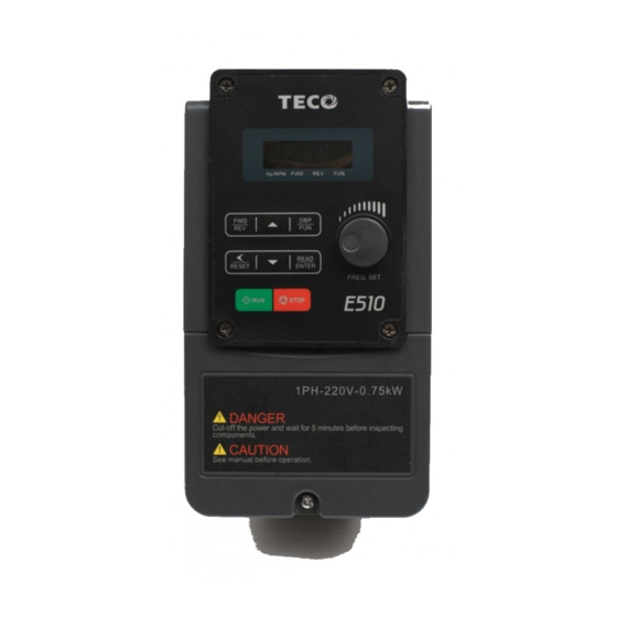
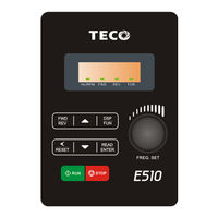
TECO e510 series Manuals
Manuals and User Guides for TECO e510 series. We have
5
TECO e510 series manuals available for free PDF download: Instruction Manual, Quick Start Manual
TECO e510 series Instruction Manual (223 pages)
Brand:
TECO
| Category:
Inverter
| Size: 9 MB
Table of Contents
Table of Contents
2
Preface
4
Before Power up
5
Chapter 1 Safety Precautions
5
During Power up
6
Before Operation
6
During Operation
6
Inverter Disposal
7
Nameplate Data
8
Model Identification
8
Chapter 2 Model Description
8
Standard Product Specification
9
IP66 / NEMA 4X Type
10
Installation Site
11
Tightening Torque for Terminals
11
Chapter 3 Environment & Installation
11
Electrical Ratings of Terminals
12
Installation Method
13
IP20 / NEMA 1 Standard Installation
13
Disassembly and Assembly Steps
19
Installation Space
31
Side by Side Installation
31
Single Unit Installation
31
Capacitor Reforming Guide after Long Storage
32
De-Rating Curves
32
Wiring Guidelines
33
Power Cables
33
Control Cable Selection and Wiring
33
Wiring and EMC Guidelines
34
Failure Liability
35
Considerations for Peripheral Equipment
36
Ground Connection
37
Inverter Exterior
38
IP20/NEMA 1 Exterior
38
IP66/NEMA 4X Exterior
43
Interior Layout
45
Warning Label
46
Product Specifications
47
General Specifications
49
Standard Wiring
51
Single Phase
51
Single/ Three Phase
52
Three Phase
53
Terminal Description
54
Description of Main Circuit Terminals
54
Control Circuit Terminal Description
56
JUMPER Function Description
57
Outline Dimensions
58
IP20/NEMA1 Dimensions
58
IP66/NEMA4X Dimensions
68
EMC Filter Disconnection
71
The Dimension and Installation of Operator Panel
72
Description of Dimension and Installation
72
Surface Installation Diagram
73
Description of Protective Cover
74
Keypad Description
75
Operator Panel Functions
75
Chapter 4 Software Index
75
Digital Display Description
76
Alpha Numerical Display Format
76
Digital Tube Lights Flashing Instructions
76
LED Display Examples
77
LED Status Description
77
Digital Display Setup
78
User Selectable Display Formats
78
Example of Keypad Operation
79
Increment/ Decrement Key Functions
79
Modifying Parameters
79
Operation Control
81
Programmable Parameter Groups
82
G Ro up 00- Basic Parameters
83
Motor Parameters
84
V/F Pattern Selection & Setup
84
External Digital Inputs and Relay Output Functions
85
Analog Signal Inputs / Analog Output
88
Preset Frequency Selections
89
Auto Run Function (Auto Sequencer)
90
Start/Stop Command Setup
93
Drive & Motor Protection Functions
94
Communication Function Setup
95
PID Function Setup
96
Performance Control Functions
97
Digital Display & Monitor Functions
98
Inspection & Maintenance Functions
99
PLC Setting Function
100
PLC Monitoring Function
101
Basic Parameters Group
102
Control Mode Selection
102
Main Run Command Source Selection
102
Parameter Function Description
102
Communication Frequency Command
103
Initial Frequency Selection
103
Initial Frequency Setpoint
103
Main and Alternative Frequency Command Modes
103
Jog Acceleration Time
104
Jog Deceleration Time
104
Jog Frequency
104
V/F Pattern Selections & Setup
105
Volts/Hz Patterns (V/F)
105
Slip Compensation Gain
107
V/F Mode Select
107
Volts/Hz Curve Modification (Torque Boost)
107
Up/Down Frequency Step
116
Multifunction Output Relay RY 1/RY 2 Functions
117
Multifunction Terminals S1~S6 Scan Time
117
S1~S5 Input Type Selection no & NC
117
Up/Down Keep Frequency Status after Stop Command
117
Frequency Reached Detection Range
118
Brake Engage Level
120
Brake Release Level
120
Preset Output Current Detection Delay Time
120
Preset Output Current Reached
120
Action to Set the Internal Multi-Function Input Terminals
121
Relay Output Status Type
121
Pre-Set Count 2
123
Output under Current Detection Delay Time
124
Analog Voltage & Current Input Selections AI1/AI2
125
External Analog Signal Input / Output Functions
125
Auto Run( Sequencer) Mode Selection
133
Auto Run(Auto Sequencer) Function
133
Momentary Power Loss and Restart
136
Number of Auto Restart Attempts
136
DC Injection Brake Time(Seconds)
137
Delay-ON Timer (Seconds)
137
Reset Mode Setting
137
Stopping Method
137
Kinetic Energy Back-Up Deceleration Time (KEB)
138
Main Circuit Low Voltage Detection
138
Power Loss Ride Trough Time
138
DC Injection Brake Level (Voltage Mode)
139
Protection Function Group
139
Trip Prevention Level During Acceleration
139
Trip Prevention Selection
139
AVR Function
140
Input Phase Loss Protection
140
OH over Heat Protection
140
Operation after Overload Protection Is Activated
140
Fire Mode (for Firmware below V1.1)
141
Over Torque Detection Control
141
Over Torque Protection Action
141
Assigned Communication Station Number
142
Communication Time-Out Operation Selection
142
Ground Fault Detection
142
RTU Code /ASCII Code Selection
142
PID Block Diagram
143
PID Feedback Value Selection
143
PID Target Value Selection
143
Derivative Time
144
Feedback Gain Coefficient
144
Feedback Loss Detection Mode
144
Proportional Gain
144
Integral Value Resets to Zero When Feedback Signal Equals the Target Value
145
Min PID Feedback Level
145
PID Wake up Function Delay Time
145
Carrier Frequency
146
Carrier Mode Selection
146
Prevention of Reverse Operation
146
Regeneration Prevention Function
147
Skip Frequency Range (±Frequency Band)
147
V/F Energy Saving Gain (VF)
147
Display Mode
149
Monitor Function Group
149
PID Feedback Display Format
149
Regeneration Prevention Voltage Level
149
Alarm Selections for Inverter Components Life Expectancy
150
Custom Units (Line Speed) Display Mode
150
Inputs and Output Logic Status Display (S1 to S6) & RY1~2
150
Drive Horsepower Code
151
Fault Log Display(Latest 3 Faults)
151
Frequency Command When Fault Appeared
151
Parameter Lock Key Code
152
Reset Drive to Factory Settings
152
Basic Instruction Set
155
Description for Special Register
155
Specification Description on Built-In PLC Function
155
Function of Basic Instructions
156
Application Instructions
157
Counter
157
Input under the Ladder Program Mode
158
Input under the Function Program Mode
158
Counter Mode 2
158
Timer
159
Timer Mode 2(ON-Delay Timer Mode2)
160
Timer Mode 3 (OFF-Delay Timer Mode1)
160
Timer Mode 4(OFF-Delay Timer Mode2)
161
Timer Mode 5 (FLASH Timer Mode 1)
161
Timer Mode 6(FLASH Timer Mode 2)
161
Timer Mode 7 (FLASH Timer Mode 3)
161
Analog Comparator
162
Running Instruction
163
ACC- DEC Module
164
MUL- DIV Module
165
Error Display and Corrective Action
166
Manual Reset and Auto-Reset
166
Chapter 5 Troubleshooting and Maintenance
166
Keypad Operation Error Instruction
168
Special Conditions
169
General Troubleshooting
170
Troubleshooting of the Inverter
171
Quick Troubleshooting of the Inverter
171
Troubleshooting for OC, OL Error Displays
173
Troubleshooting for OV, LV Error
174
Motor Not Running
175
Motor Overheating
176
Motor Runs Unbalanced
177
Routine and Periodic Inspection
178
Environment & Ground Connection
178
Terminals & Wiring
178
Voltage
178
Insulation Test Method
179
Maintenance
179
Maintenance Check List
179
Electromagnetic Contactor Circuit Breaker
180
Reactor Specifications
180
Chapter 6 Peripheral Components
180
Fuse Specification
181
Fuse Specification (UL Model Recommended)
181
Brake Resistor
182
Input Noise Filter
183
Instructions for UL
184
UL Standards
185
UL Standards Compliance
185
Main Circuit Terminal Wiring
185
Recommended Input Fuse Selection
186
Motor Overtemperature Protection
186
Field Wiring Terminals
186
Drive Short-Circuit Rating
186
Drive Motor Overload Protection
187
Motor Rated Current
187
Motor Overload Protection Selection
187
Overload Protection Settings
187
E510 Parameter Setting List
188
E510 MODBUS Communication Protocol
191
Communication Data Frame
191
Hardware Installation
191
Data Format ASCII MODE
191
CMS (Checksum and Time-Out Definition)
192
Node (Address)
192
Function Code
192
Crc Check
193
CRC Calculation Application Program
193
Error Code
194
Inverter Control
195
Command Data (Readable and Writable)
195
Monitor Data (Only for Reading)
195
Read the Data in the Holding Register [03H]
198
LOOP BACK Testing [08H]
199
Write Holding Register [06H]
200
Write in Several Holding Registers [10H]
201
Comparison List between Parameter and Register
203
PLC Communication Protocol
209
E510 Plc Memory Map
209
PLC Operation Instruction
210
Ladder Component Arrangement Mode
210
Code in the EEPROM/RAM Arrangement
211
Ladder Part
211
Function Block
216
Analog Compare
216
Operation Control Instruction
217
Add-Subtract
217
Multiply-Divide
217
PLC Run
218
Plc All Memory Clear
218
JN5-CM-USB Instruction Manual
219
Model Number and Specification
219
Model Number and Function Instruction
219
Dimensions of JN5-CM-USB
219
USB Interface Cable Pin Definition
220
RS232/USB at PC Side
220
RS485/RJ45 Pin Definition
220
RS485/RJ45 Connector at Inverter Side
220
510 Series Accessories Manual
221
Advertisement
TECO e510 series Instruction Manual (197 pages)
AC Inverter Drive Speed Controller
Brand:
TECO
| Category:
Controller
| Size: 8 MB
Table of Contents
Table of Contents
2
Chapter 0 Preface
4
Preface
4
Chapter 1 Safety Precautions
5
Before Power up
5
During Power up
6
Before Operation
6
During Operation
6
Inverter Disposal
7
Chapter 2 Part Number Definition
8
Model Part Number
8
Standard Product Specification
9
Chapter 3 Environment & Installation
10
Environment
10
Installation
11
Installation Method
11
Installation Space
24
Rating Curve
26
Wiring Guidelines
27
Power Cables
27
Control Cable Selection and Wiring
27
Wiring and EMC Guidelines
28
Failure Liability
29
Considerations for Peripheral Equipment
30
Ground Connection
31
Inverter Exterior
32
Specifications
38
Product Specifications
38
General Specifications
40
Standard Wiring
42
Single Phase
42
Single/ Three Phase
43
Three Phase
44
Terminal Description
45
Description of Main Circuit Terminals
45
Control Circuit Terminal Description
47
Outline Dimensions
48
EMC Filter Disconnection
58
Chapter 4 Software Index
59
Keypad Description
59
Operator Panel Function
59
Digital Display Description
60
Digital Display Setup
62
TECO e510 series Instruction Manual (116 pages)
200V Class 0.4-15KW, 400V Class 0.75-18.5KW
Brand:
TECO
| Category:
Inverter
| Size: 5 MB
Table of Contents
English
2
Table of Contents
2
Chapter 0 Preface
3
Preface
3
Chapter 1 Safety Precautions
4
Before Power up
4
During Power up
5
Before Operation
5
During Operation
5
Inverter Disposal
6
Chapter 2 Environment & Installation
7
Considerations for Peripheral Equipment
7
Specifications
8
Product Specifications
8
General Specifications
10
Standard Wiring
12
Single Phase
12
Single/Three Phase
13
Three Phase
14
Terminal Description
15
Description of Main Circuit Terminals
15
Control Circuit Terminal Description
16
Outline Dimensions
17
IP20/NEMA1 Dimensions
17
IP66/NEMA4X Dimensions
27
Chapter 3 Software Index
30
Keypad Description
30
Operator Panel Functions
30
Programmable Parameter Groups
31
Chapter 4 Troubleshooting and Maintenance
50
Error Display and Corrective Action
50
Manual Reset and Auto-Reset
50
Keypad Operation Error Instruction
52
Special Conditions
53
General Troubleshooting
54
漢語
55
第 0 章 前言
56
第 1 章 安全注意事項
57
送電前
57
送電中
58
運轉前
59
運轉中
60
檢查保養和更換時
61
第 2 章 周圍環境及安裝
62
週邊設備應用及注意事項
62
產品個別規格
63
產品共通規格
66
標準配線
67
端子說明
70
主迴路端子說明
70
控制迴路端子說明
70
外形尺寸圖
72
Ip20/Nema1 型產品外形尺寸
72
Ip66/Nema4X 型產品外形尺寸
82
第 3 章 軟體索引
85
面板功能說明
85
參數一覽表
86
第 4 章 異常診斷及保養
103
故障顯示及對策
103
手動復歸與自動復歸
103
按鍵操作錯誤
105
特殊情況說明
106
一般故障檢查方法
107
Advertisement
TECO e510 series Quick Start Manual (9 pages)
Brand:
TECO
| Category:
Inverter
| Size: 0 MB
Table of Contents
Quick Start Guide
1
Supply & Motor Connection
1
Apply Power to the Drive
2
Test Run from Keypad
2
Remote Speed Reference and Remote Run
3
Remote Mode Wiring. Speed Reference and Run Signals.
3
How to Alter Parameters
4
Basic Quick Start Parameter List
5
Control Modes & Auto Tune
6
Standard Wiring. Single Phase.
7
Single / Three Phase
8
TECO e510 series Quick Start Manual (9 pages)
Brand:
TECO
| Category:
Inverter
| Size: 0 MB
Advertisement
Related Products
TECO E510s Series
TECO E510-2P5-SH1F
TECO E510-201-SH1F
TECO E510-202-SH1F
TECO E510-203-SH1F
TECO E510-202-SH3
TECO E510-205-SH3
TECO E510-2P5-SH
TECO E510-208-SH3
TECO E510-210-SH3
TECO Categories
Inverter
Air Conditioner
Refrigerator
Chiller
Controller
More TECO Manuals
Login
Sign In
OR
Sign in with Facebook
Sign in with Google
Upload manual
Upload from disk
Upload from URL