
Related Manuals for TECO TP03 PLC


Summary of Contents for TECO TP03 PLC
- Page 1 TP03 PLC USER Manual TP03 Programmable Logic Controller TECO Electric & Machinery Co., Ltd.
-
Page 2: Table Of Contents
Contents Chapter 1 TP03 Introduction......................1-1 1 Model type description....................... 1-2 2 Product type ........................1-3 2.1 Basic module list ..................... 1-3 2.2 Expansion module list ..................... 1-6 2.3 Programming tool....................1-8 2.4 Accessory list ......................1-9 3 System configuration ....................... 1-10 4 OP07/08-TP03 cable (TP03-302MC) specification ............1-11 5 TP03-302PC cable specification .................. - Page 3 Chapter 3 Expansion unit specification..................3-1 1 Digital expansion unit ......................3-1 1.1 General specification....................3-1 1.2 Outline dimension ....................3-2 1.2.1 TP02 digital expansion unit I ............... 3-2 1.2.2 TP02 digital expansion unit II ..............3-2 1.2.3 TP03 digital expansion unit................3-2 1.3 Electric specification....................
- Page 4 Chapter 5 Wiring......................... 5-1 1 Wiring ..........................5-1 2 Basic unit wiring ........................ 5-2 2.1 Wiring power supply and specification..............5-2 2.1.1 Input wiring at power supply terminal ............5-2 2.1.2 Protection circuit: ..................5-3 2.2 Input wiring......................5-4 2.3 Output wiring ......................5-5 3 Expansion unit wiring ......................
- Page 5 Chapter 8 Special Relay ......................8-1 PC status (M) ........................8-1 Clock device(M) ......................8-1 Operation flags(M) ......................8-1 PC status(D)........................8-2 RTC(D) ..........................8-2 PC operation mode(M) ....................8-3 PC mode(D) ........................8-3 Step ladder flags (M)......................8-3 Step ladder flags (D) ......................8-4 Interruption disable(M)....................
- Page 6 Chapter 1 TP03 Introduction Chapter 1 TP03 Introduction..................1-1 1 Model type description ..................1-2 2 Product type ......................1-3 2.1 Basic module list..................1-3 2.2 Expansion module list................1-6 2.3 Programming tool ..................1-8 2.4 Accessory list .................... 1-9 3 System configuration ..................
-
Page 7: Chapter 1 Tp03 Introduction
Chapter 1 TP03 Introduction Chapter 1 TP03 Introduction TP03 is the latest generation of PLC developed by TECO. The high-speed and high-quality programmable logic controller has following features: High speed of executive time. Basic instructions: 0.31us / step (ANDB), 0.45us/step (LD) Large memory capacity: Program memory capacity: 4~8~16k steps. -
Page 8: Model Type Description
Chapter 1 TP03 Introduction 1 Model type description Main Module Type No. description TP03 - 20 M R - A Power supply A: AC 100 – 240V D: DC 24V Output R: Relay T: NPN transistor Function M: Standard H: Advanced S: Simple 14: 14 point Point... -
Page 9: Product Type
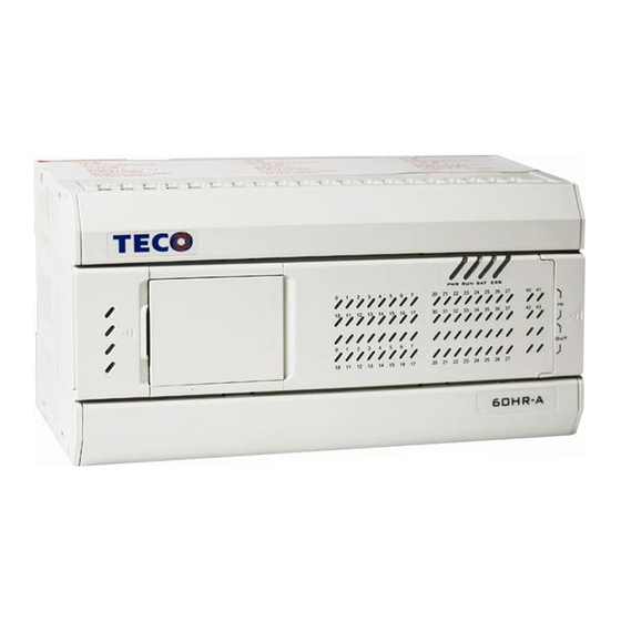
Chapter 1 TP03 Introduction 2 Product type 2.1 Basic module list Input point Output point User’s Rated Type 24vDC dimension current Input battery point type point type output current point TP03-14SR-A 116×92×64mm TP03-20SR-A 250mA See Fig3 TP03-26SR-A 177×92×64mm TP03-36SR-A See Fig4 TP03-20MR-A 85~264 TP03-30MR-A... - Page 10 Chapter 1 TP03 Introduction Fig 3 Fig 4 Nameplate description Softw are versi on Softw are versi on TP03 m odel TP03 m odel Model : TP03-60HR-A VX.X Model : TP03-60HR-A VX.X Pow er speci f i cati on Pow er speci f i cati on Power : 100~240VAC 50/60Hz Power : 100~240VAC 50/60Hz 50VAmax.
- Page 11 Chapter 1 TP03 Introduction Product profile and components introduction 1. Power supply terminals 2. RS485 port 3. Run/stop switch 4. 2 groups of potentiometer 5. PC/PDA communication port 6. Expansion port 7. Battery 8. Memory pack port 9. Input terminal block 10.
-
Page 12: Expansion Module List
Chapter 1 TP03 Introduction 2.2 Expansion module list Peripheral equipment Type Power Description Remark Source OP07 2 line LCD, timer and counter setting device Fig 5 OP08 24Vdc 2 line LCD, timer and counter setting device Fig 5 Profile referring figure: OP07/OP08 Fig 5 Expansion card... - Page 13 Chapter 1 TP03 Introduction Expansion module Power In/out Type No. Description dimension Remark Source point TP02-16EXD 16 / 0 16 points DC input TP02-16EYR 0 / 16 16 points relay output These 64 x 90 x TP02-16EYT 0 / 16 16 points transistor output modules are 76 mm...
-
Page 14: Programming Tool
TP03-PBUS (Fig 20) EN01 (Fig 21) 2.3 Programming tool Type No. Description Remark TP03-PC TP03 PLC PC software (Fig 23) The type no. for CD is TP03-CD06 (Fig 22) TP03-PDA TP03 PLC PDA software TP03-CD06 Disk (Fig 22) TP03-PC Disk (Fig 23) -
Page 15: Accessory List
Chapter 1 TP03 Introduction 2.4 Accessory list Built-in accessory description Type No. Remark Terminal connector (Fig 24) TP-200EC Install TP-200EC into the connector in the last Battery ( for 5years) expansion module in RS-485 built-in (H type only) Basic module Built-in order to form a I/O Standard cover for Expansion card... -
Page 16: System Configuration
Chapter 1 TP03 Introduction 3 System configuration Basic module Expansion cable TP02 expansion module TP03-40/60 TP-042EC (4cm) TP02-16EXD/TP02-16EYR/ TP-402EC(40cm) TP02-16EYT/TP02-16EMR/ TP02-4AD+/TP02-2DA+ Terminal connector TP-200EC TP02-32EMR TP03-20/30 Expansion cable TP03 expansion module TP03-304EC (4cm) +24V TP03-4TM / TP03-4RD/ TP03-2DA / TP03-3MA / TP03-340EC(40cm) TP03-8AD/ TP03-01SPS-A SHLD... -
Page 17: Op07/08-Tp03 Cable (Tp03-302Mc) Specification
Chapter 1 TP03 Introduction 4 OP07/08-TP03 cable (TP03-302MC) specification D-SUB 9 pin (Female) MINI DIN 8pin (Male) OP07/08 TP03 侧 (PC/PDA port) 1.8m TP03-302MC D-SUB/MINI DIN pin definition and internal connection: D-SUB 9pin(Female) MINI DIN 8pin(Male)(TP03 PG (PC/PDA) port) (OP07/08) definition definition RX +... -
Page 18: Tp03-302Pc Cable Specification
Chapter 1 TP03 Introduction 5 TP03-302PC cable specification D-SUB 9 pin (Female) MINI DIN 8pin (Male) TP03 (PC/PDA port) 1.8m TP03-302PC D-SUB/MINI DIN pin definition and internal connection: D-SUB 9pin(Female) MINI DIN 8pin(Male)(TP03 PG (PC/PDA) port) definition definition TX - RX - TX + RX +... -
Page 19: Tp03 Pc/Pda Port Connect With Hmi By Rs-422
Chapter 1 TP03 Introduction 6 TP03 PC/PDA port connect with HMI by RS-422 Take OP10 HMI as an example 0P10 TP03 PC/PDA TP03 PC/PDA port COM1 Port (Female) 7 TP03 terminal block INPUT TP03- OUTP 14SR-A COM0 COM1 +24V INPUT TP03- OUTP COMB... - Page 20 Chapter 1 TP03 Introduction +24V +24V Input TP03- 20MR-A C O M 0 C O M 2 Output 1 0 0 ~ 2 4 0 V A C C O M 1 12 14 16 +24V Input 11 13 15 TP03- 30MR-A C O M 0...
- Page 21 Chapter 1 TP03 Introduction C O M 0 C O M 2 Output 100~ 240VA C C O M 1 C O M 3 +24V Input TP03- 40HR-A 11 12 COM0 COM2 COM4 Output 100~240VAC COM1 COM3 +24V Input 11 13 41 43 TP03- 60HR-A...
- Page 22 Chapter 2 Basic Unit Specification Chapter 2 Basic Unit Specification................2-1 1 Function ..........................2-1 1.1 General specification....................2-1 1.2 AC type Power supply specification ............... 2-3 1.3 DC type Power supply specification ............... 2-3 1.4 General features for basic unit ................2-4 1.5 Environment specification ..................
-
Page 23: Chapter 2 Basic Unit Specification
Chapter 2 Basic Unit Specification Chapter 2 Basic Unit Specification 1 Function (-14S short for S type,as 14SR-A, 20SR-A, 26SR-A,36SR-A etc -20M short for: 20 points, M type, as TP03-20MR-A/TP03-20MT-A etc) -40H short for: 40 points, H type, as TP03-40HR-A/TP03-40HT-A/TP03-40HR-D etc.) 1.1 General specification Type -14S... - Page 24 Chapter 2 Basic Unit Specification Type -14S -20S -26S -36S -20M -20H -40H -60H Item Index register 32points: V000~V0015 / Z000~Z0015 Mark: N0~N7 ( 8points), pointer P0~P127 (128 Mark: N0~N7 ( 8points), pointer P0~P255 points), input interruption (256 points), input interruption pointer: pointer: I00~I30 (4points), Nest pointer I00~I50 (6points), timer interruption pointer:...
-
Page 25: Ac Type Power Supply Specification
Chapter 2 Basic Unit Specification Type -14S -20S -26S -36S -20M -20H -40H -60H Item When Y1 is set to count the output pulse, X3 can not be set as high speed counter. As for M type, if the frequency exceeds specified one, the output states are maybe not right. ※3: The basic units of 20/30 points can, through setting special registers D8256 &... -
Page 26: General Features For Basic Unit
Chapter 2 Basic Unit Specification 1.4 General features for basic unit Summary TP03 M type: 20 / 30 points Built-in Flash memory ( 8,000 Steps ) Retentive data with lithium battery Can expand 32 points and expand 2 x TP02-AD units and 1 x TP02-2DA unit or 1 TP03 AD unit and 1 DA unit. -
Page 27: Environment Specification
Chapter 2 Basic Unit Specification 1.5 Environment specification Item -14S -20S -26S -36S -20M -30M -20H -30H -40H -60H Operating Temperature 0 to 55 (32 to 131F) ( Operating ambient temperature ) ℃ Storage Temperature -25 to +70℃ Relative Humidity Level RH1, 30 to 95% (non-condensing) Pollution Degree 2 (IEC 60664) -
Page 28: Digital Input/Output
Chapter 2 Basic Unit Specification 2 Digital input/output 2.1 Digital input Electric specifications schematic diagram Input type DC (sink or source) Off→On Min. 15 VDC Voltage level On→Off Max. 9 VDC Input impedance 3.3k ohm 6.7~7.2mA @24VDC Current Off On: 1ms Response time On Off: 2.5 ms Insulation... - Page 29 Chapter 2 Basic Unit Specification With respect to expansion for 20 point basic unit, the input number for the first digital (analogue) expansion unit should be start from X20 (D8436) and so on. WhileWhile the output should be start from Y10 (D8381) and so on. With respect to expansion for 30 point basic unit, the input number for the first digital (analogue) expansion unit should be start from X20 (D8436) and so on.
-
Page 30: Communication Ports
Chapter 2 Basic Unit Specification 3 Communication ports 3.1 Communication ports position TP03 has three communication ports and see the left figure: <1>. PC/PDA communication port <2>. Expansion card TP3-232RS, TP3-485RS. <3>. RS485 communication port +24V COM0 COM2 100~240VAC COM1 COM3 RS485 port, only H type available. -
Page 31: Function Description For 3 Communication Port
Chapter 2 Basic Unit Specification 3.2 Function description for 3 communication port <1> <2> <3> PC/PDA RS485/ RS232 RS485 Description port expansion card port Upload or download the user program Program up/down to/from TP03 or update system ◎ load program. Available for PC/PDA monitoring the Modbus slave TP03. - Page 32 Chapter 2 Basic Unit Specification Communication setting for PC/PDA port (D8321) Item Description Data length (B0) 1: 8 bit Parity bit (B2,B1) (0, 0): no parity (0, 1): odd check (1, 1): even check Stop bit (B3) (0): 1bit (1): 2bits Baud rate (0, 1, 1, 1): 9.6 (1, 0, 0, 1): 38.4...
-
Page 33: Three Communication Ports Description
Chapter 2 Basic Unit Specification Note 5: It is necessary to add terminal resistor (120Ω,1/4W) when several PLCs are connected in the Net. Note6: The modified data for D8320 will take effect at the next scan time after communicaton finished. Note 7: The modified setting for D8120 will take effect at the next scan time after communicaton finished. - Page 34 Chapter 2 Basic Unit Specification Exception Code Under communication linking, the controller responses the Exception Code and send Function Code adding 80H (the highest bit is set to 1) to main system if there is error happened. Code Name Description The function code is illegal for slaves.
- Page 35 Chapter 2 Basic Unit Specification *1: High speed counter address mapping (C200~C255, 32-bit High speed counter) Word Register address Register value High byte Low byte 42C8H C200 Low byte of present value Low word High byte Low word Low byte 42C9H C200 High byte of present value High word High byte...
- Page 36 Chapter 2 Basic Unit Specification A. 01H read coil Function Code This function code is used to read from 1 to 2000 consecutive status of coils in a Function remote device. PLC PC(OK) PLC PC(ERROR) Slave Address Slave Address Slave Address Function Code Function Code Function Code...
- Page 37 Chapter 2 Basic Unit Specification B. 05H write a single coil Function Code This function code is used to write a single output to either ON or OFF in Function a remote device. PLC PC(OK) PLC PC(ERROR) Slave Address Slave Address Slave Address 01H Function Code Function Code...
- Page 38 Chapter 2 Basic Unit Specification D. 03H read register: Function Code This function code is used to read the contents of from 1 to 125 consecutive blocks of Function holding registers in a remote device. PLC PC(OK) PLC PC(ERROR) Slave Address Slave Address Slave Address Function Code...
- Page 39 Chapter 2 Basic Unit Specification E. 06H Write a single register Function Code Function This function code is used to write a single holding register in a remote device. PLC PC(OK) PLC PC(ERROR) Slave Address Slave Address Slave Address Function Code Function Code Function Code 86H High 40H...
- Page 40 Chapter 2 Basic Unit Specification G. 08H Diagnose: The function code 08 provides a series of tests for checking the communication system between a client (Master) device and a server (Slave), or for checking various internal error conditions within a server. Sub-function 00: Return Query Data Function Sub-function 0000...
- Page 41 Chapter 2 Basic Unit Specification b. Sub-function FF01: Write TP03 ID Function Sub-function FF01 Code Function Write TP03 ID PLC PC(OK) PLC PC(ERROR) Slave Address Slave Address 01H Slave Address 01H Function Function Code Function Code Code Exception High FFH High FFH Format Sub-function...
- Page 42 Chapter 2 Basic Unit Specification d. Sub-function FF03: Set RTC value Function Sub-function FF03 Code Function Set RTC value PLC PC(OK) PLC PC(ERROR) Slave Address 01 H Slave Address Slave Address 01H Function Code Function Code Function Code ECH Exception Sub- High Sub-...
-
Page 43: Data Link
Chapter 2 Basic Unit Specification 3.3.2 Data link TP03 master can communicate with as many as 15 TP03 slaves with the application instruction: DTLK. Here is the briefing about this function and as for more information, plese refer to Instruction Description F190 DTLK. Item Specification Communication... -
Page 44: Rs/Mbus Instruction
Chapter 2 Basic Unit Specification 3.3.4 RS/MBUS instruction Here is the briefing about this function and as for more information, plese refer to Instruction Description F80 (RS) and F87 (MBUS). Application Instruction F80: RS F87: MBUS S: sending address m: data length(0~255) D: receiving address n : receiving data length(0~255) K: port selection, range: 0~1 . - Page 45 Chapter 2 Basic Unit Specification Wiring for built-in RS485 port or RS485 expansion card. Linking with controller DATA LINK & REMOTE I/O communication. Note 1: SHL terminal should be 3 class ground or the production will be interrupted to error operation because of noise.
-
Page 46: High Speed Counter
Chapter 2 Basic Unit Specification 4 High speed counter 4.1 General characteristic of high speed counter Input requirements: A. the duty circle for the input form should be 1:1; B. Low voltage level should be less than 9V. C. The respnding frequency of the high speed counter differs from high /low voltage level. Frequencty Input teminal High voltage level... - Page 47 Chapter 2 Basic Unit Specification Reading the table: 1phase 1 input counting: X000 input: corresponding to C235 (U/D) which has no interruption reset and set function Or corresponding to C241 (U/D) which can be interruption reset by X001 and has no interruption set function.
-
Page 48: Function
Chapter 2 Basic Unit Specification 4.3 Function The high speed counter operates differently if the input is not same. Refer to the former table for fore information about the operation. The Set and Reset of the high speed counter, having nothing to do with PLC scan time, is controlled by interruption pointer. -
Page 49: Application Example For 1 Phase High Speed Counter
Chapter 2 Basic Unit Specification 4.4 Application example for 1 phase high speed counter 4.4.1 1 Phase 1 input X010 OFF: up counting; X010 OFF: Down counting If X011 is enabled, C235 will be reset (RST). When X012 is ON, C235 will count input X000. X010 controls C235 up/down counting. -
Page 50: Phase 2 Input
Chapter 2 Basic Unit Specification 4.4.2 1 Phase 2 input X012 is ON: C246 will operate up counting when Input X000 is OFF ON, while Down counting when X001 is OFF ON. X012 is ON: C249 will start to operate up counting for X001, down counting for X000 when X005 is ON. -
Page 51: Action Of 2 Phase Input Signal
Chapter 2 Basic Unit Specification 4.5.2 Action of 2 phase input signal 2 phase encoder can produce A phase and B phase with 90° phase difference to A phase. Such high speed counter can automatically up count or down count. The following indicates operation of 2 phase counter. -
Page 52: Common Consideration:
Chapter 2 Basic Unit Specification 4.8 Common consideration: The enabling terminal for high speed counters should be always ON. It is recommended to use contact without mechanical delay for high speed counter enabling device.The vibration of the analog switch would result in high speed counting error. Thusly, the analog switch can not be used as an enable device for high speed counter. -
Page 53: Interruption Input
Chapter 2 Basic Unit Specification 5 Interruption Input The input X000~X005 can be set to do interruption. Basic specification Type -14S -20S -26S -36S -20M -30M -20H -30H -40H -60H Item Input X000~X003 X000~X005 Pulse width 50us min. 5us min. Interruption definition: I x 0 x 0: Falling edge interruption... -
Page 54: Pulse Output
Chapter 2 Basic Unit Specification 6 Pulse output Basic specification Type -20MT -30MT -20HT -30HT -40HT -60HT Item Pulse output 2 Points Y0/Y1 with acceleration/deceleration, without interpolation PWM output 2 Points Y0/Y Frequency 1KHz max. 100KHz max. Voltage range 12 ~ 24VDC Current range 10 mA ~ 300mA Output type... -
Page 55: Built-In Memory And Memory Card (Tp03-1Me)
Chapter 2 Basic Unit Specification 8 Built-in memory and memory card (TP03-1ME) Built-in memory Type Saving content Saving place 1. User program (20/30 type: 0~8K, 40/60type: 0~16K) Built-in flash Memory 2. File register (D2000~D7999, 6K) memory (power fail In total: 16K have no impact on program 3. -
Page 56: Password
Chapter 2 Basic Unit Specification 9 Password Password set through TP3-PC or TP3-PDA can prevent the program from illegal upload or download. The password has 3 levels of protection with a letter 1, 2 or 3 in the head. Function Setting Description 1. - Page 57 Chapter 2 Basic Unit Specification 11 RTC Type -20M -30M -20H -30H -40H -60H Item Built-in: Second(D8013), Minute(D8014), Hour(D8015),Day(D8016), Month(D8017), Year(D8018), Register Week(D8019) With 30s offset F160 TCMP: timing data compare F161 TZCP: timing area data compare Special application F162 TADD: timing data add instruction (refer to F163 TSUB: timing data subtract the Instruction...
-
Page 58: Potentiometer
Chapter 2 Basic Unit Specification 12 Potentiometer TP03 has built-in standard analog potentiometer with corresponding data (0~1023) saved in hereinafter DATA register. Such potentiometer could be set as the indirect set value for analog timer, which is called analog potentiometer timer. As for the above example, the input value can be multified with the application instruction F22. -
Page 59: Battery
Chapter 2 Basic Unit Specification 13 Battery Electric specification Item Description Part number BT-CR2450-CB-01 Voltage Capacity 600mA-HR Lifespan 5 Year 1. For use Do not charge the battery; do not short circuit the batter; use the battery only for the specified equipment; insert the battery in right polarity position;... - Page 60 Chapter 3 Expansion unit specification Chapter 3 Expansion unit specification ..............3-1 1 Digital expansion unit ..................3-1 1.1 General specification ................3-1 1.2 Outline dimension.................. 3-2 1.2.1 TP02 digital expansion unit I............3-2 1.2.2 TP02 digital expansion unit II............3-2 1.2.3 TP03 digital expansion unit ............
-
Page 61: Chapter 3 Expansion Unit Specification
Chapter 3 Expansion unit specification Chapter 3 Expansion unit specification 1 Digital expansion unit 1.1 General specification Type TP02 TP02 TP02 TP02 TP02 TP03 TP03 TP03 TP03 TP03 Item -16EXD -16EYR -16EYT -16EMR -32EMR -16EMR -16EMT -16EYR -16EYT -16EXD Expansion unit Brick type outline Input point... -
Page 62: Outline Dimension
Chapter 3 Expansion unit specification 1.2 Outline dimension 1.2.1 TP02 digital expansion unit I 1.2.2 TP02 digital expansion unit II COMA COMA COMA COMA 9 11 COMc COMd COMb COMe 1.2.3 TP03 digital expansion unit expansion unit... -
Page 63: Electric Specification
Chapter 3 Expansion unit specification 1.3 Electric specification 1.3.1 TP02-16EXD Specification Item specification Outline figure Input point Upside terminal block Output point COMA Input voltage DC24V +10%~-20% Input current 4.8mA @24VDC COMA Input impedance 5 kΩ Typ. ON voltage/current level >... -
Page 64: Tp02-16Eyr Specification
Chapter 3 Expansion unit specification 1.3.2 TP02-16EYR Specification Item Specification Outline figure Input point Upside terminal block Output point COMA Voltage AC250V/DC30V 2A/1 COMB Current point ;5A/1common Type Relay Mechanical lifespan 20,000,000 times Output Electric lifespan 150,000 times @ 3A Response time Below 10ms Min load... -
Page 65: Tp02-16Eyt Specification
Chapter 3 Expansion unit specification 1.3.3 TP02-16EYT specification Item Specification Outline figure Input point Upside terminal block Output point C(-).A DC4v~DC27V Voltage C(-).B Current 0.3A/1point; 1A/1 common Type Transistor NPN Output Response time Below 1ms Output LED lit when output ON. indicator Insulation Photo-coupling insulation... -
Page 66: Tp02-16Emr Specification
Chapter 3 Expansion unit specification 1.3.4 TP02-16EMR Specification Item Specification Outline figure Input point Upside terminal block Output point COMA Voltage AC250V/DC30V Current 2A/1 Point; 5A/1 common COMA type Relay Mechanical 20,000,000 times lifespan Output Electric lifespan 150,000 times @ 3A Responding time Below 10ms Min load... -
Page 67: Tp02-32Emr Specification
Chapter 3 Expansion unit specification 1.3.5 TP02-32EMR Specification Item Specification Outline figure Input point Upside terminal block Output point Voltage AC250V/DC30V 11 13 15 COMA COMA 2A/1 COMA COMA Current point ;5A/1common Type Relay Mechanical 20,000,000 times lifespan Output Electric lifespan 150,000 times @ 3A Responding time Below 10ms... -
Page 68: Tp03-16Emr Specification
Chapter 3 Expansion unit specification 1.3.6 TP03-16EMR Specification Item Specification Outline figure Input point COMA Output point Voltage AC250V/DC30V COMA 2A/1 point; Current 5A/1 common terminal Type Relay PWR OE Mechanical lifespan 20,000,000 times Output Electric lifespan 100,000 times @ 3A Responding time Minimal Load 1 mA @ 5vDC... -
Page 69: Tp03-16Emt Specification
Chapter 3 Expansion unit specification 1.3.7 TP03-16EMT Specification Item Specification Outline figure Input point COMA Output point Voltage DC 4V~30V COMA 0.3A/1 point; Current 1.2A/1 common terminal Output Type NPN transistor PWR OE Responding time < 1ms Output indicator LED lit when output ON Insulation method Relay DC24V +10%~-20%... -
Page 70: Tp03-16Eyr Specification
Chapter 3 Expansion unit specification 1.3.8 TP03-16EYR Specification Item Specification Outline figure Input point COMA Output point COMB Voltage AC250V/DC30V 2A/1 point; Current 5A/1 common terminal Type Relay Mechanical lifespan 20,000,000 times Output Electric lifespan 100,000 times @ 3A Responding time COMC Minimal Load 1 mA @ 5vDC... -
Page 71: Tp03-16Eyt Specification
Chapter 3 Expansion unit specification 1.3.9 TP03-16EYT Specification Item Specification Outline figure Input point COMA Output point COMB Voltage DC 4V~30V 0.3A/1 point; Current 1.2A/1 common terminal Output Type NPN transistor Responding time < 1ms Output indicator LED lit when output ON Insulation method Relay COMC... -
Page 72: Tp03-16Exd Specification
Chapter 3 Expansion unit specification 1.3.10 TP03-16EXD Specification Item Specification Outline figure Input point Output point COMA DC24V +10%~-20% Voltage COMA Current 7mA @24VDC Impedance 3kΩ Type. ON level Above 15Vdc (4.2mA) Input OFF level Below 9 Vdc (2.5mA) Responding time 10ms Indicator LED lit when input ON... -
Page 73: Analogue Expansion Unit
Chapter 3 Expansion unit specification 2 Analogue expansion unit 2.1 Introduction 2.1.1 Brief Analog expansion unit for input: TP02-4AD+,TP03-4AD,T0P3-8AD,TP03-4RD, TP03-4TM …etc. Analog expansion unit for output: TP02-2DA+,TP03-2DA …etc. Analog expansion unit for both input and output: TP03-3MA …etc. Note : TP03-8AD,TP03-2DA,TP03-3MA only can be used for TP03 M/H type which version over V1.5 or for TP03 SR type which version over V1.2. -
Page 74: Data Register And Channel Of Analog Expansion Module
Chapter 3 Expansion unit specification Example 2: Max basic system configuration Max configuration includes several common I/O expansion units (max 256 points) + (TP02-4AD)*1+(TP03-8AD)*7+(TP02-2DA)*1+(TP03-2DA)*4 Basic unit(60HR)(TP03-8AD)*7 (TP03-2DA)*4 (TP02-32EMR)*6 (TP02-4AD+) (TP02-2DA+) Note: Among all the expansion units for TP03 basic unit, the TP02 expansion should be installed after TP03 expansion unit, including I/O module, AD and DA module. -
Page 75: Setting The System Memory
Chapter 3 Expansion unit specification 2.1.3 Setting the system memory Please set the system memory in advance, before try-run the connected units. Setting TP02 TP03 EXTEND MODULE System memory Remarks EXTEND ault 20/30 point MODULE 40/60 point And S type ONLY Set the number of Modules... - Page 76 Chapter 3 Expansion unit specification AD CH4=0,AD mode is disabled. For example: DA mode D8278=H3210 DA CH5=0,DA mode is disabled; DA CH6=1,0~10V Voltage output mode (0~4000); DA CH7=2,0~20m ACurrent output mode (0~2000); DA CH8=3,4~20mA Current output mode or 1~5V Voltage output mode (0~2000). Software filter for analog input expansion unit (Mode 1): refresh data in each scan time.
-
Page 77: General Specification For Analog Expansion Unit
Chapter 3 Expansion unit specification 2.2 General Specification for analog expansion unit Item Analog expansion unit Storage temperature -25~70 ℃ Ambient 0~55 ℃ temperature Humidity range 5~90%HR(Non condense) Installation Install directly or DIN rail Ground Less than100 ohm Insulation system Photo-coupling isolation Insulation 10M Ω... -
Page 78: Wiring For Analog Expansion Module
Chapter 3 Expansion unit specification 2.4 Wiring for analog expansion module Wiring figure of Input (A/D) analog expansion module: 1. The cable for analog input should be standard isolated twisted cable, routed away power line and other line which will interrupt others. It is recommended that the cable should be less that 3m in length. - Page 79 Chapter 3 Expansion unit specification expansion unit 3-19...
-
Page 80: Electric Specification
Chapter 3 Expansion unit specification 2.5 Electric Specification 2.5.1 TP02-4AD+ Specification Specification Item Voltage Current 0V~10V or 1V~5V , 0mA~20mA or 4mA~20mA , Analog input range Input impedance 30KΩ Input impedance 250Ω 0000(0V)~4000(10V) or 0000(0mA)~2000(20mA)or Data range 0000(1V)~2000(5V) 0000(4mA)~2000(20mA) Resolution 2.5 mV 10 μA Accuracy... -
Page 81: Tp03-8Ad Specification
Chapter 3 Expansion unit specification 2.5.2 TP03-8AD Specification Specification Item Voltage Current 0V~10V or 1V~5V , 0mA~20mA or 4mA~20mA , Analog input range Input impedance 30KΩ Input impedance 250Ω 0000(0V)~4000(10V)or 0000(0mA)~2000(20mA)or Data range 0000(1V)~2000(5V) 0000(4mA)~2000(20mA) Resolution 2.5 mV 10 μA Accuracy ±1% or less(at 25 ±1%or less(at 0~55... -
Page 82: Tp03-4Rd Specification
Chapter 3 Expansion unit specification 2.5.3 TP03-4RD Specification Item Specification Temperature range Pt100: -100 ~600 ( ℃ 60Ω~330Ω) ℃ Digital output 0350~4000(-100 ~600 ) ℃ ℃ Resolution 2.5 mV Accuracy ±0.5% FSR (-100 ~600 ℃ ℃) Sensor type RTD; α=0.00385;2 or 3 wires Transmit speed 1scan time/ 4 Channel A0 B0... -
Page 83: Tp03-4Tm Specification
Chapter 3 Expansion unit specification 2.5.4 TP03-4TM Specification Specification Item J-type K-type Temperature range 0℃~700℃ 0℃~1200℃ Digital output 0000~4000 0000~4000 Resolution 2.5 mV Accuracy ±0.5% FSR (0℃~1200 ) ℃ Sensor type Thermocouple J-type /K-type Transmit speed 1scan time/ 4 Channel Thermistor (J,K type) signal TC0+~TC3+ input+ terminal... -
Page 84: Tp02-2Da+ Specification
Chapter 3 Expansion unit specification 2.5.5 TP02-2DA+ Specification Specification Item Voltage Current 0V~10V or 1V~5V, external impendence 0mA~20mA or 4mA~20Ma, Principle Analog output range should be less than 500Ω figure 500Ω. 0000(0V)~4000(10V) or 0000(0mA)~2000(20mA) or Data range 0000(1V)~2000(5V) 0000(4mA)~2000(20mA) Resolution 2.5 mV 10 μA Accuracy... -
Page 85: Tp03-2Da Specification
Chapter 3 Expansion unit specification 2.5.6 TP03-2DA Specification Specification Item Voltage Current I0-C0, 0mA~20mA or V0-C0,V1-C1: 0V~10V or 1V~5V I1-C1: 4mA~20mA. ±V0-C2, C1-C3: -10V~ +10V. Analog output range external impendence should be more than external impendence should be 500Ω less than 500Ω. 0000(0V) ~ 4000(10V) or 0000(0mA) ~ 2000(20mA) or Data range... -
Page 86: Tp03-3Ma Specification
Chapter 3 Expansion unit specification 2.5.7 TP03-3MA Specification Specification Item Voltage Current Vin0-COM0 0V~10V or Iin0-COM0 0mA~20mA or Input Vin1-COM1 1V~5V Iin1-COM1 4mA~20mA , range Input Input impedance 30KΩ Input impedance 250Ω Data 0000(0V)~4000(10V) or 0000(0mA)~2000(20mA) or range 0000(1V)~2000(5V) 0000(4mA)~2000(20mA) Vout -COM 0V~10V or 1V~5V Iout -COM... - Page 87 Chapter 3 Expansion unit specification Input circuit Output circuit Principle figure expansion unit 3-27...
-
Page 88: How Many Expansion Unit Can Be Connected To Base Unit
Chapter 3 Expansion unit specification 3 How many expansion unit can be connected to base unit The maximal number of expansion unit than can be connected to base unit is related to the specification about base unit and the power consumed by expansion unit Next four will be think about. -
Page 89: For Example
Chapter 3 Expansion unit specification 3.3 For example There is application which needs one TP03-60HT-A and four TP03-16EMR and one TP03-8AD.There are thirty relay output at same time. We will calculate the consumption of power to detect if it’s suitable for TP03. The first step,calculate 5v current (refer to Table 3.2.2) unit 5V current(mA)... -
Page 90: Chapter4 Dimension And Installation
Chapter4 Dimension and installation Chapter4 Dimension and installation................. 4-1 1 Outline dimension.................... 4-1 1.1 Basic unit ....................4-1 1.2 TP02 expansion unit ................4-2 1.3 TP03 expansion unit and power unit ............. 4-3 1.4 TP03 communication unit..............4-3 2 Installation......................4-5 2.1 Ambient environment ................ -
Page 91: Outline Dimension
Chapter4 Dimension and installation Chapter4 Dimension and installation 1 Outline dimension 1.1 Basic unit TP03-14SR-A 14/20 TP03-20SR-A TP03-26SR-A 26/36 TP03-36SR-A TP03-20MR-A / TP03-20HR-A / TP03-20MT-A / TP03-20HT-A 20/30 TP03-30MR-A / TP03-30HR-A / TP03-30MT-A / TP03-30HT-A Outline dimension... -
Page 92: Tp02 Expansion Unit
Chapter4 Dimension and installation TP03-40HR-A / TP03-40HT-A / TP03-40HR-D 40/60 TP03-60HR-A / TP03-60HT-A / TP03-60HR-D 1.2 TP02 expansion unit TP02-16EXD/ TP02-16EYR/ TP02-16EYT/ TP02-16EMR/ TP02-4AD+/ TP02-2DA+ TP02-32EMR 11 13 15 COMA COMA 10 12 COMA COMA COMc COMd 10 12 13 15 COMb COMe Outline dimension... -
Page 93: Tp03 Expansion Unit And Power Unit
Chapter4 Dimension and installation 1.3 TP03 expansion unit and power unit TP03-16EMR-A/TP03-16EMT/TP03-16EYR/TP03-16EYT/TP03-16EXD TP03-2DA/ TP03-3MA/ TP03-8AD/ TP03-4TM/TP03-4RD TP03-01SPS-A TP03-16EMR/TP03-16EYR TP03-4TM/ TP03-2DA/ TP03-3MA/ /TP03-16EXD/TP03-16EMT TP03-8AD/TP03-01SPS /TP03-16EYT 1.4 TP03 communication unit PBUS DNET SG2- PROFI BUS- DP TCP-IP Outline dimension... -
Page 94: Installation
Chapter4 Dimension and installation 2 Installation 2.1 Ambient environment TP03 PLC should be installed in the closed-type distributor with sufficient space for dissipation (refer to following figure) in order to keep the PLC in good condition. TP03 >50cm >50cm TP03 PLC... -
Page 95: Directly Installation
Chapter4 Dimension and installation 2.2.1 Directly installation Please use M4 ×15mm or bigger screws to fix the PLC in the distributors. When the expansion cable (4cm) is used, please refer to 6.1 for installation dimension and use M4 screws to fix the units. Basic unit TP03-20□□-□/ TP03-30□□-□... - Page 96 Chapter4 Dimension and installation 11 13 COMA COMA 10 12 COMA COMA COMc COMd 10 12 13 15 COMb COMe The following figure indicates dimension for installation holes when expansion cable (4cm) is used. And the fixing screw should be M4. Installation...
-
Page 97: Din Rail Installation
Chapter4 Dimension and installation 2.2.2 DIN Rail installation Please user Din rail with width 35mm and mounting clamp for installing PLC installing uninstalling Firstly, place the groove at the back of modules Pull out the retractable mounting feet. Then right on the upper edge of Din rail. Then push rotate the mould at the bottom to outside. - Page 98 Chapter4 Dimension and installation Example 2: COMA COMA 9 11 COMA COMA Example 3: expansion 扩充 COMA COMA 9 11 COMA COMA Before installing, please make sure the power is off. Installing step for expansion cable and terminal connector: (1) Open the expansion connector cover; (2) Withdraw the termination connector originally installed the basic module at right side.
- Page 99 Chapter 5 Wiring Chapter 5 Wiring......................5-1 1 Wiring ......................5-1 2 Basic unit wiring ....................5-2 2.1 Wiring power supply and specification ..........5-2 2.1.1 Input wiring at power supply terminal......... 5-2 2.1.2 Protection circuit:................. 5-3 2.2 Input wiring.................... 5-4 2.3 Output wiring ..................
-
Page 100: Wiring
Chapter 5 Wiring Chapter 5 Wiring 1 Wiring Please use the input and output signal wire with O or Y Ends (see figure below). The torsion torque should be 5~8kg-cm (4.3~6.9 in-lbs). m m (M ax) m m (M ax) m m (M i n)... -
Page 101: Basic Unit Wiring
2.1 Wiring power supply and specification 2.1.1 Input wiring at power supply terminal TP03 PLC is classified into DC and AC type. Please pay attention to following items. For AC type: AC power range (100VAC~240VAC). Connect the power supply with L N terminal on PLC. -
Page 102: Protection Circuit
①AC power supply load which can prevent the system from instability ②Fuse for protection circuit (3A) when in frequently ON/OFF the power. ③Power indicator ⑥TP03 PLC Body ④Emergent stop switch ⑦ Third class ground To cut off the power in emergent Power supply ⑧... -
Page 103: Input Wiring
Chapter 5 Wiring 2.2 Input wiring Input signal has two methods to be wired for DC input: SINK and SOURCE mode. ◎ Sink = current inputs share the common Source = Current outputs share the common Wiring ◎ A. SINK mode Input equivalent circuit. -
Page 104: Output Wiring
Chapter 5 Wiring 2.3 Output wiring 1. PLC Output has two types: relay and Load transistor. Please refer to chapter 2 for electric specification related to it. 2. Operation indicator: When the output is ON, the corresponding indicator will Relay output be lit. - Page 105 Chapter 5 Wiring Over load capacity for output terminal Each output terminal has the overload capacity of 2 times of rated current/ 5Min and the common terminal has 1.5 times of rated current/ 2Min. If that exceeds limited range, the terminals will be fault or even the internal circuit will be dangerously burned.
-
Page 106: Expansion Unit Wiring
Chapter 5 Wiring 3 Expansion unit wiring 3.1 Input wiring for expansion unit TP02-16EXD COMA COMB COMA COMB TP02-16EMR TP02-32EMR 13 15 COMA COMA COMA 2 4 6 COMA COMA COMA TP03-16EXD COMA COMB COMA COMB TP03-16EMR/TP03-16EMT COMA COMA Wiring consideration... -
Page 107: Output Wiring For Expansion Unit
Chapter 5 Wiring 3.2 Output wiring for expansion unit TP02-16EYR / TP02-16EYT COMC COMC COMD COMD TP02-16EMR TP02-32EMR COMC C O M c C O M d C O M b C O M e COMD TP03-16EYR/ TP03-16EYT COMC COMA COMD COMB TP03-16EMR/TP03-16EMT... -
Page 108: Wiring Consideration
Chapter 5 Wiring 4 Wiring consideration 4.1 Wiring consideration for Input power terminal 4.1.1 When Built in DC24V power supply share Common terminal with External power Note: External DC2V + terminal can connect with the COM on the PLC, while – terminal must be separated. -
Page 109: Wiring Consideration For Different Input Devices (Sensor/ Switch
Chapter 5 Wiring 4.2.1 Wiring consideration for different Input devices (sensor/ switch…) DC input Example . 1 DC 2 wires type (proximity sensor): Example 2 . Contact output type Example 3 . NPN open collector type Example . 4 PNP open collector type Example 5 .... -
Page 110: Leakage Current Of Input Component
Chapter 5 Wiring 4.2.2 Leakage current of Input component AS for the following example, when there is leakage current as signal OFF, and larger than the module OFF current, the module can not OFF or Onise margin will not work as module is OFF. <Reference >... -
Page 111: Output Terminal Wiring Consideration
Chapter 5 Wiring 4.3 Output terminal wiring consideration: 4.3.1 Surge current from Indicator load: When the incandescent lamp is turned on, there will be a surge current 10~20 times larger than normal value lasting some 10ms. It is recommended to add a shunt resistor or a bleeding resistor to reduce that surge. -
Page 112: Driving A Light Load
Y0 and Y1 share one common terminal COM0,the COM0 and USER 0V are connected internally in TP03 PLC. Be sure not to connect USER 24V and COM0,the other COM and USER 0V are not connected internally in TP03 PLC. -
Page 113: Solving Noise Problem
Chapter 5 Wiring 5 Solving noise problem The wiring between PLC and external device will result in external noise affecting PLC system. Here is the noise immunity resolution for different application. Grounding PLC should be separately grounded. Particularly, it should not be grounded together with other heavy load (including inverter or motor). -
Page 114: Solving Thunder Stroke Problem
Chapter 5 Wiring TP03 Isolation transformer AC Power source AC Power input The closer the isolation transformer located to PLC input, the better. AC power wire should be twisted wire. The capacity of isolation transformer should be more than 120% consumption capacity of PLC, or the voltage at primary side of transformer would larger than rated one that will undermine safety. -
Page 115: Anti-Noise For Expansion Cable
Chapter 5 Wiring The special type 3 ground (resistance less than 10ohm) must be installed separately with PLC ground. Applying underground pipeline may isolate the voltage induced from the air. (Under thunderbolt, the voltage induced from the air may be exceeding 24 VDC.) The pipeline should be buried underground in depth at least 60 cm. - Page 116 Trial Run Chapter 6 Trial Run.....................6-1 1 Trial run ......................6-1 1.1 Before Trial run..................6-1 1.2 Trial run step ...................6-2 2 Maintenance and Inspection ................6-3 2.1 Periodical inspection................6-3 2.1.1 General items: ................6-3 2.1.2 Basic unit: ..................6-3 2.1.3 Expansion units:................6-3 3 Troubleshooting ....................6-4 3.1 LED indicator status ................6-4 3.2 Presumption of troubleshooting procedure..........6-4 3.3 Preparation for troubleshooting ..............6-4...
-
Page 117: Chapter 6 Trial Run
Trial Run Chapter 6 Trial Run 1 Trial run 1.1 Before Trial run When TP03 installing and wiring finished, check the following points before Power ON. ● Is the TP02 expansion module wired in the end? ● Is the product type right? 1 Check installation condition ●... -
Page 118: Trial Run Step
Trial Run 1.2 Trial run step Run PDA06/PC06 to design program on PDA/PC including Setting system memory (D8321) 1 Write program Design program Save the designed program 2 Link PDA/PC with PLC Whether the POWER indicator is ON? Whether the RUN indicator is lit. Please switch the RUN/STOP to STOP. -
Page 119: Maintenance And Inspection
Trial Run 2 Maintenance and Inspection 2.1 Periodical inspection Please refer to following tables to periodically inspect TP03 in order to keep it in best operation condition. 2.1.1 General items: Inspection item Check up Criterion Remark Ambient temperature Refer to installation precaution 0~55℃... -
Page 120: Troubleshooting
Trial Run 3 Troubleshooting Please check the indicators on basic units as error occurs. And do troubleshooting according to different conditions. 3.1 LED indicator status M,H type Description Troubleshooting procedure – 2 Power is OFF Self-diagnosis detects error that program does Troubleshooting procedure –... -
Page 121: Check The Following Again
Trial Run c. Spare units Prepare necessary replacement for faulty units d. System memory setting recorder and I/O relay assignment lists. Please prepare ‘system memory setting recorder’ and ‘I/O relay assignment lists’. 3.4 Check the following again Power indicator The red indicator for POWER will be on as the main unit/ expansion unit is supplied with power. -
Page 122: Troubleshooting Procedure
Trial Run 3.5 Troubleshooting procedure 3.5.1 Troubleshooting procedure - 1 M register D register Continue to operate Function Error code description Error code :200x: Expansion card not adapt to x: card install in fact 1:TP03-6AV 2:TP03-485RS Expansion card 8060 8060 3:TP03-232RS error 4:TP03-2AI... -
Page 123: Troubleshooting Procedure - 2
Trial Run M register D register Continue to operate Function Error code description Error code 6705: address error 6706: parameter error 6730: sampling time out of range(Ts<0) 6732: PID input filter out of range 6733: PID proportional gain out of range (Kp) 6734: PID integral time const out of range.(TI) -
Page 124: Troubleshooting Procedure - 3
Trial Run 3.5.3 Troubleshooting procedure - 3 3.5.4 Troubleshooting procedure - 4 This procedure is designed for input signal error which can not be detected by CPU self-diagnose. Error example: None of input and output terminals on basic unit and expansion unit can set ON. Certain input can not be set ON/OFF. -
Page 125: Troubleshooting Procedure - 5
Trial Run 3.5.5 Troubleshooting procedure - 5 This procedure is designed for output signal error which can not be detected by CPU self-diagnose. Error example: None of output terminals on a certain basic unit or expansion unit can set ON. (Normally, the fuse for output is melted.) Certain output can not be set ON/OFF. -
Page 126: Chapter 7 Instruction List
Instruction list Chapter 7 Instruction List ..................7-1 1 Basic sequential instruction ................7-1 2 Step instruction :STL, RET................7-2 3 Application instruction list................7-3... - Page 127 Instruction list Chapter 7 Instruction List 1 Basic sequential instruction Mnemonic Function Circuit Step Initial logical operation contact [LD] type NO (normally open) Initial logical operation contact type [LDI] NC (normally closed) Serial connection of NO (normally [AND] open) contacts Serial connection of NC (normally [ANI] closed) contacts...
-
Page 128: Step Instruction :Stl, Ret
Instruction list Mnemonic Function Circuit Step [INV] Inverse Denotes the start of a master control [MC] block Denotes the end of a master control [MCR] block [NOP] No operation [END] Program End [STL] Step ladder [RET] Step ladder return [PLS] Rising edge pulse Falling / trailing edge pulse [PLF]... -
Page 129: Application Instruction List
Instruction list 3 Application instruction list Application instruction 16/32 Step Type Instruction type Mnemon function 32bit 16bit S Conditional jump √ —— ○ ○ ○ CALL Call subroutine √ —— ○ ○ ○ SRET Subroutine return —— ○ ○ ○ IRET Interrupt return ——... - Page 130 Instruction list Application instruction 16/32 Step Type Instruction type Mnemon function 32bit 16bit S SFWR Shift register write √ —— ○ ○ ○ SFRD Shift register read √ —— ○ ○ ○ ZRST Zone reset √ —— ○ ○ ○ DECO Decode √...
- Page 131 Instruction list Application instruction 16/32 Step Type Instruction type Mnemon function 32bit 16bit S RS communications — ○ ○ ○ ASIC HEX-ASCII 16/32 √ — ○ ○ ○ ASCII-HEX 16/32 √ — ○ ○ ○ Check code 16/32 √ — ○...
- Page 132 Instruction list Application instruction 16/32 Step Type Instruction type Mnemon function 32bit 16bit S Decimal to Gray Code 16/32 √ ○ ○ ○ Gray code GBIN Gray Code to Decimal 16/32 √ ○ ○ ○ Cyclical Redundancy — ○ ○ ○...
- Page 133 Chapter 8 Special Relay Chapter 8 special relay....................8-1 PC status (M) ...................... 8-1 Clock device(M) .................... 8-1 Operation flags(M) ..................8-1 PC status(D)....................8-2 RTC(D) ......................8-2 PC operation mode(M) .................. 8-3 PC mode(D)....................8-3 Step ladder flags (M)................... 8-3 Step ladder flags (D) ...................
-
Page 134: Pc Status (M)
Chapter 8 Special Relay Chapter 8 special relay PC status (M) Device No. Function Operation RUN monitor RUN input 8000 (NO contact) M8061 RUN monitor 8001 (NC contact) M8000 Initial pulse M8001 8002 (NO contact) M8002 Initial pulse 8003 (NC contact) M8003 ON when one or more flags of M8061,M8064~ 8004... -
Page 135: Pc Status(D
Chapter 8 Special Relay PC status(D) Device No. Function Operation 8001 TP03 type 8002 Version 10 represents 1.0 version 8004 Error code 8005 Warning code RTC(D) Device No. Function Operation 8010 Present scan time(1ms unit) 8011 Min scan time 8012 Max scan time 8013 Second (0~59) -
Page 136: Pc Operation Mode(M
Chapter 8 Special Relay PC operation mode(M) Device No. Function Operation 8030 No-battery mode When M8031 ON, the ON/ OFF status Non-retentive register all clear(when Y/M/S/T/C and present value of T/C/D are 8031 executing END instruction) reset. However, special Data register will not be cleared. -
Page 137: Step Ladder Flags (D)
Chapter 8 Special Relay Step ladder flags (D) Device No. Function Operation 8040 8041 8042 8043 Address for ON State 8044 8045 8046 8047 8048 The minimum address for ON 8049 State among (S900 ~ S999) Interruption disable(M) Device No. Function Operation 8050... - Page 138 Chapter 8 Special Relay Device No. Function Operation 8213 UP/DOWN counting set for C213 8214 UP/DOWN counting set for C214 8215 UP/DOWN counting set for C215 8216 UP/DOWN counting set for C216 8217 UP/DOWN counting set for C217 8218 UP/DOWN counting set for C218 8219 UP/DOWN counting set for C219 8220...
-
Page 139: Devices(M
Chapter 8 Special Relay Devices(M) Device No. Function Operation 8060 Expansion card error 8061 PLC hardware check PLC hardware error 8063 Communication error 8064 Parameter check 8065 Syntax check 8066 Program check 8067 Operation check 8068 retain 8109 Output update check 8069 Expansion unit check Error detection(D)... - Page 140 Chapter 8 Special Relay For expansion communication port Device No. Function Operation Expansion communication port send data is 8321 RS,MBUS ready 8322 Expansion communication port sending flag RS,MBUS Expansion communication port receiving data 8323 RS,MBUS end flag Expansion communication port MBUS 8324 MBUS instruction error...
-
Page 141: Communication And Link (D) I
Chapter 8 Special Relay Communication and link (D) I For RS485 port Device No. Function Operation 8120 Communication format RS485 communication port 89Hex 8121 Address Read-only default: 01 Remaining data number of RS485 8122 sending data Number RS485 Data 8123 received RS485 communication port, RS instruction 8124... - Page 142 Chapter 8 Special Relay For RMIO Device No. Function Operation 8373 RMIO slave setting state 8374 RMIO slave setting 8376 RMIO slave 8377 RMIO slave number setting 8379 RMIO retry times 8380 RMIO monitor time 8331 Current scan time 8332 Max scan time 8333 Error counting number (master)
-
Page 143: Communication And Link (M) Ii
Chapter 8 Special Relay Communication and link (M) II DTLK Device No. Function Operation 8400 Data sending error (master) 8401 Data sending error(slave 1) 8402 Data sending error(slave 2) 8403 Data sending error(slave 3) 8404 Data sending error(slave 4) 8405 Data sending error(slave 5) 8406 Data sending error(slave 6) -
Page 144: Communication And Link (D) Ii
Chapter 8 Special Relay Communication and link (D) II DTLK Device No. Function Operation 8173 Set state of master Data Link 8174 Set state of slave Data Link 8175 Set state of refresh range Data Link 8176 set Master address Data Link 8177 set Slaver address... -
Page 145: High Speed And Position (M)
Chapter 8 Special Relay High speed and position (M) Device No. Function Operation F55(HSZ) High speed counter zone 8130 compare mode 8131 Finish flag for F55 8132 F55(HSZ),F57(PLSY) speed mode 8133 F55,F57 performing end flag 8134 Reserved 8135 Reserved 8136 Reserved 8137 Reserved... -
Page 146: High Speed And Position(D
Chapter 8 Special Relay High speed and position(D) Device No. Function Operation 8130 High speed counter zone compare Contains the number of the current record being processed in the HSZ comparison 8131 table when the PLSY operation has been enabled 8132 Frequency (HSZ, PLSY) 8134... -
Page 147: Op07/08(M
Chapter 8 Special Relay OP07/08(M) Device No. Function Operation 8280 Key F1 8281 Key F2 8282 Key F3 8283 Key F4 8284 Key F5 8285 Key F6 8286 Key F7 8287 Key F8 8288 Key F9 8289 Key F10 8290 Key F11 8291 Key F12... -
Page 148: Op07/08(D
Chapter 8 Special Relay OP07/08(D) Device No. Function Operation 8280 First line content defaulted 8281 Second line content defaulted 8282 First line content user defined 8283 First line content user defined 8284 OP07/08 display mode setting 8285 OP07/08 present display mode 8286 OP07/08 display number range 8287... -
Page 149: Ad/Da (M)
Chapter 8 Special Relay AD/DA (M) Device No. Function Operation 8257 Total quantity of AD modules is wrong Total quantity of DA module channel is 8258 wrong AD/DA (D) Device No. Function Operation number of modules 8256 (TP02-4AD+) number of modules As for the basic unit (20/30 points, 8257 (TP03-AD) - Page 150 Chapter 8 Special Relay Device No. Function Operation 8384 DA channel 4data 8385 DA channel 5data 8386 DA channel 6 data 8387 DA channel 7 data 8388 DA channel 8 data 8389 DA channel 9 data 8390 DA channel 10 data 8436 AD channel 1 data 8437...
- Page 151 Chapter 8 Special Relay Device No. Function Operation 8470 AD channel 35 data 8471 AD channel 36 data 8472 AD channel 37 data 8473 AD channel 38 data 8474 AD channel 39 data 8475 AD channel 40 data 8476 AD channel 41 data 8477 AD channel 42 data 8478...
Need help?
Do you have a question about the TP03 PLC and is the answer not in the manual?
Questions and answers