
Related Manuals for TECO S310+ Series


Summary of Contents for TECO S310+ Series
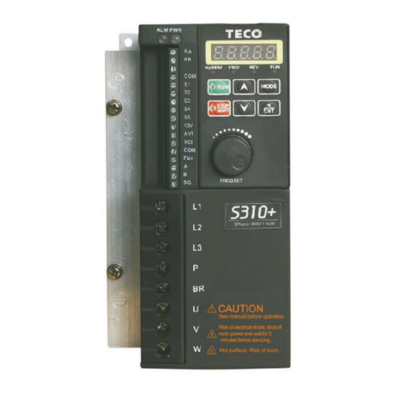
- Page 1 Microprocessor Controlled I G B T Drive Inverter Motor Speed Regulator Operation Manual S310+ Series 400V class 0.75~3.7kW (1.7~6.7kVA)
- Page 2 Distributor: Add: Wuxi High&New Technology Industry Development Zone. Block 65-C ,WuXi, Jiangsu ,China. Postcode:214028 Tel: +86-0510-85227555 Fax: +86-0510-85227556(Electronic) 2018. 4 Website: www.taian-technology.com This manual may be modified when necessary because of improvement of the product, modification, or changes in specification, this manual is subject to change without notice.
-
Page 3: Table Of Contents
3.3.1 Wiring guidelines 3.3.2 Contactor and Circuit Breaker specification and wiring 3.3.3 Precautions for Peripheral Applications Specifications 3.4.1 Product Specifications 3.4.2 General Specifications 3-11 Wiring Diagram S310+ Series Inverter Description of connection terminals 3-12 Outline Dimension 3-13 Chapter 4 Software Index Keypad Description 4.1.1 Keypad Display and Keys... -
Page 4: Chapter 0 Preface
Chapter 0 Preface 0.1 Preface To extend the performance of the product and ensure personnel safety, please read this manual thoroughly before using the inverter. Should there be any problem in using the product that can not be solved with the information provided in the manual, contact your nearest Taian’s technical or sales representative who will be willing to help you. -
Page 5: Chapter 1 Safety Precautions
Chapter 1 Safety Precautions Before Power Up Caution The line voltage applied must comply with the inverter’s specified input voltage.(See product nameplate) Danger Make sure the main circuit connections are correct. L1, L2 and are power-input terminals and must not be mistaken for U, V and W. Otherwise, inverter damage can result. Caution ... -
Page 6: During Power Up
During Power Up Danger When the momentary power loss is short, the inverter still has enough storage power to control the circuit. Therefore, when power is re-applied, the inverter will automatically restart depending on the setup of 04-03. When restarting the inverter, the operation of the inverter is based on the setup of 00-03 and 04-09 and the condition of external switch (FWD/REV button). -
Page 7: During Maintenance
Danger To avoid electric shock, do not take the front cover off when power is on. The motor will restart automatically after stop when auto-restart function is on. In this case, use caution while working near the drive, motor, or driven equipment. ... -
Page 8: Chapter 2 Definition Of Model
Nameplate Data → Inverter model → Input voltage → Output specifications Inverter Models S310+- 4 01- H 3 B C D S310+ Series Supply voltage: Blank:None Specification: B:Built-in 4: 400V D :Built-in H: Standard Type braking unit Keypad Panel Horsepower:... -
Page 9: Chapter 3 Ambient Environment And Installation
Chapter 3 Ambient Environment and Installation 3.1 Environment The environment will directly affect the proper operation and the life span of the inverter, so install the inverter in an environment complying with the following conditions: Ambient temperature: -10℃ ~ +50℃(Power distribution panel: -10℃ ~ +40℃) ... -
Page 10: Environmental Precautions
3.2 Environmental precautions Do not use the inverter in an environment with the following conditions:... -
Page 11: Electrical Installation
3.3 Electrical Installation 3.3.1 Wiring guidelines A. Tightening torque: Required Screwdriver Torques are as listed below: Tightening torque Horsepower Power source Nominal torque for TM1 terminal 0.59/0.08 13/15 380-480V (lbs-ft/kg-m) (lbs-ft/kg-m) 1.5/0.21 13/15 380-480V (lbs-ft/kg-m) (lbs-ft/kg-m) Power Cables Power cables are connected to TM1 terminal block, terminals L1, L2, U, V, W, P1, BR. Choose power cables according to the following criteria: (1) Use copper wires only. -
Page 12: Contactor And Circuit Breaker Specification And Wiring
3.3.2 Contactor and Circuit Breaker specification and wiring. Molded-case circuit breaker/magnetic contactor Teco bears no responsibility to service for failures caused by the following conditions: (1) A molded-case circuit breaker is not installed, or an improper or overrated breaker is used, between the power source and the inverter. -
Page 13: Precautions For Peripheral Applications
3.3.3 Precautions for peripheral applications: Power supply: Make sure the correct voltage is applied to avoid damaging the inverter. A molded-case circuit breaker or fused disconnect must be installed between the AC source and the inverter Molded-case circuit breaker: ... - Page 14 Make external connections according to the following instruction. Check connections after wiring to make sure all connections are correct. (Do not use the control circuit buzzer to check connections) (A) Main circuit’s wiring must be separated from other high voltage or high current power line to avoid noise interference.
- Page 15 When the connection between the inverter and the motor is too long,consider the voltage drop of the cables. Phase-to-phase voltage drop (V) = 3 ×resistance of wire (Ω/km)×length of line (m)×current×10 Carrier frequency must be adjusted based on the motor cable length. Cable length between the inverter and the motor Below 150 ft Below 300 ft...
-
Page 16: Specifications
3.4 Specifications 3.4.1 Product Speci fications Three phase, 380~480V model 4 0 5 S3 1 0 +-□□□-X XX 4 0 1 4 0 2 4 0 3 Horsepower(HP) Max Applicable Motor Output 0. 75 1. 5 2. 2 3. 7 (KW) Rated Output Current(A) 2. -
Page 17: General Specifications
3.4.2 General Specifications S310+ series Item Control Mode V/F or SLV Range 0.01~400.00 Hz 140% /1Hz (SLV mode) Starting torque 1:50 (SLV mode) Speed control range ±1% (SLV mode) Speed control accuracy Setting resolution Digital: 0.01Hz, Analog: 0.06Hz/ 60Hz(10bits) Keypad setting Set directly with▲▼... - Page 18 FUSE protection The motor stops after FUSE melt 400V class: DC Voltage>820V Over Voltage 400V class: DC Voltage>380V Under Voltage Momentary Power Restart can be initiated with spin start . Loss Restart Stall protection can be set in acceleration ,deceleration ,constant Stall protection speed.
-
Page 19: Wiring Diagram S310+ Series Inverter
3.5 Wiring diagram S310+ series inverter Inverter Model: S310+ -203-H1/401-H3/402-H3/403-H3/405-H3 Note 1: Please refer to description of main circuit terminals (P1, BR) and specification of braking resistor for value selection. 2: please avoid connecting output of inverter to the earth. -
Page 20: Description Of Connection Terminals
3.6 Description of connection terminals Descriptions of main circuit terminals Symbol Description Main power input. Model 401/402/403/405:L1/L2/L3 Braking resistor connection terminal: Used in applications when it is required to stop a high inertia load 400V class:1~5HP. rapidly. (refer to specifications of the braking resistor) Inverter outputs Descriptions of control circuit terminals... -
Page 21: Outline Dimension
3.7 Outline Dimension (unit: mm) 1)Frame1 : Three phase : S310+-401-H3(With No Fan) Three phase : S310+--402-H3(With Fan) unit: mm No dimensioning tolerance:±0.4mm Models:S310+-401-H3 Models:S310+-402-H3 3-13... - Page 22 2)Frame2 : Three phase : S310+-403-H3 Three phase : S310+-405-H3 unit: mm No dimensioning tolerance:±0.4mm Models:S310+-403-H3 Models:S310+-405-H3 3-14...
-
Page 23: Chapter 4 Software Index
Chapter 4 Software Index 4.1 Keypad Description 4.1.1 Keypad Display and Keys 401/402/403/405 models: type name Description Monitor inverter signals, view / edit parameters, fault / alarm display. Hz/RPM: Frequency Rotational Speed LED FWD: 5 Digit LED LED ON when inverter is running in forward direction, DISPLAY Display flashing when stopping. - Page 24 4.1.2 Display Description Eight Segment Display Description Actual Display Actual Display Actual Display Actual Display ° Display output frequency Set Frequency Reference LED lights on LED flashes Selected flashes...
-
Page 25: Display Description
LED Digital tube display Display Description 1. Displays the frequency reference at stop operation. 2. Displays the actual output frequency during run operation. Displays parameter code. Displays the setting value of parameter. Displays input voltage. Displays inverter current. Displays DC Bus Voltage. Displays temperature. -
Page 26: Function Of Digital Tube Display
4.1.3 Function of digital tube display Basic display: Special keys: ▲ ▼ The digits can be selected by short press and can only change one unit;the select digits can be changed continuously by long press. -
Page 27: Operational Examples Of Keypad
4.1.4 Operational examples of Keypad Operation Instruction of the LED keypad Power On ● :LED fully Lit LED flashing 2 seconds later or after Enter operation signal, Press DSP to modify the display ‧ Hz/RPM ‧ Hz/RPM ‧ Hz/RPM — —... -
Page 28: Control Mode Selection
(1) Motor rated current (06-01)will add up all the rated current of the motors。 (2) The others set the appropriate V/F curve parameters (05-04~05-09). 3. When the motor nameplate is unknown,the inverter will be setted to the internal value of TECO standard motor parameters. -
Page 29: S310+ Programmable Functions List
4.2 S310+ Programmable Functions List description Parameter group Parameter group Group Basic Parameters Group External terminal digital signal input function group External terminal analog signal input function group Group Preset Frequency function group Group Group Start/Stop command group Group V/F command group Motor parameters group Group Protection function group... - Page 30 Group 00: Basic Parameters Code Parameter Name Setting Range Default Unit Attribute 0:V/F mode 00-00 Control Mode Selection 1: SLV mode 1 ~ 7 00-01 Volts/Hz Patterns (V/F) 0: Forward 00-02 Motor rotation 1: Reverse 0: Keypad Main Run 00-03 1: External Run/Stop Control Command Source Selection 2: Communication...
- Page 31 Group External terminal digital signal input function group Code Parameter Name Setting Range Default Unit Attribute 01-00 0: Forward/Stop Command Multifunction Input Term. S1 01-01 Multifunction Input Term. S2 1: Reverse/Stop Command 01-02 2: Preset Speed unit 0 (3-02) Multifunction Input Term. S3 01-03 3: Preset Speed unit 1 (3-03) Multifunction Input Term.
- Page 32 Group External terminal digital signal input function group Code Parameter Name Setting Range Default Unit Attribute 01-15 0.01~9.99 1.00 Pulse frequency multiple Pulse input filtering 01-16 0~100 coefficient Count value reaches the 01-17 0~9999 setting value Pulse input counting filtering 01-18 1~100 coefficient...
- Page 33 Group Multi-Speed Parameters Code Parameter Name Setting Range Default Unit Attribute 0: Part acceleration and deceleration time are set by acceleration and Acceleration and Deceleration 03-00 deceleration time1 Selection of Multi-Speed 1: Part acceleration and deceleration time are set by independently Frequency Setting of 03-01 0.00 ~ 400.00...
- Page 34 Group Multi-Speed Parameters Code Parameter Name Setting Range Default Unit Attribute Acceleration Time Setting of 03-31 0.1 ~ 3600.0 10.0 Multi Speed 7 Deceleration Time Setting of 03-32 0.1 ~ 3600.0 10.0 Multi Speed 7 03-33~03-48 Reserved Group Start/stop command group Code Parameter Name Setting Range...
- Page 35 Group V/F command group Code Parameter Name Setting Range Default Unit Attribute 05-10 0.10 ~400.00 1.50 Minimum Frequency 05-11 Minimum Frequency Voltage 400V:0.0 ~ 528.0 22.8 05-12 Reserved Low-pass Slip compensation 05-13 0.05 ~10.00 0.10 Filter time 05-14 Reserved Auto-Torque compensation 05-15 *1*5 0.1~1000.0...
- Page 36 Group Protection Parameters Code Parameter Name Setting Range Default Unit Attribute Stall Prevention Level In Run 07-03 50 ~ 200 Mode (%) over voltage Prevention Level in 80~100 (OV %) 07-04 Run Mode (%) 0: Enable motor Protect by relay 07-05 Electronic Motor Overload Protection Operation Mode OL1...
- Page 37 Group PID Parameters Code Parameter Name Setting Range Default Unit Attribute 4 : Feedback D Control 09-00 PID mode selection (Fwd/Rev, Reversed Characteristics) 09-01 Feedback Gain coefficient 0.00 10.00 1.00 09-02 Proportional Gain 10.0 09-03 Integral Time 100.0 10.0 09-04 Differential Time 0.00 10.00 0.00...
- Page 38 Group Keypad display group Code Parameter Name Setting Range Default Unit Attribute xxxx0: Disable Motor Current Display xxxx1: Enable Motor Current Display xxx0x: Disable Motor Voltage Display xxx1x: Enable Motor Voltage Display 11-00 Display Mode 00000 xx0xx: Disable Bus Voltage Display xx1xx: Enable Bus Voltage Display x0xxx: Disable temperature Display x1xxx: Enable temperature Display...
- Page 39 Group Auto Run function group Code Parameter Name Setting Range Default Unit Attribute 0: Disabled. 1: Single cycle.(Continues to run from the Unfinished step if restarted). 2: Periodic cycle. (Continues to run from the unfinished step if restarted). 3: Single cycle, then holds the speed Of final Auto Run( sequencer) mode 13-00 step to run.
-
Page 40: Parameter Function Description
4.3 Parameter Function Description Group0- The basic parameters group 00-00 Control Mode 【0】: V/F mode range 【1】: Vector mode To select the appropri ate vecto r control mode o r V/F mode ac cording to the load characteristi cs. 1) If V/F mode is selected, please set parameters, group5 to comply with the load features. 2)... - Page 41 ※Note: When 00-08 = 0 Hz and frequency command is 0 Hz; the inverter will stop at 0 speed. When 00-08 > 0 Hz and frequency command ≦00-08, the inverter will output the 00-08 preset value. 00-09 Acceleration time 1 【0.1~3600.0】...
- Page 42 ※Note: 1.As 3 wire control mode is selected, the terminal S1, S2 and S3 is not controlled by 01-00, 01-01 and 01-02. 2. 10-01=1, the reverse command is unavailable. 00-12 Jog Frequency 【1.00~25.00】Hz range 00-13 Jog Acceleration Time 【0.1~25.5】Sec range 00-14 Jog Deceleration Time 【0.1~25.5】Sec...
- Page 43 External terminal digital signal input function group Group1- 01- 00 Multifunction input terminals controlling S1 01- 01 Multifunction input terminals controlling S2 01- 02 Multifunction input terminals controlling S3 01- 03 Multifunction input terminals controlling S4 01- 04 Multifunction input terminals controlling S5 【0】:...
- Page 44 and then ON again, or press the run key in keypad mode, the inverter will restart again up and ramps up to the command frequency. If the emergency signal is released before the inverter stops completely, the inverter still carries out the emergency stop.
- Page 45 01- 08 Up/Down keep Frequency mode ,and he inverter stops: When Up/Down is used, 【0】:The set frequency will be maintained. range 【1】:the preset frequency is reset to 0 Hz 【2】:The set frequency will be maintained.,and the UP/Down is available. 1). 01-08=0: the inverter will accelerate to the speed set in parameter 03- 01 as receiving the Run command and run at such certain speed.
- Page 46 A.01-09/10= 3: Arbitrary frequency consistency Fout = 01-11 01-12 B.01-09/10= 4: Frequency detection Fout > 01-11 C.01-09/10= 5: Frequency detection Fout < 01-11 4-24...
- Page 47 01- 13 s1~s5 switch type select xxxx0: s1 xxxx1:s1 xxx0x: s2 xxx1x:s2 range xx0xx: s3 xx1xx:s3 x0xxx: s4 x1xxx:s4 0xxxx: s5 1xxxx:s5 ※Note: “NO”: Normal open, “NC”: Normal close. The switches type is decided by 01-13/01-14, Because of different types of switches, select switches type is necessary. If set 01-13=0 0 0 0 0, means S1~S5 types of switches is Normal open, otherwise, if each bit of 01-13 is set to “1”, types of switches is Normal close.
- Page 48 from ON to OFF is fixed to 100ms. Group 02- Exte rnal te rmi nal a nalog signal inp ut function gro up 02- 00 AVI(AIN) and ACI analog Input signal type select (AIN) 【0】:0~10V(0~20mA) 0~20mA 【1】:0~10V(0~20mA) 4~20mA range 【2】:2~10V(4~20mA) 0~20mA 【3】:2~10V(4~20mA)...
- Page 49 02- 07 ACI signal verification Scan Time 【1~200】2msec range 02- 08 ACI Gain 【0 ~ 200】% range 02- 09 ACI Bias 【0.0 ~ 100.0】% range 02- 10 ACI Bias Selection 【0】: positive 【1】: Negative range 02-11 ACI Slope 【0】: positive 【1】:...
- Page 50 2. Example: The setting of figure 4-18A: The setting of figure 4-18B: 2-02 2-03 2-04 2-05 2-02 2-03 2-04 2-05 2-09 2-09 /2-08 /2-09 /2-10 /2-11 /2-08 /2-09 /2-10 /2-11 100% 100% 100% 100% 100% 100% 100% 100% Bias Bias 100% 60Hz 60Hz...
- Page 51 Group3- preset Frequency function group 03- 00 Acceleration and Deceleration Selection of Multi-Speed 【0】:Part acceleration and deceleration time are set by acceleration and Range deceleration time1 【1】:Part acceleration and deceleration time are set by independently 03- 01~03-08 Frequency Setting of Speed-Stage Preset Speed 0 ~...
- Page 52 Frequency Hz Forward …… Time Panel freq Preset speed 1 Preset speed 2 mode2:When the run command is continuous , calculate acceleration and deceleration time of each segment like this (03 17) (03 01) (03 20) [(03 01) (03 02)] ...
- Page 53 Group4- Start/Stop command group 04-01 Stopping Method Selection 【0】: Enhanced braking capacity Range 【1】: Coast to stop 1)04-01=0: the inverter will decelerate to 0Hz in preset deceleration time after receiving the stop command. 2)04-01=1: the inverter will stop output as receiving the stop command. The motor will inertia Coast to stop. 04-03 Momentary power loss and restart 【0】:...
- Page 54 04-17 / 04-15is the action time and start frequency of DC braking, as graph below: 04-18 Over excitation Deceleration Gain 【0】: DC Injection Brake @running enable Range 【1】: DC Injection Brake @ running disable 04-18=0, DC Injection Brake @running enable; 04-18=1, If the running signal is always in, the frequency is reduced to STP0, and there is a dc brake at run time.
- Page 55 Group5- V/F command group 05- 01 No-load Current of Motor (Amps AC) Range 05- 02 Motor rated Slip Compensation 【0.0 ~ 100.0】% Range 05- 03 V/f max voltage 【400V:323.0 ~528.0】Vac Range 05- 04 Maximum Frequency 【0.20 ~ 400.00】Hz Range 05- 05 Maximum Frequency Voltage 【400V:323.0 ~528.0】Vac Range...
- Page 56 2) 00-01 = 1-6 V / F Pattern (Refer to following list ): type Function 00-01 type Function 00-01 V/F pattern V/F pattern V (%) V (%) General General Use 1.5 3.0 60 400 1.5 2.5 50 400 V (%) V (%) High start High start...
- Page 57 voltage ratio Fixed VF curve B,C corresponding output voltage is shown below:(Uints:V) 00-01 Voltage ratio% Output voltage 30.4 22.8 10.5 57.0 39.9 95.0 29.3 Custom VF curve 00-01 = 7, the default output voltage is shown below: 400V frequency 0.50 10.00 25.00 50.00...
- Page 58 Group6- Motor parameter group 06- 00 Motor Rated Voltage (VAC) Range 06- 01 Motor Rated Current (Amp AC) Range 06- 02 Motor Rated Power (kW) Range 06- 03 Motor Rated Speed (RPM) Range 06- 04 Motor Rated Frequency (Hz) Range 06- 05 Motor Parameter Auto Tuning 【0】: Invalid...
- Page 59 Group7- Protection function group 07- 00 Stall Prevention Function 【xxxx0】: Stall prevention is enabled in acceleration 【xxxx1】: Stall prevention is disabled in acceleration. 【xxx0x】: Stall prevention is enabled in deceleration. 【xxx1x】: Stall prevention is enabled in deceleration. 【xx0xx】: Stall prevention is enabled in operation. Range 【xx1xx】:...
- Page 60 07- 13 OH over heat Protection ( cooling fan control) 【0】:Auto (Depends on temp.) 【1】:Operate while in RUN mode Range 【2】:Always Run 【3】:Disabled 1) 07-13=0:The fan runs as the inverter senses temperature rises. Thusly, extend the service period. 2 )07-13=1:The fan runs while the inverter is running. 3) 07-13=2:The fan is continuously running regardless of the action of the inverter.
- Page 61 08- 06 Communication time-out detection time 【0.0~25.5】Sec Range 08- 07 Communication time-out operation selection 【0 】:Deceleration to stop and display dot. 【1】:Coast to stop and display dot. Range 【2】:Continue operating and display dot. 1)Time-out detection time: 00.0~25.5sec; setting 00.0 sec: disable time-out function. *Cannot be modified during communication 08- 08 Err6 fault tolerance times...
- Page 62 09- 07 PID Output Lag Filter Time 【0.0~2.5】Sec Range 09-07:Update time for output frequency. ※Note:PID is used for the control of output flow of the converter, the control of external fan air volume and temperature control, and the control flow is as follows: 1) When performing PID control, please set the terminal ACI on TM2 as the PID feedback signal, i.e.
- Page 63 09- 14 Sleep Frequency Level 【0.00~400.00】Hz Range 09- 15 Sleep Function Delay Time 【0.0~25.5】Hz Range 09- 16 Wake up frequency Level 【0.00~400.00】Hz Range 09- 17 Wake up function Delay Time 【0.0~25.5】Hz Range PID SLEEP MODE: 09-00=1(PID Enable) 02-06=0(PID FEEDBACK Enable) 00-05=PID setting frequency source (Target Value) 09-14: set the sleep threshold frequency, Unit: HZ 09-15: set the time for sleep delay, Unit: sec...
- Page 64 Group10- Assistant function group 10- 01 Reverse operation control 【0】:Reverse command is enabled Range 【1】:Reverse command is disabled 10-01=1, the reverse command is disabled. 10- 03 Carrier Frequency 【1~12】kHz Range Carrier Carrier Carrier 10-03 10-03 10-03 Frequency Frequency Frequency 1kHz 5kHz 9kHz 2kHz...
- Page 65 Note: a. Regardless of the stall prevention period, actual acceleration and deceleration time =preset acceleration / deceleration time + S curve time. b. Please set the S curve time separately in the parameter (10-07~10-10) c. When S curve time (10-07~10-10) is set as 0, the S curve function is disabled. d.
- Page 66 Group11-keypad display group 11- 00 Display Mode xxxx0:Disable Motor Current Display xxxx1:Enable Motor Current Display xxx0x:Disable Motor Voltage Display Range xxx1x:Enable Motor Voltage Display xx0xx:Disable Bus Voltage Display xx1xx:Enable Bus Voltage Display x0xxx:Disable temperature Display x1xxx:Enable temperature Display 11- 01 Custom Units (Line Speed) Value 【0~65535】Rpm Range...
- Page 67 3) When pressing ‘Reset’ at 12-02, the three fault log will be cleared when the reset key is pressed. The log content will change to 1. ---, 2. ---, 3. ---. 4) E.g. the fault log content is ‘1.OC-C’; this indicates the latest fault is OC-C, etc. 12- 03 Accumulated Operation Time 1 (Hours) 【0~23】Hours...
- Page 68 Note: when the multi-function terminal is set to 9, and terminal conduct, this function enables. 1) Auto Run( sequencer) mode selection (13-00) 2) Auto Run( sequencer) mode setting (13-01~13-39) ●Auto run mode (sequencer) operation as selected by parameter 13-00 can be set up as follows: a.
- Page 69 13-00 = 3(or 6) Panel Frequency (3-01)=15 Hz 13-01=30Hz 13-02=50Hz 13-15=20Hz 13-16=20s 13-17=25s 13-18=30s 13-23=40s 13-32=1 13-33=1 13-34 = 1 13-39=1(FWD) 13-03~13-06=0Hz ,13-19~13-22=0s ,13-35~13-39 = 0 Note:13-00 = 1~3 : If the inverter stops and re-starts, it will continue running from the unfinished step, according to the setting of 13-00.
-
Page 70: Chapter 5 Troubleshooting And Maintenance
Chapter 5 Troubleshooting and Maintenance Error Display and Corrective Action 5.1.1 Error Display and Corrective Action Faults which can not be recovered manually Display Fault Cause Corrective Action -OV- Voltage too high Detection circuit Return the inverter when stopped malfunction -LV- 1. -
Page 71: Operation Errors
deceleration time is too short. time OC-S 1.Short circuit between the 1.Inspect the motor motor coil and the case 2. Inspect the wiring 2.Short circuit between Over current at 3. Replace the transistor start motor coil and ground module 3. the IGBT module damaged OV-C 1.Set a longer... -
Page 72: Special Conditions
setting error is beyond the actual according to the specified allowable range. range Err5 1. Control command sent 1. Issue enable command Modification of during communication. before communication parameter is not 2. Attempt to modify the 2. Set parameters available in function 08-02 ~ 08-05 08-02 ~ 08-05 function communication... -
Page 73: General Troubleshooting
OH-C, OV-C, OC-S, OC-d, OC-C, OC-a, OL2, OL1, the Alarm LED flashes slowly. In order to release from the alarm, you can cut off the power of inverter, then turn it on again. 5.2 General troubleshooting Status Checking point Remedy Are wiring for output terminals Wiring must match U, V, and W terminals of Motor runs... -
Page 74: Quick Troubleshooting Of S310+ Series
5.3 Quick troubleshooting of S310+ series... - Page 76 Troubleshooting for OC, OL error displays...
- Page 77 Troubleshooting for OV, LV error...
- Page 78 The motor can not run...
- Page 79 Motor Overheating Motor runs unevenly 5-10...
-
Page 80: Routine And Periodic Inspection
5.4 Routine and periodic inspection To ensure stable and safe operations, check and maintain the inverter at regular intervals. The table below lists the items to be checked to ensure stable and safe operations. Check these items 5 minutes after the “Charge” indicator goes out to prevent injury to personnel by residual electric power. -
Page 81: Maintenance And Inspection
5.5 Maintenance and Inspection To ensure long-term reliability, follow the instructions below to perform regular inspection. Turn the power off and wait for the charge indicator (LED) to go out before inspection to avoid potential shock hazard from the charge stored in high-capacity capacitors. 1、... -
Page 82: Ac Reactor And Dc Reactor Specification At Input Side
Chapter 6 Peripherals Components 6.1 AC reactor and DC reactor specification at input side Braking Braking AC inductance Braking resistor resistor torque Model at input side Specification Duty Current Inductance Number Cycle (%) (Ω) (mH) used S310+-401-H3XXX S310+-402-H3XXX S310+-403-H3XXX S310+-405-H3XXX 10.0 6.2 Digital operator and extension cable S310+-401/402/403/405-H3:... - Page 83 Hz/RPM MODE STOP RESET FREQ.SET 2. Dimension for remote keypad a. Keypad hatch Installation Dimension Fixation board 安装固定板 厚度≤4.5mm Deep≤45mm...
- Page 84 Appendix 1: S310+parameter setting list Customer Inverter Model Site Location Contact Phone Address Parameter Setting Parameter Setting Parameter Setting Parameter Setting code content code content code content code content 00-00 05-05 10-03 02-12 00-01 02-13 05-06 10-04 00-02 02-14 05-07 10-07 00-03 03-00...
-
Page 85: Appendix
Appendix 2: S310+ MODBUS Communication protocol 1. Communication Data Frame S310++ series inverter can be Communication controlled by the PC or other controller with the Communication protocol, Modbus ASCII Mode & Mode RTU, RS485 or RS232. Frame length maximum 80 bytes. 1.1Hardware installation Slave S310+ Slave S310+... - Page 86 1.2.2 FOR RTU MODE MASTER(PLC etc.)send request to SLAVE, whereas SLAVE response to MASTER.The signal receiving is illustrated here. The data length is varied with the command(Function). SLAVE Address Function Code DATA CRC CHECK Signal Interval **The interval should be maintained at 10ms between command signal and request. 1.3 SLAVE Address 00H : Broadcast to all the drivers 01H : to the No.01 Drivers...
- Page 87 (2)Exclusive OR the first 8-bit byte of the message with the low-order byte of the 16-bit CRC register, putting the result in the CRC register. (3)Shift the CRC register one bit to the right (toward the LSB), Zero-filling the MSB, Extract and examines the LSB.
- Page 88 Error Description Code Function Code Error Address Error Data Amount Error DATA Over Range Writing Mode Error 4. Inverter Control 4.1Command Data (Readable and Writable) Content Register No. Reserved 2500/A000H Operation Signal Description Operation Command Stop Reverse Command Reverse Forward Reserved Fault Reset Reset...
- Page 89 4.2Monitor Data(Only for reading) Register No. Content Description Operation state Stop Direction state Reverse Forward Inverter operation prepare ready unready state Abnormal Abnormal 2520/A020H DATA setting error Error Reserved Reserved Reserved Reserved abnormity Code Description Code Description 00 Reserved 01 OH(Inverter over heat) 02 OC(Over current at stop) 03 LV(Under voltage) 04 OV(Over voltage)
- Page 90 Content Register No. Description Terminal S1 Terminal S2 Terminal S3 Terminal S4 Terminal S5 Sequence reserved input status Multi-function Output1 (RELAY1) reserved 2522/A022H reserved reserved reserved reserved reserved Contact output reserved reserved reserved frequency command (100/1Hz) 2523/A023H Output frequency (100/1Hz) 2524/A024H Output voltage command (10/1V) 2525/A025H...
- Page 91 3、Read data Quantity≥1. (Example) Read the SLAVE station No:01 ,S310+ drive’s frequency command. ASCII Mode Instruction Message Response Message (Normal) Response(Fault) SLAVE SLAVE SLAVE Address Address Address Function Function Function Code Code Code DATA number Error Code Start Address LRC CHECK First holding register...
- Page 92 ASCII Mode Instruction Message Response Message (Normal) Response(Fault) SLAVE SLAVE SLAVE Address Address Address Function Function Function Code Code Code Error Code Test Code Test Code LRC CHEC DATA DATA LRC CHECK LRC CHECK RTU Mode Instruction Message Response Message (Normal) Response(Fault) SLAVE SLAVE...
- Page 93 ASCII Mode Instruction Message Response Message (Normal) Response(Fault) SLAVE SLAVE SLAVE Address Address Address Function Function Function Code Code Code Error Code Start Start Address Address LRC CHECK DATA DATA LRC CHECK LRC CHECK RTU Mode Instruction Message Response Message (Normal) Response(Fault) SLAVE SLAVE...
- Page 94 3、Read data Quantity≥1. (Example)Set SLAVE station No:01, S310+ drive as forward run at frequency reference 60.0HZ. ASCII Mode Instruction Message Response Message (Normal) Response(Fault) SLAVE SLAVE SLAVE Address Address Address Function Function Function Code Code Code Error Code Start Start Address Address LRC CHECK...
- Page 95 Next High DATA High CRC-16 * DATA Numbers are the actual number timers 2 6.Comparison list between parameter and register Note: Parameter register No.: GGnnH,“GG”means Group number ,“nn” means Parameter number for example: the address of Pr 08-03 is 0803H. the address of Pr 10-11 is 0A0BH Register Function Register...
- Page 96 0302H 03-02 0402H 0502H 05-02 Reserved 0303H 03-03 0403H 04-03 0503H 05-03 0304H 03-04 0404H 0504H 05-04 Reserved 0305H 03-05 0405H 0505H 05-05 Reserved 0306H 03-06 0406H 0506H 05-06 Reserved 0307H 03-07 0407H 0507H 05-07 Reserved 0308H 03-08 0408H 04-08 0508H 05-08 0309H...
- Page 97 0704H 07-04 0804H 08-04 0705H 07-05 0805H 08-05 0706H 07-06 0806H 08-06 … … 0807H 08-07 070CH 0808H 08-08 Reserved 070DH 07-13 Register Function Register Function Register Function ) Group09( Reserved Group10 Group11 0A00H 0B00H 11-00 Reserved 0A01H 10-01 0B01H 11-01 0A02H 0B02H...
- Page 98 0D10H 13-16 0D11H 13-17 0D12H 13-18 0D13H 13-19 0D14H 13-20 0D15H 13-21 0D16H 13-22 0D17H 13-23 0D18H Reserved 0D19H Reserved 0D1AH Reserved 0D1BH Reserved 0D1CH Reserved 0D1DH Reserved 0D1EH Reserved 0D1FH Reserved 0D20H 13-32 0D21H 13-33 0D22H 13-34 0D23H 13-35 0D24H 13-36 0D25H...
- Page 99 Appendix 3 :S317+ Parameters Description 1、 Add parameters and modify Defult values as follows: Description Range Defult NOTE Code Electronic Motor Overload 0: Enable motor Protect by relay 07-05 Protection Operation Mode OL1 1: Disable motor Protect by relay 0: Auto (Depends on temp.) OH over heat Protection 1: Operate while in RUN mode 07-13...
Need help?
Do you have a question about the S310+ Series and is the answer not in the manual?
Questions and answers