TECO E510 Quick Start Manual
Hide thumbs
Also See for E510:
- Instruction manual (223 pages) ,
- Quick start manual (9 pages) ,
- Instruction manual (116 pages)
Table of Contents
Advertisement
Quick Links
Quick Start Guide
This guide is to assist you in installing and running the inverter and verify that it is
functioning correctly for it's main and basic features.
For detailed information and if there are any doubts please refer to the instruction manual.
Step 1
Supply & Motor connection
1) Ensure that the Inverter & the motor have the correct
KW power and voltage ratings.
Motor full load amps must not exceed the Inverter rating.
2) Ensure that the supply & Motor cables are connected
Correctly prior to power up.
3) For single phase supply, use L1& L3 ( N) on units which
have 3 supply terminals.
On units with two supply terminals L1&L2, connect live to L1
and Neutral to L2.
4) Connect motor cable to terminals T1,T2 &T3.
(Swap two leads If motor runs in reveres direction).
5) Connect supply Earth and the motor Earth to the drive Earth
terminal.
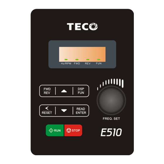
TECO E510 Inverter
Page 1 of 8
Note:-
I ) For detailed installation
and wiring refer to the
manual.
Instruction
12/06/13
Advertisement
Table of Contents

Related Manuals for TECO E510


Summary of Contents for TECO E510
-
Page 1: Quick Start Guide
TECO E510 Inverter Quick Start Guide This guide is to assist you in installing and running the inverter and verify that it is functioning correctly for it’s main and basic features. For detailed information and if there are any doubts please refer to the instruction manual. - Page 2 Apply power to the drive Step 2 Apply power to the drive, the display will briefly show the supply voltage 220V followed by flashing. 05.0 This is the default ( factory set) frequency. If the unit has been used previously then it will show the last frequency programmed.
- Page 3 Remote speed reference and Remote run Remote mode wiring. Speed reference and Run signals. Step 1 1) Ensure that you have carried out installation & wiring requirements as per step1 quick start guide on previous page before you proceed. 2) For analogue signal type. 2-10V or 0-10V dc. Use the terminal AVI.
- Page 4 Step 4 using remote speed reference.(Potentiometer,0-10vdc or 4- 20ma ) 1) To run. Activate the remote run switch connected to terminals S1 ( FWD) or S2 ( REV) as required,. Parameter 00-02=00-01 The frequency will ram up to the frequency set by one of the following:- How to alter parameters ...
- Page 5 Basic Quick Start Parameter List Parameter Default Range Note 00-00 0: V/F control mode 1: Vector mode (SLV) 0.1~3600.0 00-14 10.0 Acceleration time in Secs 0.1~3600.0 00-15 10.0 Deceleration time in Secs 0: Forward/Stop-Reverse/Stop 00-04 1: Run/Stop-Reverse/Forward 2: 3-Wire Control Mode-Run/Stop 0.01~650.00 00-12 50/60Hz...
- Page 6 Control Modes & Auto Tune E510 provides two control modes Select the relevant control mode for the application, using parameter 00-00 Control mode. Default control mode is V/f. V/f can be used for most applications specifically multi-motor or applications where auto tune is not successful or when a customized v/f pattern may be required.
- Page 7 *1: Independent protection circuit is suggested to be installed for the purpose of protecting the circuit. *2: The jumper wire between SF and SG is removed, the inverter stops output. *3: JP1:NPN/PNP select, JP2:AI1 0~10V/0~20mA select, JP3:AI2 0~10V/0~20mA select Model: 200V: E510-2P5-H1F/ E510-201-H1F/ E510-202-H1F/ E510-203-H1F. Page 7 of 8 12/06/13...
- Page 8 Single /Three Phase: 200V: E510-2P5-H/ E510-201-H/ E510-202-H/ Model: E510-203-H Page 8 of 8 12/06/13...
Need help?
Do you have a question about the E510 and is the answer not in the manual?
Questions and answers