
Related Manuals for probst SH-1000-MINI


Summary of Contents for probst SH-1000-MINI
- Page 1 Operating Instructions Translation of original operating instructions Vacuum-Lifting-Device SH-1000-MINI SH-1000-MINI-E 5240.0020...
- Page 2 Bitte beachten Sie, dass das Produkt ohne vorliegende Betriebsanleitung in Landessprache nicht eingesetzt / in Betrieb gesetzt werden darf. Sollten Sie mit der Lieferung des Produkts keine Betriebsanleitung in Ihrer Landessprache erhalten haben, kontaktieren Sie uns bitte. In Länder der EU / EFTA senden wir Ihnen diese kostenlos nach.
-
Page 3: Table Of Contents
Operating Instructions EC-Declaration of Conformity Contents EC-Declaration of Conformity ..........................4 General ..................................5 Authorized use ................................5 Survey and construction ............................7 Technical data ................................7 Safety ..................................8 Safety Symbols ................................8 Safety Marking ................................8 Function Control ................................11 3.3.1 Safety at work ...............................11 Instructions for the Company .......................... - Page 4 Suction pads/ seals ..............................32 Vacuum filter ................................32 Warning device (audible) ............................32 Leak test ................................... 33 Safety procedures ..............................33 7.10 Hints to the type plate ............................. 34 7.11 Hints to the renting/leasing of PROBST devices ....................34 3 / 34...
-
Page 5: Ec-Declaration Of Conformity
DIN EN 60204-1 (IEC 60204-1) Safety of machinery, electrical equipment of industrial machines. Part 1: General requirements. Authorized person for EC-documentation: Name: J. Holderied Address: Probst GmbH; Gottlieb-Daimler-Straße 6; 71729 Erdmannhausen, Germany Signature, information to the subscriber: Erdmannhausen, 20.03.2019................(M. Probst, Managing director) -
Page 6: General
The load is additionally secured with the standard load securing chain. • Various suction plates can be fitted to the device (SH-1000-MINI) via a quick release locating pin, enabling it to be used for many different purposes and with many different loads. - Page 7 Standard suction plates are not suitable for the transport of glass plates! Only suction plates of the manufacturer PROBST shall be used, which shows doubtless a maximum load capacity at a pressure of - 0.6 bar at the carrying capacity sticker. In unclear circumstances the vacuum device and the suction plate may not be put into operation.
-
Page 8: Survey And Construction
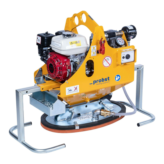
Operating Instructions General Survey and construction Lifting eye for crane hook of Lifting eye for crane hook of the carrier(curbs) the carrier (stone slabs etc. Handle Manometer rotatable by 180° then usable as support legs Load securing chain Warning device Load securing Vacuum pump chain... -
Page 9: Safety
Operating Instructions Safety Safety Safety Symbols Danger to life! Identifies imminent hazard. If you do not avoid the hazard, death or severe injury will result. Hazardous situation! Identifies a potentially hazardous situation. If you do not avoid the situation, injury or damage to property can result. - Page 10 Operating Instructions Safety The device must never be placed on the suction plate when not in 29040446 139x39 use, otherwise the suction plate will be damaged! Instead, turn the side handles 180° and use them as a stand. Do not lift any components off-centre (always in center ogf gravity). 2904.0383 It is not allowed to position suction plates off-centre, 29040337 65x200 mm...
- Page 11 Operating Instructions Safety WARNING SIGN Symbol Meaning Order-No.: Size: Danger of squeezing the hands. 2904.0221 30 mm 2904.0220 50 mm 2904.0107 80 mm Warning of electric voltage. 2904.0397 31x37 mm REGULATORY SIGN Symbol Meaning Order-No.: Size: 2904.0665 30 mm Each operator must have rea and understood the operating 2904.0666 50 mm...
-
Page 12: Function Control
Operating Instructions Safety Function Control • Before using the device check the functions and the working condition. • Maintenance and lubrication are only permitted when device is shut down! • Do not use the device, until all faults which can cause safety hazards are removed. •... -
Page 13: Instructions For The Company
Operating Instructions Safety Instructions for the Company The lifting devices are manufactured according to current technical standards and are safe. However, they will present hazards • if they are not operated by qualified or, at the least, trained staff, • if they are used contrary to the approved applications. -
Page 14: Special Hazards
Operating Instructions Safety Special Hazards • The operating range has to be covered for unauthorized persons, especially children. • The workplace has to be sufficiently illuminated. • Take care when handling wet, dirty and not solidified components. • The working with the vacuum lifting device in case of atmospheric editions under 3° C ( 37,5° F) is forbidden! Because the goods could be fall down caused by dampness or freezing. -
Page 15: 3.10 Inspecting The Vacuum Hoses And Hose Clamps
Operating Instructions Safety 3.10 Inspecting the vacuum hoses and hose clamps • Check that all vacuum hoses and hose clamps are securely seated. Tighten any loose connections. 3.10.1 Testing the vacuum reservoir • See the sub-section "Leak test" in the section ”Maintenance” •... -
Page 16: Behaviour In Emergencies
Operating Instructions Safety 3.13 Behaviour in Emergencies An emergency situation exists when • power suddenly fails (device switches off), • the vacuum pressure drops below -0.6 bar to the red section on the scale of the vacuum gauge. Lower the load immediately if possible. If this is not possible, immediately leave the dangerous area near the load, since it will be dropped from the device. -
Page 17: Installation
Operating Instructions Installation Installation Mechanical connection Use only original accessories, in case of doubt consult the manufacturer. Take care that the carrying capacity / working load limit (WLL) of the lifting device/carrier is not exceeded, through the load of the device, the attaching devices (turning device, fork sleeves etc.) and the additional load of the gripping goods! Gripping devices always have to be gimballed, so they can swing freely in any position. -
Page 18: Fork Sleeves (Optional)
Operating Instructions Installation 4.1.3 Fork sleeves (optional) To establish a mechanical connection between the fork lift truck and the fork sleeves you have to put the forks into the fork sleeves and fix it with the locking bolt or with a chain/rope, connected to the eyelet on the fork sleeves and the lift frame. -
Page 19: Positioning Of Suction Plates
Operating Instructions Installation Positioning of suction plates For each application of the device (SH 1000 mini b) the different suction plates must be fastened to the corresponding place to the device. The device (SH 1000-MINI) with sucked in load (stone slab) must always hang on the carrier (e.g. excavator) vertical. -
Page 20: Electrical Installation
Operating Instructions Installation Electrical Installation • The electrical installation and connection of the device to the power supply may only be carried out by qualified personnel. Initiation The device must be installed and maintained by qualified personnel, mechanics and electricians. Mounting the suction pad to the lifting device Support Lifting device... -
Page 21: Refueling The Engine
Operating Instructions Installation Refueling the engine • Gasoline is highly flammable. Always keep the fuel tank closed. • Do not smoke or allow flames when using gasoline. Do not inhale the fumes. • To refuel the engine, switch off the device and engine. •... - Page 22 Operating Instructions Installation Vacuum- device Spreader Fig. 3 Suction plate 21 / 34...
-
Page 23: Attaching The Safety Chain (Of The Optional Spreader Bar)
Operating Instructions Installation 4.7.1 Attaching the safety chain (of the optional spreader bar) • Lift the device with the sucked load just a little (approx. 20 cm) • Then remove both safety chains from the chain cases of the spreader bar (TRA). •... -
Page 24: Operating
Operating Instructions Operating Operating Safety Instructions • Wear safety shoes and gloves. • Never exceed the maximum lifting capacity of the device or of the crane or hoist used. Include the weight of the lifting device. Observe the name plate. •... -
Page 25: Lifting Load
Operating Instructions Operating 5.2.1 Lifting load: • Start the gasoline engine (further details → see HONDA operating instructions). and switch on the warning device • Position the lifting device directly above the load. Do not pull to the side. Distribute load evenly. •... -
Page 26: Releasing The Load
Operating Instructions Operating 5.2.2 Releasing the load: • Lower the load to a safe and clear, level surface, to ensure that the load cannot slip or tip over. • Shift the bushing on the slide valve (A) back. The load is released. - Page 27 Operating Instructions Operating • Open the condensate drain screw on the bottom of the storage container. Drain the water completely and tighten the drain screw securely again. condensate drain screw 26 / 34...
-
Page 28: Downtime
Operating Instructions Operating 5.2.4 Downtime Store the device in a closed and frost-free room (not uncovered outdoors). 5.2.5 Downtime Store the device in a closed and frost-free room (not uncovered outdoors). Never position the device (in downtime) direct on the suction plate, otherwise the suction plate could be damaged! But reconnect (around180°... -
Page 29: Troubleshooting
Operating Instructions Troubleshooting Troubleshooting The device must be installed and maintained by qualified personnel such as mechanics and electricians only. After each repair or maintenance job check the safety equipment. Error Cause Remedy Pump does not run Engine is defective Check the engine/call customer service V-belt is broken/too loose Replace/restretch the V-belt... -
Page 30: Maintenance And Care
Operating Instructions Maintenance and care Maintenance and care Maintenance To ensure the correct function, safety and service life of the device the following points must be executed in the maintenance interval. Used only original spare parts, otherwise the warranty expires. All operations may only be made in unpressurised, electro less and closed state of the device! The device must be installed and maintained by qualified personnel such as mechanics and electricians only. -
Page 31: Maintenance Plan
Operating Instructions Maintenance and care Maintenance plan The yearly inspection must be carried out by a qualified person. Interval Daily Weekly Monthly 1/2- yearly year Inspect safety features: • Vacuum gauge • Check that warning (battery test) at correct underpressure/overpressure values Visual inspection of load securing chain 1) Inspect vacuum filter and replace if necessary Gasoline motor (see also separate operating instructions) -
Page 32: Vacuum Pump (Tfk 12)
Operating Instructions Maintenance and care Check oil fill level (level indicator) Are the vacuum hoses in good condition (not brittle, not kinked, no worn sections and no leaks)? Are all connections (hose clamps, etc.) tight? Are type, load capacity and warning signs in a complete and legible condition? Are the operating and maintenance instructions available and are operators familiar with them? -
Page 33: Suction Pads/ Seals
Operating Instructions Maintenance and care • Release the 4 hex bolts (1) • Release the locknuts of the hex bolts (2) • Tighten the hex bolts (2) until the correct V-belt tension is reached. When tightening be sure that the V-belt wheels are aligned. •... -
Page 34: Leak Test
• The corresponding legal regulations and the regulations of the declaration of conformity must be observed! • The expert inspection can also be done by the manufacturer Probst GmbH. Contact us at: service@probst-handling.de • We recommend affixing the inspection sticker "„Sachkundigenprüfung / Expert inspection" in a clearly visible place (order no.: 2904.0056+Tüv sticker with year number) after the inspection has been done. -
Page 35: 7.10 Hints To The Type Plate
7.11 Hints to the renting/leasing of PROBST devices With every renting/leasing of PROBST devices the original operating instructions must be included unconditionally (in deviation of the user´s country's language, the respective translations of the original operating instructions must be delivered additionally)! - Page 37 Operating Instructions Warning Device (audible, battery-operated) BA 30.12.01.00076 Last updated May 2010 / Index 00 Page 1/3 (42500190) 1. Safety Instructions for installation, maintenance and operating staff This unit should only be installed and maintained by qualified specialist personnel. All persons commissioned with the task of setting up, starting up, operating, maintaining and repairing the device at the company of the user must have read and understood the operating instructions, in particular the “Safety”...
- Page 38 Operating Instructions Warning Device (audible, battery-operated) BA 30.12.01.00076 Last updated May 2010 / Index 00 Page 2/3 (42500190) To ensure that the warning device operates safely, always test the device for function before each use. While working, always watch the manometer attached to the lifting unit to aid the warning device in recognizing vacuum drops.
- Page 39 Operating Instructions Warning Device (audible, battery-operated) BA 30.12.01.00076 Last updated May 2010 / Index 00 Page 3/3 (42500190) 5. Maintenance In order to maintain the device, perform the prescribed function test daily or before starting work. Remove the batteries from the device if it is to be idle for an extended period. The vacuum hoses must be checked for leaks and damage on a monthly basis.
- Page 41 Operating instruction MWV250.230 / MWV250.1150 VPE 12E 230V/50Hz VPE 12E 115V/60Hz english technical subject to change without prior notice Page 1...
- Page 42 Operating instruction MWV250.230 / MWV250.1150 The conventional use of the vacuum pump Consider the national industrial safety regulation for the conventional use. (f.ex. the technical means of work act – machine safety code). We allow the regulations of the act serving protection for life and physical health for the technical means for work introduced by The vacuum pump is constructed to generate negativ pressure.
- Page 43 Operating instruction MWV250.230 / MWV250.1150 Details for general use After using it is essential to carry out the following operations : • Switch off the power switch. • Pull out the power plug. • Discharge the vacuum by dismantling the siphon pipe at the appliance, thereby the accrued condensation water can flow out over the quick coupler.
- Page 44 Operating instruction MWV250.230 / MWV250.1150 Searching for trouble Searching for trouble defect possible causes remedy plug is not connected Connect the plug Pump does not start Power line is damaged Replace line cord Feed cable without electricity (fuse Clear faults in the feed cable damaged) Pump gets too hot Check intake and outtake air of the...
- Page 45 Technische Daten /Ersatzteile Vakuumpumpe 27F0 zu VPE 12E 230/50 Vakuumpumpe Typ 27F0 trockenlaufend, öl- und wartungsfrei Typ 27F0 Einsatzbereich: ♦ Industrie ♦ Handwerk ♦ Labor ♦ Baumaschinen Technische Daten: Pumpen Typ 27F0 CQ 75 27F0 BQ 75 Einsatzbereich Vakuum/Druck Vakuum Betriebsspannung 400V,50Hz 200V, 50/60Hz...
- Page 46 Technische Daten /Ersatzteile Vakuumpumpe 27F0 zu VPE 12E 230/50 Stückliste E Pumpe 230V, 50Hz Stand 26.01.98...
- Page 47 Technische Daten /Ersatzteile Vakuumpumpe 27F0 zu VPE 12E 230/50 Pos Menge Art.Nr. Bezeichnung / Ident. Nr. AHQ2750.075 Set besteht aus Nr.2c/3/4/5/6/7/8 Pleuel H0,75 Excenter Excenter - Inbusschraube AHQ2750.005 Kolbendichtung AHQ2750.006 Zylinderbüchse AHQ2750.007 Schraube (Kolbenplatte) Kolbenplatte AHQ2750.012 Kopfdichtung AHQ2750.013 Dichtung Ansaug-/Druckstutzen AHQ2750.014 Schraube (Kopf) AHQ2750.017...
- Page 48 Technische Daten /Ersatzteile Vakuumpumpe 27F0 zu VPE 12E 230/50 Ansaugfilter Tragegriff Rückschlagventil Stahlblechgehäuse kompl. (ohne Schrauben) Wechselrahmen Filtermatte für Ansaugluft -filter Motorschutz – Schalter KG Gehäuse Filtermatte Ansaugseite Motorkühlung Netzkabel PG Verschraubung Gerätefüße Set Achtung Lage geändert wird an KG Gehäuse montiert! Abluftseite Motorkühlung...
- Page 49 SH und VPE 25000012 Filtereinsatz für Stromgenerator Robin Robin EY20 Fa.Mit Filter mat for Robion EY20 Filter mat for Robin EY20 25000021 Filtereinsatz für Stromgenerator Yamaha Typ304YA/A-En Filter mat for Yamaha 304YA Filter mat for Yamaha 304YA SH 1000 eW und SH 1500eW 42500120 Filterpatrone C 75 für Luftfilter SH 1000 Filter Cartridge for Airfilter SH 1000 Filter cartridge for airfilter SH 1000...
- Page 51 Tragfähigkeit: 1000 [kg] Carrying Capacity: 1000 [kg] / (2200 [lbs.]) Vacuum Lifting Device SH-1000-MINI-E, with electrical motor 230 volt © all rights reserved conform to ISO 16016 Datum Name Benennung Vakuum-Hebegerät SH-1000-MINI-E Erst. 23.8.2006 Perumal.Hurth Gepr. 22.8.2018 M.Wunder elektrisch 230 Volt...
- Page 52 22120004 20540024 27020009 20020031 33501032 20100019 27010031 20400006 21050082 © all rights reserved conform to ISO 16016 21050151 Datum Name Benennung Vakuum-Hebegerät SH-1000-MINI-E Erst. 16.5.2012 Perumal.Hurth 23220008 25210008 Gepr. 22.8.2018 M.Wunder elektrisch 230 Volt Meterware meter ware Artikelnummer/Zeichnungsnummer Blatt E52400020 Zust.
- Page 53 21070026 42400630 © all rights reserved conform to ISO 16016 Datum Name Benennung Handgriff kompl. SH-1000-MINI Erst. 18.10.2018 M.Wunder Gepr. 18.10.2018 M.Wunder Artikelnummer/Zeichnungsnummer Blatt E42400169 Zust. Urspr. Ers. f. Ers. d.
- Page 54 33506497 20100017 42400613 20100017 33506497 42400615 20000117 20000117 21000014 21000338 © all rights reserved conform to ISO 16016 Datum Name Benennung Nachrüstbare Lastsicherungskette Erst. 27.6.2018 M.Wunder für SH-1000-MINI Gepr. 27.6.2018 M.Wunder Artikelnummer/Zeichnungsnummer Blatt E42400614 Zust. Urspr. Ers. f. Ers. d.
- Page 55 A52400020 SH-1000-MINI-E 29040666 29040056 29040644 29040444 29040015 29040397 29040221 29040765 29040383 29040673 29040204 29040689 29040446 29040221 P 23.05.2019_V4 1 / 1 Einige der Abbildungen sind möglicherweise optionales Zubehör des Gerätes/Some of pictures may be optional equipment of the device.
- Page 56 After each completed performance of a maintenance interval the included form must be fill out, stamped, signed and send back to us immediately 1) via e-mail to service@probst-handling.de / via fax or post Operator: _ _ _ _ _ _ _ _ _ _ _ _ _ _ _ _ _...
Need help?
Do you have a question about the SH-1000-MINI and is the answer not in the manual?
Questions and answers