Advertisement
Quick Links
ASM-10001
Document No.
6
S20185
5
S19431
4
S16608
3
S14251
Rev.
ECN
Confidential C
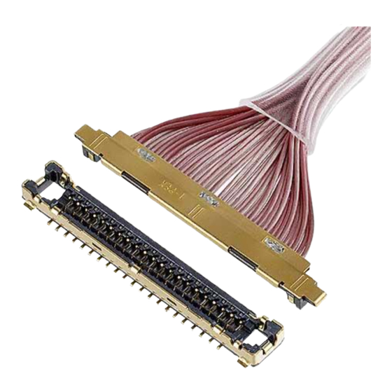
CABLINE
Part No. 20531
Assembly Manual
March 24, 2020
July 8, 2019
September 9, 2016
January 26, 2014
Date
-UX II PLUG
®
A.Koyanagi
A.Koyanagi
S.K
D.S
Prepared by
I-PEX Inc.
1 / 17
T.Kurachi
T.Kurachi
-
-
Checked by
QKE-DFFDE09-04 REV.8
Y.Shimada
H.Ikari
K.N
Tom
Approved by
Advertisement

Related Manuals for I-PEX CABLINE-UX II PLUG


Summary of Contents for I-PEX CABLINE-UX II PLUG
- Page 1 Assembly Manual S20185 March 24, 2020 A.Koyanagi T.Kurachi Y.Shimada S19431 July 8, 2019 A.Koyanagi T.Kurachi H.Ikari S16608 September 9, 2016 S14251 January 26, 2014 Rev. Date Prepared by Checked by Approved by Confidential C I-PEX Inc. QKE-DFFDE09-04 REV.8 1 / 17...
- Page 2 Document No. CABLINE-UX II PLUG Assembly Manual ASM-10001 1.目的 (Purpose): CABLINE UX II PLUG における、ケーブルの芯線半田付け手順及び Metal cover の組み付け手順について明記する。 This manual provides the soldering method of the cable’s center conductor and assembly method of Metal Cover to CABLINE UX II PLUG.
- Page 3 Document No. CABLINE-UX II PLUG Assembly Manual ASM-10001 3.2 パルスヒート条件[推奨] (Recommended pulse heat condition) ①アイドリング温度 (Idle temp.) 150℃ ②1 ヒート設定温度 (1 heat temp.) 220℃ ③ 〃 立ち上がり時間 ( 〃 rise time) 0.5sec. ④ 〃 維持時間 ( 〃 holding time) 3.0sec.
- Page 4 Document No. CABLINE-UX II PLUG Assembly Manual ASM-10001 4.作業手順 (Work procedures): 4-1. 芯線の半田付け (Soldering of center-conductor) ① まず適合ケーブルの端末処理形状を下図の様にして下さい。 First, process the cable end as shown below. 【Micro coax cable】 ・Cable Dimension Unit:mm Part No. 20531-030T-*2 3.50 7.50 8.50 20531-034T-*2 4.00 8.50...
- Page 5 Document No. CABLINE-UX II PLUG Assembly Manual ASM-10001 【Discrete cable】 ・Cable Dimension Unit:mm Part No. 20531-030T-*2 3.50 7.50 20531-034T-*2 4.00 8.50 20531-040T-*2 4.75 10.00 20531-050T-*2 6.00 12.50 φ0.102 AWG#39 Confidential C 5 / 17...
- Page 6 Document No. CABLINE-UX II PLUG Assembly Manual ASM-10001 ②コンタクトにフラックスを塗布して下さい。 Apply flux to contact. Applying flux area Photo.1 Applying flux area ③全コンタクトにフラックスが塗布されたことを確認して下さい。 Please confirm all contacts were applied flux. Photo.2 After applying flux ※Photo.3 のようにフラックスを塗布し過ぎないで下さい。フラックスの飛散及び フラックス過多による嵌合部への染み出しの原因となります。 ※Please do not apply flux too much like Photo.3. It can cause flux splash or leak to the mating area.
- Page 7 Document No. CABLINE-UX II PLUG Assembly Manual ASM-10001 ④コネクタに半田バー(Solder Bar)をセットする。 Place a solder bar at center of connector (HSG ASS’Y). Solder Bar Fig.1 Placing solder bar ⑤ケーブルをセットする。 Set the cable. Cable Fig.2 Setting cable Confidential C 7 / 17...
- Page 8 Document No. CABLINE-UX II PLUG Assembly Manual ASM-10001 ⑥芯線をパルスヒートにて半田付けする。 半田付け状態は、下記 Photo.4,5 参照。 Solder center conductors with a pulse heater. For soldering condition, see photo.4 and 5. Blank pin Photo.4 AWG#44 Photo.5 Expansion part Confidential C 8 / 17...
- Page 9 Document No. CABLINE-UX II PLUG Assembly Manual ASM-10001 ※極間が短絡または半田が溶け残ってしまった場合は(下記 Photo.7 参照) ヒーターチップを洗浄して再度パルスヒートにて加熱を行って下さい。 製品にダメージを与える恐れがある為、回数は 1 回だけです。 これで短絡が直らない場合は、NG 箇所のみ半田コテにて手修正して下さい。 Blank pin についても同様のご対応をお願いします。(Photo.4 参照) In case short circuit occurred or there was any unmelted solder (See photo.7 below), wash the heater tip and heat again with pulse heater only one time. (Several heating can damage the product.) If the short circuit can’t be repaired, use the soldering iron and repair it (NG point only).
- Page 10 Document No. CABLINE-UX II PLUG Assembly Manual ASM-10001 ※Discrete cable を使用する場合は、METAL COVER を取り付ける前に結線部に絶縁テープを貼りつけて下さい。 When using a discrete cable, please apply an insulating tape to the connection before assemble METAL COVER. Insulating tape HOUSING 及びケーブルのジャケットには掛からないようにお願いします。 METAL COVER の浮きが発生する可能性があります。 Please do not hang on HOUSING and cable jackets.
- Page 11 Document No. CABLINE-UX II PLUG Assembly Manual ASM-10001 4-2. METAL COVER 取り扱い注意事項 (Cautions in treating METAL COVER) METAL COVER はキャリア付きリール状態にて納品されます。 METAL COVER をキャリアから折り取る手順を明記します。 METAL COVER is delivered in the reel with a career. The following is the method to cut METAL COVER from Career.
- Page 12 Document No. CABLINE-UX II PLUG Assembly Manual ASM-10001 View A View B Without burrs Photo.13 After cut Plug Cover ノッチ部状態(Detail of Notch) Photo.14 Bottom side view Photo.15 Upper side view 注意:下写真(赤矢印)の様に無理やり引っ張ったりして切り離すとバリや変形の原因になります。 Caution: By pulling like a lower photo to cut off by force (Red arrow direction), burrs and transformation can be caused.
- Page 13 Document No. CABLINE-UX II PLUG Assembly Manual ASM-10001 4-3. Metal cover 組み付け (Assembly of Metal cover) ①Housing ass’y 正面側から housing ass’y 及び Plug Cover の○付け形状部を合わせ、Plug Cover の 両端のみを保持し青矢印方向にスライドして組み付ける。 (※部は変形の恐れがあるため組み付け時に力が掛からないよう注意願います) From the front side of the housing ass’y, align shapes of the housing ass’y and the plug cover circled in the following figure, then slide the both sides of plug cover in the direction of the blue arrow for assembly.
- Page 14 Document No. CABLINE-UX II PLUG Assembly Manual ASM-10001 ★ point ★ point Fig.6 Detail of ★point ※Housing insert shell のピンプルが Metal cover の穴の中央にはまっているかコネクタ底面から確認のこと。 From the connector bottom side, confirm whether the pimple of Housing insert shell fitted into center of the hole of Metal cover or not.
- Page 15 Document No. CABLINE-UX II PLUG Assembly Manual ASM-10001 4-4. ケーブル固定 (Cable fixation) ケーブル保護の為、ケーブル端末部を接着剤にて固定を推奨。 推奨接着剤 : LOCTITE 352 To protect the cable, it is recommended to fix the cable terminal part with bond. Recommended bond: LOCTITE 352 BONDING BONDING RANGE BONDING RANGE 1.50 MAX.
- Page 16 Document No. CABLINE-UX II PLUG Assembly Manual ASM-10001 5.開梱時及び梱包時の取り扱い注意及び手順(Cautions and methods in opening and closing the package ※ 製品を破損させる恐れがありますのでご注意ください (※ There is possibility to cause damage to products. Please pay attention.) ①最上面に畳まれている気泡緩衝材を開きます。 気泡緩衝材 AIR BUBBLE SHEET Unfold the folded AIR BUBBLE SHEET at the top.
- Page 17 Document No. CABLINE-UX II PLUG Assembly Manual ASM-10001 ④ゴムバンドの外し方 How to remove the rubber band. ※開梱時、トレーを挟み込んでいるゴムバンドを外す際の衝撃にご注意ください。 ※When opening the package, please pay attention not to apply shock to products by rubber band. 梱包時の注意(Cautions in closing the package) 製品の入っているトレーに再度トレーを重ねる際は、下側のトレーに入っている製品の向きにご注意ください。 (正常にポケット内に入っているかも併せてご確認お願いします) When piling a tray on another tray, please check the direction of the products in the lower tray.
Need help?
Do you have a question about the CABLINE-UX II PLUG and is the answer not in the manual?
Questions and answers