Advertisement
Quick Links
ASM-17005
Document No.
1
S19446
0
S17557
Rev.
ECN
Confidential C
CABLINE
Part No. 20846
Assembly Manual
July/22/'19
M.Nakamura
Aug./02/'17
Date
Prepared by
-VS II PLUG
®
T.Masunaga
K.Baba
Checked by
I-PEX Inc.
1 / 16
T.Kurachi
QKE-DFFDE09-04 REV.8
H.Ikari
Y.Shimada
Approved by
Advertisement

Related Manuals for I-PEX CABLINE-VS II PLUG


Summary of Contents for I-PEX CABLINE-VS II PLUG
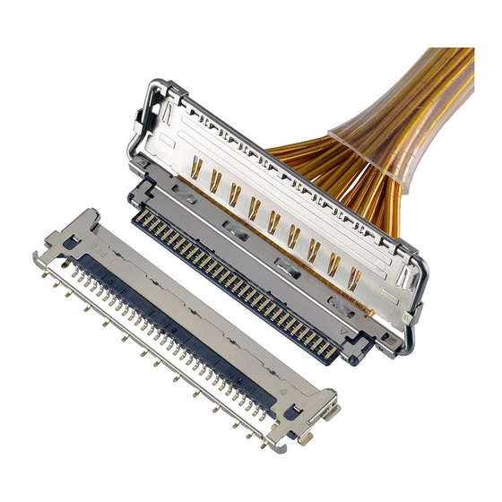
- Page 1 ASM-17005 Document No. CABLINE -VS II PLUG ® Part No. 20846 Assembly Manual S19446 July/22/’19 M.Nakamura T.Masunaga H.Ikari S17557 Aug./02/’17 K.Baba T.Kurachi Y.Shimada Rev. Date Prepared by Checked by Approved by Confidential C I-PEX Inc. QKE-DFFDE09-04 REV.8 1 / 16...
- Page 2 Document No. CABLINE-VS II PLUG Assembly Manual ASM-17005 1.Purpose: This manual is to explain the soldering method / process of the CABLINE-VS II PLUG with cable, and assembly of LOCK BAR ASS’Y, SHELL A. 2.Applicable connector: Name: CABLINE-VS II PLUG Parts No.:...
- Page 3 Document No. CABLINE-VS II PLUG Assembly Manual ASM-17005 4. Recommended pulse heat condition MICRO-COAX ①Idle temp. 150℃ ②1 heat temp. 220℃ ③ 〃 rise time 0.5sec. ④ 〃 holding time 3.0sec. ⑤2 heat temp. 300~320℃ ⑥ 〃 rise time 0.5sec.
- Page 4 Document No. CABLINE-VS II PLUG Assembly Manual ASM-17005 5.Work procedures: 5-1. Soldering of center-conductor ①The cables have to be fabricated as shown below in advance of soldering. Recommended MICRO-COAX CABLE dimension MICRO-COAX dimension MICRO-COAX AWG#** Confidential C 4 / 16...
- Page 5 Document No. CABLINE-VS II PLUG Assembly Manual ASM-17005 Recommended DISCRETE CABLE dimension DISCRETE dimension DISCRETE AWG#** Confidential C 5 / 16...
- Page 6 Document No. CABLINE-VS II PLUG Assembly Manual ASM-17005 ②Apply flux to contact by the dispenser etc., and please confirm all contacts were applied flux. Applying Flux area Photo.1 After applying flux ※Please do not apply flux too much like Photo.2. It can cause flux splash or leak to the mating area.
- Page 7 Document No. CABLINE-VS II PLUG Assembly Manual ASM-17005 ③Pre-set and locate solder bar at center of connector (HSG ASS’Y). Solder Bar Fig.1 Set of solder bar ④Set the cable. ※Setting discrete cable is to protect 0.2MAX. as Fig.3. There is danger that Center Conductor touch SHELL.
- Page 8 Document No. CABLINE-VS II PLUG Assembly Manual ASM-17005 ⑤Center-conductors are soldered with pulse heater. See photo.3 of soldering condition. Photo.3 AWG#40 Caution: The SHELL bottom side of PLUG HSG ASS'Y has convex shape at the points shown in Fig.4, so please make escape shape on the receiving jig of the pulse heater to prevent interference.
- Page 9 Document No. CABLINE-VS II PLUG Assembly Manual ASM-17005 Caution: Do not forcedly pull the cable toward red arrow direction after soldering or apply excessive load on the soldered area, or it may peel the solder. [Fig. 5] Fig.5 Cause of solder peeling ◆Insulating tape thickness t=0.06mm...
- Page 10 Document No. CABLINE-VS II PLUG Assembly Manual ASM-17005 5-2. Cautions in treating SHELL A SHELL A is delivered in the reel with a carrier. The following is the method to cut SHELL A from Carrier. ① Cut carrier on the cut line of the left below picture (green line) by a scissors for metal.
- Page 11 CABLINE-VS II PLUG Assembly Manual ASM-17005 5-3. Assembly of LOCK BAR ASS’Y LOCK BAR ASS’Y is assembled to HOUSING ASS’Y. ※I-PEX logo mark side of LOCK BAR ASS’Y facing the cable side. LOGO MARK LOCK BAR ASS’Y P/N:20848-0**T-01 Fig.6 Assembly of LOCK BAR ASS’Y 5-4.
- Page 12 Document No. CABLINE-VS II PLUG Assembly Manual ASM-17005 ②SHELL A is assembled from the upper side of HOUSING ASS’Y. Fig.8 Assembly of SHELL-A Confidential C 12 / 16...
- Page 13 Document No. CABLINE-VS II PLUG Assembly Manual ASM-17005 ③Confirms whether SHELL A is assembled properly. Whether SHELL locks are assembled properly. (Fig.9★ point) ★Point (Both sides) 135° ★Point (Both sides) Fig.9 The assembly confirmation of SHELL-A Confidential C 13 / 16...
- Page 14 Document No. CABLINE-VS II PLUG Assembly Manual ASM-17005 ④SHELL A, B and GND BAR are soldered with the soldering iron at all designated points. (Fig.10,12◆point) Refer to Fig.16 for a limit of the solder height. For conditions of Soldering iron refer to sheet 8.
- Page 15 Document No. CABLINE-VS II PLUG Assembly Manual ASM-17005 ◆Point Fig.12 Soldering of SHELL-B and GND BAR Fig.13 Solder leaking ⑤SHELL A and SHELL B are soldered with the soldering iron at all designated points. (Fig.14◆point) Conditions of Soldering iron refer to sheet 8.
- Page 16 Document No. CABLINE-VS II PLUG Assembly Manual ASM-17005 5-5. Cable fixation Fix the cable terminal part with the bond. Recommended Bond: LOCTITE 352 Fig.15 Bonding Fig.16 Soldering & Bonding Confidential C 16 / 16...
Need help?
Do you have a question about the CABLINE-VS II PLUG and is the answer not in the manual?
Questions and answers