Advertisement
Quick Links
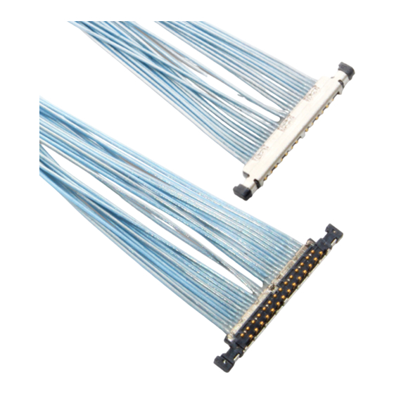
ASM-09004
Document No.
4
S19433
3
S18098
2
S17547
1
S12558
Rev.
ECN
Confidential C
CABLINE
Part No. 20496-#**-##
Assembly Manual
July 8, 2019
January 30, 2018
July 27, 2017
December 10, 2012
Date
-UA II PLUG
®
S.Yamaguchi
R.Hoshino
R.Hoshino
Y.Watanabe
Prepared by
I-PEX Inc.
1 / 14
T.Kurachi
K.Tanaka
K.Tanaka
K.Narita
Checked by
QKE-DFFDE09-04 REV.8
H.Ikari
M.Takemoto
M.Takemoto
T.Takano
Approved by
Advertisement

Related Manuals for I-PEX CABLINE-UA II PLUG


Summary of Contents for I-PEX CABLINE-UA II PLUG
- Page 1 T.Kurachi H.Ikari S18098 January 30, 2018 R.Hoshino K.Tanaka M.Takemoto S17547 July 27, 2017 R.Hoshino K.Tanaka M.Takemoto S12558 December 10, 2012 Y.Watanabe K.Narita T.Takano Rev. Date Prepared by Checked by Approved by Confidential C I-PEX Inc. QKE-DFFDE09-04 REV.8 1 / 14...
- Page 2 -UA II PLUG Assembly Manual ASM-09004 ® 1. 目的 (Purpose) CABLINE-UA II PLUG における、ケーブルの芯線半田付け手順及び METAL COVER の組み付け手順について明記する。 This manual provides the soldering method of the cable’s center conductor and assembly method of METAL COVER to CABLINE-UA II PLUG. 2. 適用コネクタ (Applicable connector)
- Page 3 Document No. CABLINE -UA II PLUG Assembly Manual ASM-09004 ® 3.2 パルスヒート条件[推奨] (Recommended pulse heat condition) ① アイドリング温度 (Idle temperature) 150 ℃ ② ヒート設定温度 heat temperature) 220 ℃ ③ 立ち上がり時間 rise time) 0.5 seconds ④ 維持時間 holding time) 3.0 seconds ⑤...
- Page 4 Document No. CABLINE -UA II PLUG Assembly Manual ASM-09004 ® 4.作業手順 (Work procedures): 4-1. 芯線の半田付け (Soldering of center-conductor) ① まず適合ケーブルの端末処理形状を下図の様にして下さい。 First, process the cable end as shown below. 【Micro coax cable】 (Unit:mm) ・Cable Dimension Unit: mm Part No. 20496-#26-## 20496-#32-## 10.8 20496-#40-## 12.3...
- Page 5 Document No. CABLINE -UA II PLUG Assembly Manual ASM-09004 ® 【Discrete cable】 (Unit:mm) ・Cable Dimension Unit: mm Part No. 20496-#26-## 20496-#32-## 10.8 20496-#40-## 12.3 13.2 20496-#50-## 15.3 16.2 AWG#39 0.102 Confidential C 5 / 14...
- Page 6 Document No. CABLINE -UA II PLUG Assembly Manual ASM-09004 ® ②コンタクトにフラックスを塗布して下さい。 Apply flux to contact. Applying flux area Photo 1 Applying flux area ③全コンタクトにフラックスが塗布されたことを確認して下さい。 Please confirm all contacts were applied flux. Pass Photo 2 After applying flux ※ Photo 3 のようにフラックスを塗布し過ぎないで下さい。フラックスの飛散及び フラックス過多による嵌合部への染み出しの原因となります。...
- Page 7 Document No. CABLINE -UA II PLUG Assembly Manual ASM-09004 ® ④コネクタに半田バー(Solder Bar)をセットする。 Place a solder bar at center of connector (HOUSING ASS’Y). Solder Bar Fig. 1 Placing solder bar ⑤ケーブルをセットする。 Set the cable. Cable Fig. 2 Setting cable (MCX) ※Discrete cable を使用する場合は、Jacket の先端と製品のリブの端が合うようにセットして下さい。 When using a discrete cable, set it so that the end of the jacket and the end of the product rib match.
- Page 8 Document No. CABLINE -UA II PLUG Assembly Manual ASM-09004 ® ⑥芯線をパルスヒートにて半田付けする。 半田付け状態は、下記 Photo 4, 5 参照。 Solder center conductors with a pulse heater. For soldering condition, see photo 4 and 5. Photo 4 AWG#44 Photo 5 Expansion part Confidential C 8 / 14...
- Page 9 Document No. CABLINE -UA II PLUG Assembly Manual ASM-09004 ® ※極間が短絡または半田が溶け残ってしまった場合は(下記 Photo 7 参照) ヒーターチップを洗浄して再度パルスヒートにて加熱を行って下さい。 製品にダメージを与える恐れがある為、回数は 1 回だけです。 これで短絡が直らない場合は、NG 箇所のみ半田コテにて手修正して下さい。 In case short circuit occurred or there was any unmelted solder (See photo 7 below), wash the heater tip and heat again with pulse heater only one time. (Several heating can damage the product.) If the short circuit can’t be repaired, use the soldering iron and repair it (Failed point only).
- Page 10 Document No. CABLINE -UA II PLUG Assembly Manual ASM-09004 ® 4-2. METAL COVER 取扱注意事項 (Cautions in treating METAL COVER) METAL COVER はキャリア付きリール状態にて納品されます。 METAL COVER をキャリアから折り取る手順を明記します。 METAL COVER is delivered in the reel with a carrier. The following is the method to cut Metal Cover from carrier. ①...
- Page 11 Document No. CABLINE -UA II PLUG Assembly Manual ASM-09004 ® Upper side Bottom side view View B View A Without burrs View A View B Photo 13 After cut METAL COVER ノッチ部状態(Detail of Notch) Photo 14 Bottom side view Photo 15 Upper side view 注意:下写真(赤矢印)の様に無理やり引っ張ったりして切り離すとバリや変形の原因になります。...
- Page 12 Document No. CABLINE -UA II PLUG Assembly Manual ASM-09004 ® 4-3. METAL COVER 組み付け (Assembly of METAL COVER) ①コネクタ上面側から Housing の4箇所のスリットに METAL COVER の爪4箇所を挿入して組み付ける。 Assemble METAL COVER by inserting four nails of Metal Cover into four slits of Housing from the upper side of the connector.
- Page 13 Document No. CABLINE -UA II PLUG Assembly Manual ASM-09004 ® ③ METAL COVER が正常に組み立てられているか確認する。 METAL COVER が HOUSING に挿入されているか。(Fig. 4 ★部 及び Photo 17 参照) Confirm whether METAL COVER is assembled properly or not. Confirm whether METAL COVER is inserted into Housing. (See Fig. 4 ★...
- Page 14 Document No. CABLINE -UA II PLUG Assembly Manual ASM-09004 ® ④ Metal Cover の表側 3 箇所を Ground Bar を半田コテにて半田付けする。(Fig. 5 ◆部) 半田の高さ(半田量)の限度は Fig. 6 を参照。 半田コテの条件は、8 頁参照。 Solder holes of METAL COVER 3 positions and Ground Bar with the soldering iron. (Fig. 5 ◆...
Need help?
Do you have a question about the CABLINE-UA II PLUG and is the answer not in the manual?
Questions and answers