Advertisement
Quick Links
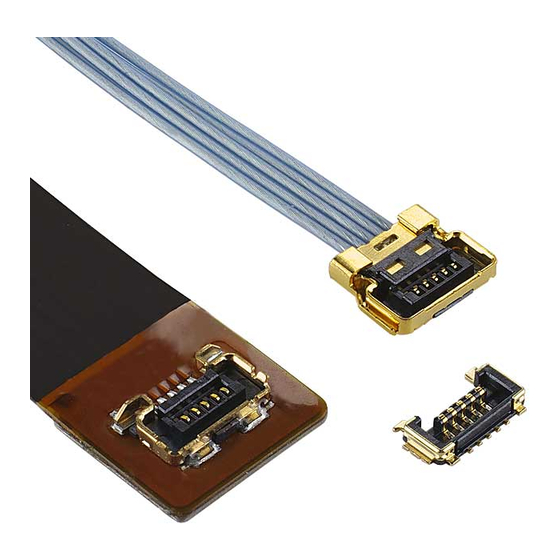
ASM-18002
Document No.
4
S20228
3
S20219
2
S20070
1
S20016
Rev.
ECN
Confidential C
CABLINE
Part No. 20857
Assembly Manual
April 21,2020
April 15,2020
February 20, 2020
January 15, 2020
Date
-UY PLUG
®
Y.Fukumoto
H.Takao
R.Takahashi
Y.Fukumoto
Prepared by
I-PEX Inc.
1 / 22
J.Tonai
Y.Fukumoto
T.Yamauchi
Checked by
QKE-DFFDE09-04 REV.8
T.Yamauchi
Y.Hashimoto
T.Yamauchi
Y.Shimada
Approved by
Advertisement

Related Manuals for I-PEX CABLINE-UY


Summary of Contents for I-PEX CABLINE-UY
- Page 1 April 21,2020 Y.Fukumoto T.Yamauchi S20219 April 15,2020 H.Takao J.Tonai Y.Hashimoto S20070 February 20, 2020 R.Takahashi Y.Fukumoto T.Yamauchi S20016 January 15, 2020 Y.Fukumoto T.Yamauchi Y.Shimada Rev. Date Prepared by Checked by Approved by Confidential C I-PEX Inc. QKE-DFFDE09-04 REV.8 1 / 22...
- Page 2 ASM-18002 1. 目的 (Purpose): CABLINE-UY PLUG における、ケーブルの半田付け手順及び SHELL A の組み付けについて明記する。 This manual is to explain the soldering method / process of the CABLINE-UY PLUG with cable, and assembly of SHELL A. 2. 適用コネクタ (Applicable connector): Name: CABLINE-UY PLUG Parts No. : Set P/N CABLE ASS’Y...
- Page 3 Document No. CABLINE-UY PLUG Assembly Manual ASM-18002 4. パルスヒート条件[推奨] (Recommended pulse heat condition) MICRO-COAX ①アイドリング温度 (Idle temp.) 150℃ ②1 ヒート設定温度 (1 heat temp.) 220℃ ③ 〃 立ち上がり時間 ( 〃 rise time) 0.5sec. ④ 〃 維持時間 ( 〃 holding time) 3.0sec.
- Page 4 Document No. CABLINE-UY PLUG Assembly Manual ASM-18002 5.作業手順 (Work procedures): 5-1. 芯線の半田付け (Soldering of center-conductor) ①まず適合ケーブルの端末処理形状を下図の様にして下さい。 The cables have to be fabricated as shown below in advance of soldering. ※C : 5Pin – 1.4 10Pin-3.15 Confidential C 4 / 22...
- Page 5 Document No. CABLINE-UY PLUG Assembly Manual ASM-18002 ※C : 5Pin – 1.4 10Pin-3.15 Confidential C 5 / 22...
- Page 6 Document No. CABLINE-UY PLUG Assembly Manual ASM-18002 ②ディスペンサー等でコンタクトにフラックスを塗布し、全コンタクトにフラックスが塗布されたことを確認して下さい。 Apply flux to contact by the dispenser etc., and please confirm all contacts were applied flux. Applying Flux area Pass Photo. 1 After applying flux ※Photo.2 のようにフラックスを塗布し過ぎないで下さい。 フラックスの飛散及びフラックス過多による嵌合部への染み出しの原因となります。 ※Please do not apply flux too much as shown in Photo.2. It may cause flux splash or leak to the mating area.
- Page 7 Document No. CABLINE-UY PLUG Assembly Manual ASM-18002 ③コネクタに半田バーをセットする。 Pre-set and locate solder bar at center of connector (HOUSING ASS’Y). Solder Bar Fig. 1 Set of solder bar ④ケーブルをセットする。 Set the cable. <注意事項/Caution> 芯線が Pad 上に収まっていること(Pad 中央部を超えていることが望ましい)。 Ground Bar がハウジングの GND BAR 収容部に収まっていること。...
- Page 8 Document No. CABLINE-UY PLUG Assembly Manual ASM-18002 芯線長が 5-1 で示した長さでないと正常にパルスヒートができない恐れがあります。 If the length of center conductor is not the length indicated in 5-1, pulse heat may not be performed normally. 芯線先端が Pad 中央より下回っている The tip of center conductor does not reach the center of Pad.
- Page 9 Document No. CABLINE-UY PLUG Assembly Manual ASM-18002 ⑤芯線をパルスヒートにて半田付けする。半田付け状態は、Photo.3 参照。 Center-conductors are soldered with pulse heater. See Photo.3 for soldering condition. Photo. 3 AWG#42 Photo. 4 短絡 NG/Short-circuit NG ※万が一、極間が短絡した場合(Photo.4 参照)は、再度パルスヒートにて加熱を行って下さい。 製品にダメージを与える恐れがある為、リワークの回数は 1 回として下さい。 これで短絡が直らない場合は、NG 箇所のみ半田コテにて手修正して下さい。 ※When solder bridge is appeared between the terminal, try heating again with pulse heater only one time.
- Page 10 Document No. CABLINE-UY PLUG Assembly Manual ASM-18002 ⑥Discrete cable 仕様については、半田付け部に UV 樹脂を塗布することを推奨する。 For Discrete cable specifications, it is recommended to apply UV resin to the soldered part BONDING LIMIT CRITERIA ボンディング限界基準 Bonding Photo.5 Discrete UV Apply resin Fig.4 Bonding Photo.6 UV Apply resin appearance OK Photo.7 UV Apply resin appearance NG...
- Page 11 Document No. CABLINE-UY PLUG Assembly Manual ASM-18002 6.SHELL A 圧着手順(SHELL A crimping procedure) 6-1. SHELL A 取扱注意事項 (Cautions in treating SHELL A) SHELL A はキャリア付きリール状態にて納品されます。SHELL A をキャリアから折り取る手順を明記します。 SHELL A is delivered in the reel with a carrier. The following is the method to cut SHELL A from Carrier.
- Page 12 Document No. CABLINE-UY PLUG Assembly Manual ASM-18002 注意:Photo. 13(赤矢印)の様に無理やり引っ張り切り離すとバリや変形の原因になります。 Caution: By pulling like the photo below to cut off by force (Red arrow direction), burrs and transformation can be caused. Photo. 13 Cut by force (Bad example) Confidential C 12 / 22...
- Page 13 Document No. CABLINE-UY PLUG Assembly Manual ASM-18002 6-2 SHELL A 圧着 JIG (SHELL A Crimping JIG) 91159-005 … 5pin JIG P/N 91159-010 … 10pin 外形寸法 (Outline dimension) : (W) 150[mm] × (D) 180[mm] ×(H) 310[mm] 重量 (Weight) 約 6.8[kg] Photo. 14 Crimping JIG 6-3.
- Page 14 Document No. CABLINE-UY PLUG Assembly Manual ASM-18002 ② Sheet 8 にてはんだ付けした HSG ASS’Y を結線側が下、ケーブルが手前になるように SHELL A に組み付ける。(photo16) Assemble the HSG ASS’Y to SHELL A so that crimping side shall be below and cable shall be front. (Photo 16) Photo. 16 Setting HSG ASS’Y HSG ASS’Y を...
- Page 15 Document No. CABLINE-UY PLUG Assembly Manual ASM-18002 Setting position OK Setting position NG A A Photo. 18 Setting position NG Photo. 17 Setting position OK Fig.7 SECT B-B Fig.6 SECT A-A HSG ASS’Y が SHELL A に乗り上げている 上記の状態で圧着を行うと HSG が破壊されますのでご注...
- Page 16 ●治具のお手入れは、定期的に製品に関わる部分に付着しているケーブル切り屑等をブラシ、エアー等にて 必ず清掃して下さい。又、摺動部にはミシン油か市販の防錆油を塗布してから保管して下さい。 ●This Semi Auto machine is a jig for harnessing I-PEX CABLINE-UY(P/N:3568-0**1) to a specially processed coaxial cable. Therefore, non- specified connectors and cables are not allowed. Failure to do so may damage the jig. ●With the exception of the specified replacement area, loosen or removing bolts are prohibited. Modifying is prohibited to avoid the defect of the jig.
- Page 17 Document No. CABLINE-UY PLUG Assembly Manual ASM-18002 7. 外観検査(Appearance inspection) 製品が正しく結線、圧着されているか確認する。 Make sure that the product is properly wired and crimped. SHELL A のスリットから HSG ASS’Y が 見えること HSG ASS’Y にダメージなき事 HSG ASS’Y shall be seen from the slit HSG ASS’Y shall not be damaged of SHELL A.
- Page 18 Document No. CABLINE-UY PLUG Assembly Manual ASM-18002 7-2. HSG ASS’Y Setting NG HSG ASS’Y の結線側を上(裏表が逆状態)にして結線している Crimped in the condition that crimping side of HSG ASS’Y was set to top. SHELL A のスリットに HSG ASS’Y がセットされていない HSG ASS’Y shall be seen from the slit of SHELL A.
- Page 19 Document No. CABLINE-UY PLUG Assembly Manual ASM-18002 8. SHELL A と GND BAR を半田コテにて半田付けする。 (Fig.8◆部) 半田コテの条件は、8 頁参照。 SHELL A and GND BAR are soldered with the soldering iron at designated points. (Fig.8◆point) For conditions of Soldering iron refer to sheet 8.
- Page 20 Document No. CABLINE-UY PLUG Assembly Manual ASM-18002 8-1. SHELLA と GND BAR のはんだ付け外観 OK / NG Soldering of SHELL A and GND BAR appearance OK/NG Photo. 30 Soldering of SHELL A and GND BAR appearance OK Photo. 31 Soldering of SHELL A and GND BAR appearance NG Photo.
- Page 21 Document No. CABLINE-UY PLUG Assembly Manual ASM-18002 9. ケーブル固定(Cable fixation) ケーブル端末部を接着剤にて固定することを推奨する。 接着剤:LOCTITE 352 Fixing the cable terminal part with the bond is recommended. Bond:LOCTITE 352 BONDING LIMIT CRITERIA ボンディング限界基準 Fig.10 Bonding ●ボンディングは限界基準を超えないで下さい。 ●Bonding 塗布後、直ちに露光し凝固してください。放置すると接着剤がコネクタ内部に浸透し不具合の原因となります。 ●Bonding shall not exceed the limit criteria.
- Page 22 Document No. CABLINE-UY PLUG Assembly Manual ASM-18002 10. 完成品 外観例 (Finished product appearance example.) MICRO-COAX CABLE Photo. 38 Finished product appearance OK DISCRETE CABLE Photo. 39 Finished product appearance OK Confidential C 22 / 22...
Need help?
Do you have a question about the CABLINE-UY and is the answer not in the manual?
Questions and answers