Regency Fireplace Products City Series ACV40ENG Owners & Installation Manual
Zero clearance direct flue gas fireplace
Hide thumbs
Also See for City Series ACV40ENG:
- Owners & installation manual (87 pages) ,
- Owners & installation manual (15 pages) ,
- Owners & installation manual (84 pages)
Table of Contents
Advertisement
Quick Links
Zero Clearance Direct Flue Gas Fireplace
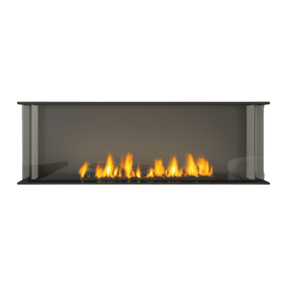
STYLE
Three sided
Warning
Fire or explosion Hazard
failure to follow safety warnings exactly could result in serious
injury, death, or property damage.
- Do not store or use gasoline or other flammable vapors and liquids in the vicinity of this or any other
appliance.
- WHAT TO DO IF YOU SMELL GAS
•
Do not try to light any appliance.
• Do not touch any electrical switch: do not use any phone in your building.
Leave the building immediately.
• Immediately call your gas supplier from a neighbour's phone. Follow the gas supplier's
instructions.
• If you cannot reach your gas supplier, call the fire department.
- Installation and service must be performed by a qualified installer, service agency or the gas supplier.
920-121
City Series
MODEL
ACB40ENG / ACB40ELP / ACB40EULPG
Installer: Please complete the details on the back cover
and leave this manual with the homeowner.
Homeowner: Please keep these instructions for future reference.
®
Owners &
Installation Manual
LISTINGS AND CODE APPROVALS
These gas appliances have been
tested in accordance with AS/NZS
5263.0 & AS/NZS 5263.1.8:2016
and have been certified by IAPMO for
installation and operation as described
in these Installation and Operating
Instructions.
Must be installed as per AS/NZS5601.
Your unit should be serviced
annually by an authorised service
person.
www.regency-fire.com.au
PRIMARILY A DECORATIVE AND NOT A
HEATING APPLIANCE.
DO NOT MODIFY THIS APPLIANCE.
03.12.20
Advertisement
Table of Contents

Subscribe to Our Youtube Channel
Related Manuals for Regency Fireplace Products City Series ACV40ENG


Summary of Contents for Regency Fireplace Products City Series ACV40ENG
- Page 1 City Series ® Owners & Zero Clearance Direct Flue Gas Fireplace Installation Manual LISTINGS AND CODE APPROVALS These gas appliances have been tested in accordance with AS/NZS 5263.0 & AS/NZS 5263.1.8:2016 and have been certified by IAPMO for installation and operation as described in these Installation and Operating Instructions. Must be installed as per AS/NZS5601. Your unit should be serviced annually by an authorised service person.
-
Page 2: Safety Decal
safety decal This is a copy of the label that accompanies Direct Flue Gas Fireplace. We have printed a copy of the contents here for your review. The safety label is located on the front inside base of the unit, visible when the outer front panel is removed. NOTE: Regency units are constantly being improved. Check ® the label on the unit and if there is a difference, the label on the unit is the correct one. Copy of Data Badge Regency Gas Fireplace Distributed by: Propane ULPG Gas Type Western Australia: Air Group Australia ACV40ENG ACV40ELP ACV40EULPG Model 28 Division St Welshpool, WA 6106 ACB40ENG ACB40ELP ACB40EULPG Eastern Australia... - Page 3 dimensions Dimensions Note: Height Dimension may vary depending on the height of the leveling legs. Note: These units are non-load bearing. City Series ACB40E |...
- Page 4 installation Clearances Flue Clearances to Combustibles Clearance: 3 sided Dimension Measured From: Horizontal - Top 76mm A: From Floor Min. 0mm Bottom of Fireplace Opening Horizontal - Side 51mm A1 : Mantel Height (min.) Top of Fireplace Opening Horizontal - Bottom 51mm B: Sidewall (on one side) 216mm Side of Fireplace Opening Vertical 51mm C: Enclosure Width (min.) 1230mm Minimum inside dimensions Passing through wall/ floor/ceiling - when 38mm D: Mantel Depth (max.) firestop is used. E: Alcove Width 2134mm Side wall to side wall (min.)
-
Page 5: Installation
installation Clearances Floor to ceiling with top opening Low framing with flues in front/sides or top Full framing with low flues in front or sides Full framing with flues in front or sides | City Series ACB40E... -
Page 6: Mantel Leg Clearances
installation Mantel Clearances Combustible mantel clearances from top of front facing are shown in the diagram on the right. 13mm Plasterboard, timber, timber panel, etc. 305mm 229mm 130mm Top of Bottomof Fireplace Fireplace Opening Opening 383mm Mantel Leg Clearances Combustible mantel leg clearances as per diagram: MANTEL LEG 216mm City Series ACB40E |... -
Page 7: Framing Dimensions
installation Framing Dimensions NOTE: Framing may be constructed of combustible material (ie. 51x102mm) and does not require steel studs. Two (2) optional steel stud kits may also be purchased. These kits may be used in place of the conventional wood framing as shown below. It comes as a compact kit (flush to the appliance on all sides)or an extended kit. The extended kit protrudes beyond each side of the appliance as shown on the front cover of this manual. There is also an optional hearth kit which may be purchased as shown on the front cover of this manual. These kits are highly recommended as it was designed specifically for the product to facilitate ease of installation. See instructions in this manual for details. Framing Description ACB40E Dimensions Framing Height 949mm Framing Width 1232mm Framing Depth 483mm Minimum Height to Combustibles 1600mm Flue Centerline Height 1429mm Gas Connection Opening Height 51mm Gas Connection Height 106mm Gas Connection Inset 330mm Gas Connection Opening Width 89mm Note: A combined minimum of 774 square centimetres of open area is required for the convection air outlet to cool the enclosure. Ensure clearances for Convection Air Outlets are met. See clearances ACB40E (3 sided) in this manual as there are different methods as to how this can be achieved. Note: Only basic framing dimensions are shown. The framing may also extend beyond the appliance on either side and also extend out front if a hearth is desired. See clearance/finishing requirements for details. Note: Unit is not load bearing. All finished materials must be supported by framing. Maximum mate- rial dimensions 51mm x 102mm for Header studs (installed on edge and flat) Note: This appliance must be installed on a solid surface such as a plywood floor... -
Page 8: Maximum Tv Recess
installation TV Recessed into Wall - Typical Installs Maximum TV Recess TV Flush with Hearth ACB40E shown ACB40E shown City Series ACB40E |... -
Page 9: Flueing Introduction
installation Flueing Introduction The ACB40E uses the "balanced flue" technology Co-Axial system. The inner liner flues products of combustion to the outside while the outer liner draws outside combustion air into the combustion chamber thereby eliminating the need to use heated room air for combustion and losing warm room air up the chimney. Note: These flue pipes must not be connected to any other appliance. The gas appliance and flue system must be flueed directly to the outside of the building, and never be attached to a chimney serving a separate solid fuel or gas burning appliance. Each direct flue gas appliance must use it's own separate flue system. Common flue systems are prohibited. Flueing Arrangement for Horizontal Terminations The diagram shows all allowable combinations of vertical runs with horizontal terminations, using one 90 (two 45 elbows equal one 90 elbow). Note: Must use optional rigid pipe adapter (Part# 510-994) when using Rigid Pipe Flueing Systems. (Metres) 1429mm "THIS UNIT MUST ALWAYS TERMINATE / FLUE DIRECTLY TO THE OUTDOORS." Flue RESTRICTOR SETTING: Flue restrictor factory set at Set 0. Refer to the "Flue Restrictor Position" section for details on how to change the flue restrictor from the factory setting of Set 0 to Set 2 if required. -
Page 10: Flueing Arrangements Horizontal Terminations
installation Flueing Arrangements Horizontal Terminations Flex Vent 102mm x 173mm These flueing systems, in combination with the ACV40E Direct Vent Gas Fireplace, have been tested and listed as a direct vent heater system. The location of the termination cap must conform to the requirements in the Vent Terminal Locations diagram in "Exterior Vent Termination Locations" section. Regency Direct Vent (Flex) System Termination Kits includes all the parts needed to install the ACV40E using a flexible vent. ® FPI Kit # Length Contains: #946-515 1.2m 175mm flexible outer liner (Kit length) 102mm flexible inner liner (Kit length) spring spacers... -
Page 11: Horizontal Terminations
installation Horizontal Terminations Rigid Pipe 102mm x 175mm The minimum components required for a basic horizontal termination are: 1 Horizontal Termination Cap 1 Rigid Pipe Adaptor (510-994) Horizontal 1 Wall Thimble Termination Cap 1 Length of pipe to suit wall thickness (see chart) Vinyl Siding Wall thickness is measured from the back standoffs to the inside mounting surface of termination cap. For siding other than vinyl Standoff (Optional) furring strips may be used, instead of the vinyl siding standoff, to create a level surface to mount the flue terminal. The Terminal must not be recessed into siding. Measure the wall thickness including furring strips. - Page 12 installation Horizontal Terminations Rigid Pipe 102mm x 175mm The diagrams below shows examples of horizontal termination arrangements using one, two, or three 90 elbows (two 45 elbows equal one 90 elbow) 1. A maximum of three 90 elbows are permitted. 2. Minimum distance between elbows is 305mm. • Maintain clearances to combustibles as listed in the "Clearances" section. • Horizontal flue must be supported every 0.9m. • Firestops are required at each floor level and whenever passing through a wall. • Must use optional rigid pipe adaptor (Part# 510-994) when using rigid pipe flue systems. • A flue guard should be used whenever the termination is lower than the specified minimum or as per local codes. • Flex system can only be used up to 3m - otherwise rigid flueing must be used. Horizontal Flueing with Two (2) 90 Elbows Horizontal Flueing with Three (3) 90 Elbows One 90 elbow = Two 45...
- Page 13 installation Flueing Arrangement for Vertical Terminations Vertical Flueing with Straight Vertical Flueing and or with a max. of two (2) 90 Elbows (1 - 90 2 - 45 The shaded area in the diagram shows all allowable combinations of straight vertical and offset to vertical terminations, using two elbows, with Rigid Pipe Flueing Systems. Two 45 elbows equal to one 90 elbow. • Vent must be supported at offsets. • Minimum distance between elbows is 305mm. • Maintain clearances to combustibles as listed in the "Clearances" section.
-
Page 14: Vertical Terminations
installation Vertical Terminations Rigid Pipe 102mm x 175mm The minimum components required for a basic vertical Vertical Terminal termination are: 1 Vertical Termination Cap 1 Rigid Pipe Adaptor (510-994) 1 Ceiling Firestop 1 Flashing Storm Collar 1 Storm Collar 1 Length of pipe to suit wall thickness (see chart) Flashing Galvanized pipe is desirable above the roofline due to its higher corrosion resistance. Continue to add pipe sections through the flashing until the height of the flue cap meets the minimum height Ceiling Firestop requirements specified in table below or local codes. Note that for steep roof pitches, the vertical height must be increased. A poor draft, or down drafting can result from high wind conditions... - Page 15 installation Vertical Terminations Rigid Pipe 102mm x 175mm • Two 45 elbows equal to one 90 elbow. Maximum of six 45 elbows allowed. • Flue must be supported at offsets. • Minimum distance between elbows is 305mm. • Maintain clearances to combustibles as listed in the "Clearances" section. • Horizontal flue must be supported every 0.9m. • Firestops are required at each floor level and whenever passing through a wall. • Must use optional rigid pipe adaptor (Part# 510-994 when using rigid pipe flue systems) Vertical Flueing with Three (3) 90 Elbows One 90 elbow = Two 45 elbows. Option H + H1 V + V1 With these options,...
Need help?
Do you have a question about the City Series ACV40ENG and is the answer not in the manual?
Questions and answers