Table of Contents
Advertisement
Quick Links
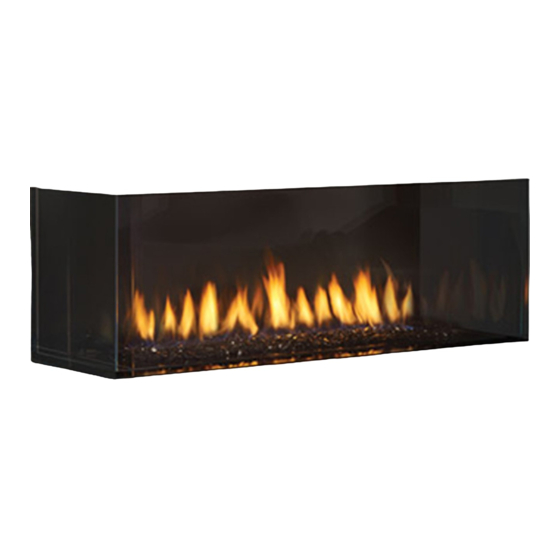
CC40LE-12 / CC40RE-12 Direct Vent
STYLE
Left Corner
Right Corner
Warning
Fire or explosion Hazard
failure to follow safety warnings exactly could result in serious
injury, death, or property damage.
- Do not store or use gasoline or other flammable vapors and liquids in the vicinity of this or any
other appliance.
- WHAT TO DO IF YOU SMELL GAS
•
Do not try to light any appliance.
• Do not touch any electrical switch: do not use any phone in your building.
Leave the building immediately.
• Immediately call your gas supplier from a neighbour's phone. Follow the gas supplier's
instructions.
• If you cannot reach your gas supplier, call the fire department.
- Installation and service must be performed by a qualified installer, service agency or the gas supplier.
Tested by:
Certified to/Certifié pour: CSA 2.17-2017
FPI FIREPLACE PRODUCTS INTERNATIONAL LTD. 6988 Venture St., Delta, BC Canada, V4G 1H4
920-559
City Series
®
MODEL
CC40LE-NG12 / CC40LE-LP12
CC40RE-NG12 / CC40RE-LP12
ANSI Z21.88-2019
CSA 2.33-2019
Installer: Please complete the details on the back cover
and leave this manual with the homeowner.
Homeowner: Please keep these instructions for future reference.
Owners &
Installation Manual
www.regency-fire.com
08.04.22
Advertisement
Table of Contents

Related Manuals for Regency Fireplace Products City Series CC40LE-NG12


Summary of Contents for Regency Fireplace Products City Series CC40LE-NG12
- Page 1 City Series ® Owners & CC40LE-12 / CC40RE-12 Direct Vent Installation Manual www.regency-fire.com STYLE MODEL Left Corner CC40LE-NG12 / CC40LE-LP12 Right Corner CC40RE-NG12 / CC40RE-LP12 Warning Fire or explosion Hazard failure to follow safety warnings exactly could result in serious injury, death, or property damage.
- Page 2 To the New Owner: Congratulations! You are the owner of a state-of-the-art Gas Fireplace by REGENCY . The City Series are hand crafted appliances and have ® been designed to provide you with all the warmth and charm of a wood fireplace at the flick of a switch. The CC40LE / CC40RE City Series have been approved by Intertek for both safety and efficiency.
- Page 3 MANUFACTURED MOBILE HOME REQUIREMENTS INFORMATION FOR MOBILE/MANUFACTURED HOMES AFTER FIRST SALE This Regency product has been tested and listed by Warnock Hersey/Intertek as a Direct Vent Wall Furnace to the following standards: ® VENTED GAS FIREPLACE HEATERS ANSI Z21.88-2019 / CSA 2.33-2019 and GAS-FIRED APPLIANCES FOR USE AT HIGH ALTITUDES CSA 2.17-2017.
- Page 4 WARNING CARBON MONOXIDE POISONING HAZARD Failure to follow the steps outlined below for each appliance connected to the venting system being placed into operation could result in carbon monoxide poisoning or death. The following steps shall be followed for each appliance connected to the venting system being placed into operation, while all other appliances connected to the venting system are not in operation: 1.
-
Page 5: Table Of Contents
table of contents Owner's Information Vertical Flue Extension Kit (Part #946-756) ........67 Ceiling Firestop / Firestop Spacer (Part #946-757) ......67 Copy of Safety Decal ..............6 CC40LE/CC40RE-11 NG System Data ..........68 Decal Location ................6 CC40LE/CC40RE-11 LP System Data ..........68 Dimensions (Left Corner) ............... -
Page 6: Copy Of Safety Decal
safety decal This is a copy of the label that accompanies Direct Vent Gas Fireplace. We have printed a copy of the contents here for your review. The safety label is located on the front inside base of the unit, visible when the outer front panel is removed. NOTE: Regency units are constantly being improved. -
Page 7: Dimensions (Left Corner)
dimensions Dimensions (Left Corner) " 1203mm " " 616mm 587mm " " 448mm 97mm GAS LINE INPUT AREA " 4" 102mm 172mm 48" " 1219mm 475mm " " 449mm 1109mm " " 375mm 1089mm Note: Electrical connection on left hand side of the appliance. A metal receptacle box is supplied/installed with the appliance to make all 120 volt electrical connections. -
Page 8: Dimensions (Right Corner)
dimensions Dimensions (Right Corner) " 1203mm " " 616mm 587mm " " 448mm 98mm GAS LINE INPUT AREA 4" " " 102mm 172mm 475mm " " 448mm 1108mm " 43" 1091mm 374mm Note: Height Dimension may vary depending on the height of the leveling legs. Dimensions will appear as (inches)"... -
Page 9: Gas Installation Checklist
dimensions Gas Installation Checklist REGENCY GAS INSTALLATION CHECKLIST This general checklist does not contain all pertinent installation details or specifics and does not supersede the guidelines in this manual. Your Regency dealer/installer should use it in conjunction with manual instructions. Please follow all local codes and jurisdictions in authority. Customer: Date Installed: Install Address:... - Page 10 installation REGENCY GAS INSTALLATION CHECKLIST Finishing If applicable, is only noncombustible material installed in the noncombustible areas? Do clearances meet installation and manual requirements? Do the mantels and/or projections comply with the installation manual? If applicable, was the solid fuel fireplace warning plate installed? Appliance Media Setup Do commands from the remote or wall switch light the pilot and main burner? Are the burner media/log set, glass door, and screen installed per instructions in the manual?
-
Page 11: Important Message
owner's information Important Message WE RECOMMEND REMOVING THE CHILDREN AND ADULTS SHOULD SAVE THESE INSTRUCTIONS GLASS WITH THE GLASS VACUUM BE ALERTED TO THE HAZARDS OF H O L D E R S S U P P L I E D B Y T H E HIGH SURFACE TEMPERATURES, City Series Direct Vent Fireplaces must be installed MANUFACTURER. -
Page 12: General Safety Information
owner's information General Safety Information 1. The appliance installation must conform with local codes or, in the absence of local codes, with the current Canadian or National Gas Codes, CAN1-B149 or ANSI Z223.1 Installation Codes. 2. See general construction and assembly instructions. -
Page 13: Lighting Procedure
owner's information Lighting Procedure The remote control system supplied has several options The first try for ignition will last approximately 60 seconds. If there is no flame ignition (rectification), the board will stop sparking for ap- for starting/operating the appliance using the battery proximately 35 seconds. -
Page 14: Copy Of The Lighting Plate Instructions
owner's information Copy of the Lighting Plate Instructions FOR YOUR SAFETY READ BEFORE LIGHTING POUR VOTRE SÉCURITÉ – À LIRE AVANT LA MISE EN MARCHE WARNING: If you do not follow these instructions exactly, a fire or explosion may result causing property damage, personal injury or loss of life. -
Page 15: Proflame Ii Remote Control Operating Instructions
owner's information Proflame II Remote Control Operating Instructions The transmitter and IFC are radio frequency devices. The Proflame Transmitter 2 is an integrated part of the Proflame 2 System, which consists of these elements: • Proflame 2 Transmitter, in conjunction with •... - Page 16 owner's information Temperature indication Display Remote-Flame Control With the system in the "OFF" position, press the Thermostat Key and the The Proflame has six (6) flame levels. With the system on, and the flame Mode Key at the same time. Look at the LCD screen on the transmitter level at the maximum in the appliance, pressing the Down Arrow Key to verify that a C or F is visible to the right of the room temperature once will reduce the flame height by one step until the flame is turned off.
- Page 17 owner's information Smart Thermostat (Transmitter Operation) Remote dimmer control (Light)** The auxiliary function controls the AUX power outlet by the dimmable The Smart Thermostat function adjusts the flame height in accordance light control. To activate this function use the Mode Key (fig. 1) to index to the difference between the set point temperature and the actual room to the AUX icon (fig.
- Page 18 owner's information Continuous Pilot/Intermittent Pilot (CPI/IPI) 5. "Clr" will remove a mode—use the up or down arrow while holding selection down ON/OFF and MODE (mode icon will disappear once removed). 6. Use the "MODE" button to move to the next function. Note: Power vent models do not have a Continu- 7.
-
Page 19: Proflame Ii Battery Holder Battery Replacement
owner's information Proflame II Battery Holder Battery Replacement & Battery Pack up if 120 Volt Power is lost IMPORTANT Non-Power Vent Model: Install the 4 AA batteries during power outages to run the main burner. However, the lights will not operate Battery Holder Battery Replacement &... -
Page 20: Wifi Dongle Installation (Optional)
CITY SERIES 40 owner's information WIFI Dongle Installation (Optional) WIFI Dongle Installation Instructions 1. Remove the safety glass and firebox glass – see manual. 5. Line up the tabs on the dongle with the notches on the IFC connection and insert the cable into the connection. 2. Remove the front lower firebox glass pad to allow access to the IFC cover. 6. Apply Velcro strips to the bottom of the dongle and to the side of the IFC bracket. 3. Locate the 2 screws on the IFC cover and remove the cover to access the IFC. 7. Place the dongle onto the IFC bracket. 4. Locate the WIFI dongle connection (X0A) on the side of the IFC. 8. Reverse steps 1, 2 and 3. | City Series CC40E-12 06.29.22 920-561... -
Page 21: Outer Safety Glass Panel (Barrier Glass) Installation / Removal
owner's information Outer Safety Glass Panel (Barrier Glass) Installation / Removal To watch the safety barrier glass installation video click here http://bit.ly/2ryq0c0 Note: safety glass panels must be installed to operate fireplace 1. Carefully remove glass safety panels from packaging. 3. - Page 22 owner's information Outer Safety Glass Panel (Barrier Glass) Installation / Removal Note: safety glass panels must be installed to operate fireplace. as shown in the diagram below. Note: After the side panel has been adjusted so it is installed at 90º to the 4.
-
Page 23: Inner Glass Panel (Firebox Glass) Installation / Removal
owner's information Inner Glass Panel (Firebox Glass) Installation / Removal To watch the firebox installation video click here http://bit.ly/2qfQwST Note: glass panels must be installed to operate fireplace Push side WARNING: GLASS HANDLING glass panel firmly to back We recommend using the glass vacuum holders supplied by the manufac- wall until turer. - Page 24 owner's information 5. Ensure all 7 front clamps are in the open position to allow clearance for Note: Ensure that the front glass is centered and evenly spaced with side tooltip the glass. glass (3 sided unit) - open to release glass clamps to remove from surface of glass.
-
Page 25: Maintenance Instructions
owner's information Maintenance Instructions Glass Replacement by having excessive lateral runs, too many elbows, and exterior portions of the system being exposed to cold weather. 1. Always turn off the gas valve before cleaning. In the event that you break your glass by impact, purchase your replacement from an authorized For relighting, refer to lighting instructions. - Page 26 requirements MA Code - CO Detector (for the State of Massachusetts only) 5.08: Modifications to NFPA-54, Chapter 10 (2) Revise 10.8.3 by adding the following additional requirements: (a) For all side wall horizontally vented gas fueled equipment installed in every dwelling, building or structure used in whole or in part for residential purposes, including those owned or operated by the Commonwealth and where the side wall exhaust vent termination is less than seven (7) feet above finished grade in the area of the venting, including but not limited to decks and porches, the following requirements shall be satisfied:...
-
Page 27: Installer's Information
requirements installer's information Locating Your Gas Fireplace Unit Assembly Prior to Installation Before you start 1. When selecting a location for your fireplace, ensure that the clearances are met. The CC40LE/CC40RE has 4 standoffs, 2 on one side and 2 at the back that need assembly before 2. -
Page 28: Installation Checklist
installer's information Installation Checklist This includes: 1. Clocking the appliance to ensure the correct 1. Locate appliance. Refer to the following firing rate (rate noted on label 28,500 Btu/h sections: NG/LP) after burning appliance for 15 minutes. a) Locating Your Fireplace b) Clearances 2. -
Page 29: Nailing Strips
tooltip installation Nailing Strips Nailing strips are shipped folded flat against the unit. Fold nailing strips out 90º before installing unit. Secure nailing strips to framing using wood or metal screws. Side nailing strip CC40RE tooltip Side nailing strip CC40LE Top nailing strip Top Nailing Strip Nailing strip is shipped with the appliance and will... -
Page 30: Ventilation Openings
installer's information Ventilation Openings Regency's patented Cool Wall system releases warmth at ceiling level. This system reduces excessive radiant heat in front of the fireplace so you can enjoy your fireplace more often. • Design your own chase vent solution to suit your home •... -
Page 31: Chase Enclosure
requirements installer's information Opening for vent Chase Enclosure 4”-4.5” (102 mm x 114 mm) When choosing to install the ventilation openings from the front or both sides, The top of the ventilation opening cannot be any lower than 0-3" from the top of the chase enclosure for all installations. -
Page 32: Clearances
installation Clearances The clearances listed below are minimum distances unless otherwise stated: A major cause of chimney related fires is failure to maintain required clearances (air space) to combustible materials. It is of the greatest importance that this fireplace and vent system be installed only in accordance with these instructions. Note: CC40LE shown in illustration. - Page 33 installation Clearances Lo w framing with vents Low framing with vents in front/sides or top Note: Ventilation opening may never be on one side only. CC40LE shown Width of chase x height from top of chase to ceiling must be no less than 120 square inches.
- Page 34 installation Clearances Chase enclosed Full framing with low vents in front or side/front Note: Ventilation opening may never be on one side only. CC40LE shown CC40LE shown Full framing with vents in front or sides | City Series CC40E-12...
-
Page 35: Mantel Clearances
installation Mantel Clearances Combustible mantel clearances from top of front facing are shown in the diagram on the right. 1/2" (13 mm) Drywall, wood, wood panel, etc. 12" (305 mm) 9" (229 m) 5-1/8" (130 mm) Top of Bottomof Fireplace Fireplace Opening 15-1/16”... -
Page 36: Framing Dimensions (Left Corner)
installation Framing Dimensions (Left Corner) NOTE: Framing may be constructed of combustible material (ie. 2 x 4) and does not require steel studs. Note: A combined minimum of Framing 120 square inches of open area Description CC40LE Dimensions is required for the convection air outlet to cool the enclosure. -
Page 37: Framing Dimensions (Right Corner)
installation Framing Dimensions (Right Corner) NOTE: Framing may be constructed of combustible material (ie. 2 x 4)and does not require steel studs. Framing Description CC40RE Dimensions Framing Height 37-3/8” (949mm) Framing Width 48-1/4" (1226mm) Framing Depth 19" (483mm) Note: A combined minimum of 120 square inches of open area Unit Base to Top Enclosure (Min.) 63"(1600mm) -
Page 38: Optional Flush Front Chase Vent Installation (Part # 657-991)
installation Optional Flush Front Chase Vent Installation - Part #657-991 (White) C40 Chase Vent Framing Clearances This optional flush front chase vent grill is designed so that only the grills are exposed. The 4 flanges in front which secure the chase vent grill to the stud work are covered by the drywall to give a seamless look. - Page 39 installation C40 Chase Vent Finish Detail Finish edges of drywall with trim or corner bead. Edge finish must not decrease opening area below 130in (3.25" x 40") or (83 mm x 1016 mm) City Series CC40E-12 |...
- Page 40 installation C40 Chase Vent Installation Example Frame opening for vent Screw Chase vent to Framing Use at least 3 sets of screws (See Vent Framing Clearances Page) to keep the vent at against framing Drywall Frame wall with nishing material If necessary, mark where the Cut hole in nishing material chase vent is located before...
-
Page 41: Optional Front Grill Installation (Part # 656-991)
installation Optional Front Grill Installation - Part #656-991 (Black) This optional grill meets the requirement of the 120 square inches required for the enclosure in all installations and is designed to keep the enclosure cool. In this application, both the flange and screws to secure the grills are exposed as this grill is designed to be installed after the finished facing has been placed on the wall. -
Page 42: Wall Board/Drywall Installation
installation Wall Board/Drywall Installation WARNING! Risk of Fire! Comply with all minimum clearances to combustibles as specified. Finishing Instructions It is important to follow the framing and finishing instructions to ensure proper placement of fireplace into the surrounding framing/finishing materials. Wall board materials 1/2 in. -
Page 43: Framing And Finishing Inset Installations
installation Framing and Finishing Inset Installations 1. Frame in the enclosure for the unit with framing material Note: When constructing the framed opening ensure there is sufficient access to install the gas lines,electrical. Also the wiring harness must be wall mounted using the receptacle provided with the appliance. The wiring harness will be located on the right hand side of the appliance if facing the unit from the front. -
Page 44: Optional Framing Kit Installation (Part # 656-953)
CITY SERIES installation Optional Framing Kit Installation (Part # 656-953) CC40LE/CC40RE FRAMING KIT INSTALLATION To watch the framing kit installation video click here http://bit.ly/2qvHIsE This framing kit is for the CC40LE/CC40RE. The parts are adaptable so 1. This framing kit requires the installation of two studs at locations shown the same kit can be installed on either the right or left side units. - Page 45 CITY SERIES installation 3. Install B to the side of the unit, use the holes corresponding with the 5. Slide unit against wall and line up part C's with studs in the wall. appropriate shape (diamond or square depending on which unit you Attach both part C's to studs with at least two screws each;...
- Page 46 CITY SERIES installation 12. Identify J (diagonal support) and attach to back corners C and front 9. Identify F and attach to both E and D with 2 screws on each side. corner F with 2 screws on each side. 10.
-
Page 47: Building Additional Framing Off Of The Framing Kit
installation CITY SERIES Building Additional Framing Off of the Framing Kit BUILDING FRAMING OFF OF THE KIT Potential Wood Framing installs This framing kit is designed as a base in which to build additional framing. Studs can be affi xed to all outer faces using the holes identifi... -
Page 48: Tv Recessed Into Wall- Typical Installs
installation TV Recessed into Wall- Typical Installs CB40 Typical Installs CB40 Typical Installs Maximum TV Recess TV Flush with Hearth MAXIMUM TV RECESS FLUSH TV WITH HEARTH MAXIMUM TV RECESS FLUSH TV WITH HEARTH Max 3” (76 mm) Max 3” (76 mm) Max 3”... -
Page 49: Exterior Vent Termination Locations
installation Exterior Vent Termination Locations Minimum Clearance Requirements Canada Clearance above grade, veranda, porch, deck, or balcony 12"(30cm) 12"(30cm) Clearance to window or door that may be opened 12"(30cm) 9" (23cm) Clearance to permanently closed window Vertical clearance to ventilated soffit located above the terminal within a horizontal distance of 2 feet (61cm) 18"(46cm) 18"(46cm) from the center line of the terminal (check with the local code) -
Page 50: 4" X 6-5/8" Rigid Pipe Cross Reference Chart
installation 4” x 6-5/8” Rigid Pipe Cross Reference Chart Components from different Manufacturers may not be mixed. Not All Rigid Pipe components are available directly from FPI. 4" X 6-5/8" RIGID PIPE CROSS REFERENCE CHART * Olympia Ventis DV applicable for the following units only: B36XTE, B36XTCE, B41XTE, B41XTCE, P36, P36E Components from different Manufacturers may not be mixed. - Page 51 installation Description *Selkirk *American Metal *Security *ICC Excel *Olympia Simpson *Metal-Fab™ Ventis DV* Direct Temp™ Secure- Vent® Direct ® Products® Direct Vent Pro Sure Seal Amerivent Direct Attic Insulation Shield 12" 46DVA-IS 4DAIS12 DDIS SV4RSA VDV-AIS04 Attic Insulation Shield 46DVA-KHA 4DAIS12 TM-4AS - Cold Climates 36"...
-
Page 52: Wall Mount On/Off Switch And Battery Holder Installation
installation Wall Mount On / Off Switch and Battery Holder Installation Required for all installations IMPORTANT INSTALLATION NOTE: The battery holder must be placed inside the supplied (low voltage) junction type wall box and installed into the wall only. DO NOT INSTALL WITHIN THE CONFINES OF THE FIREPLACE SWITCH MUST BE ACCESSIBLE Battery Holder Installation 1. -
Page 53: Proflame Wall Mount Transmitter
installation - general Proflame Wall Mount Transmitter WALL MOUNTING The Proflame remote control/transmitter is supplied with an adapter for wall mounting.Install the controller 59" (1.5m) above the floor level, well away from heat sources, kitchens, doors or windows. Metalllic structures or radio interferences can reduce the operative distance of the device. -
Page 54: Vent Restrictor Position (Part # 656-017F)
installation Vent Restrictor Position (Part # 656-017F) Vent restriction is required for certain venting installations, see the diagrams in the "Venting Arrangements" section to determine if they are required for your installation. The Vent Restrictor plate is packed in the instruction manual package. To set the vent restriction as indicated in the venting arrangements diagrams, refer to the following instructions: 1. -
Page 55: Horizontal Terminations - Flex Vent 4" X 6-7/8
installation Horizontal Terminations - Flex Vent 4" x 6-7/8" These venting systems, in combination with the CC40LE/CC40RE Direct Vent Gas Fireplace, have been tested and listed as a direct vent heater system by Intertek. The location of the termination cap must conform to the requirements in the Vent Terminal Locations diagram in "Exterior Vent Termination Locations" section. Regency Direct Vent (Flex) System Termination Kits includes all the parts needed to install the CC40LE/CC40RE using a flexible vent. -
Page 56: Venting Introduction
installation Venting Introduction The CC40LE/CC40RE uses the "balanced flue" technology Co-Axial system. The inner liner vents products of combustion to the outside while the outer liner draws outside combustion air into the combustion chamber thereby eliminating the need to use heated room air for combustion and losing warm room air up the chimney. -
Page 57: Horizontal Terminations - Rigid Pipe 4" X 6-5/8
installation Horizontal Terminations - Rigid Pipe 4" x 6-5/8" The minimum components required for a basic horizontal termination are: Horizontal Termination Cap Rigid Pipe Adaptor (510-994) Wall Thimble Length of pipe to suit wall thickness (see chart) Wall thickness is measured from the back standoffs to the inside mounting surface of termination cap. - Page 58 installation Horizontal Terminations - Rigid Pipe 4" x 6-5/8" The diagrams below show examples of horizontal termination arrangements using one, two, or three 90 elbows (two 45 elbows equal one 90 elbow) 1. A maximum of three 90 elbows are permitted. 2.
-
Page 59: Vertical Terminations - Rigid Pipe 4" X 6-5/8
installation Vertical Terminations - Rigid Pipe 4" x 6-5/8" The minimum components required for a basic vertical termination are: Vertical Termination Cap Rigid Pipe Adaptor (510-994) Ceiling Firestop Flashing Storm Collar Length of pipe to suit wall thickness (see chart) Galvanized pipe is desirable above the roofline due to its higher corrosion resistance. -
Page 60: Venting Arrangement For Vertical Terminations - Straight Vertical Venting And/Or With A Max. Of Two (2)
installation Venting Arrangement for Vertical Terminations - Straight Vertical Venting and/or with a Max. of Two (2) 90 Elbows (1 - 90 = 2 - 45 The shaded area in the diagram shows all allowable combinations Horizontal (Feet) of straight vertical and offset to vertical terminations, using two elbows, with Rigid Pipe Venting Systems. -
Page 61: Elbows
installation Vertical Terminations - Rigid Pipe 4" x 6-5/8" • Two 45 elbows equal to one 90 elbow. Maximum of six 45 elbows allowed. • Vent must be supported at offsets. • Minimum distance between elbows is 1 ft. (305mm). •... -
Page 62: Horizontal Termination - 4" X 6-5/8" Venting (Rigid Vent Systems)
installation Horizontal Termination - 4" 5. Assemble the desired combination of pipe and 7. Ensure that the pipe clearances to combustible elbows to the appliance adaptor and twist-lock materials are maintained (Diagram 3). Install x 6-5/8" Venting (Rigid Vent for a solid connection. the termination cap. -
Page 63: Horizontal Termination - 4" X 6-5/8" Venting (Flex Vent Systems)
installation Horizontal Termination - 4" NOTE: Horizontal sections must be sup- ASTROCAP ported at intervals not exceed- x 6-5/8" Venting (Flex Vent DIMENSIONS (946-523/P) ing 3 feet (0.9 meter). (Flame Systems) picture and performance will be affected by sags in the liner). Minimum Vent Clearances to Combustibles 4. -
Page 64: Dura-Vent Horizontal Terminations
installation Dura-Vent Horizontal b) Horizontal runs of vent must be supported every three feet. Wall straps are available Terminations for this purpose. Install the vent system according to the 5) Mark the wall for a 10" x 10" square hole. manufacturer's instructions included with The center of the square hole should line the components. -
Page 65: Dura Vent Vertical Termination - 4" X 6-5/8" Venting (Rigid Vent Systems)
installation Dura Vent Vertical Termination 4. Assemble the desired lengths of pipe and elbows. Ensure that all pipes and elbow con- - 4" x 6-5/8" Venting (Rigid nections are in the fully twist-locked position Vent Systems) and sealed. 1. Maintain the 1-1/2" clearances (air spaces) to combustibles when passing through ceilings, walls, roofs, enclosures, attic rafter, or other nearby combustible surfaces. -
Page 66: Vertical Termination - 4" X 6-7/8" Venting - Vertical Flex Vent Kit (Part # 946-755)
installation VERTICAL TERMINATION Vertical Termination - 4" x 6-7/8" Venting - Vertical Flex Vent Kit (Part # 946-755) 4" X 6-7/8" VENTING - VERTICAL FLEX VENT KIT (946-755) 1. Maintain the 1-½” (38 mm) clearance (air space) to combustibles when 11. -
Page 67: Vertical Flue Extension Kit (Part #946-756)
installation Vertical Flue Extension Kit (Part #946-756) VERTICAL FLUE EXTENSION KIT (PART # 946-756) 20 foot (6.1 m) Flex pipe Extension (Used in conjunction with the 946-755 Vertical Flex kit and 948-367/P flex 4" (102 mm) inner CEILING FIRESTOP/FIRESTOP SPACER to flex adaptor). -
Page 68: Cc40Le/Cc40Re-11 Ng System Data
installation Pilot Adjustment 885 S.I.T. Valve Description CC40LE/CC40RE-12 NG Periodically check the pilot flames. Correct 1) 6 Stage flame adjustment System Data flame pattern has two strong blue flames: 2) Pilot adjustment Min. Supply 5" WC (1.25 kpa) 1 flowing around the flame sensor and 1 3) Outlet Pressure Tap Pressure 4) Inlet Pressure Tap... -
Page 69: Non-Pv Wiring Diagram
installation Non-PV Wiring Diagram While the burner does not require a 120 V A.C. power supply, it is highly recommended as a primary power source. Batteries (4 AA) should be used as a secondary power source only. • Label all wires prior to disconnection when servicing controls. Wiring errors can cause improper and dangerous operation. -
Page 70: Vent Chart For Power Vent Only Horizontal Terminations - Inline Horizontal Vent Chart
installation-power vent Vent Chart for Power Vent Only CV72EPV/CB72EPVCB40EPV/CC40EPV/CV40EPV/CV60EPV Horizontal Terminations - Inline Horizontal Vent Chart Inline Power Vent Vertical or Hortizontal Installation Instructions This section is for the Power Vent System installation. For a detailed installation information, refer Power Vent System installation instructions that comes with the Power Vent Kit. -
Page 71: Horizontal Terminations - End Of Line Horizontal Vent Chart
installation-power vent Vent Chart for Power Vent Only Horizontal Terminations - End of Line Horizontal Vent Chart For the complete Power Vent installation, refer the Power Vent System installation instruction in Power vent system Kit End Line Power Vent Kit # 946-535 RIGID PIPE: MUST USE RIGID PIPE ADAPTOR (PART # 510-994). -
Page 72: Inner Glass Panel (Firebox Glass) Installation / Removal
installation Inner Glass Panel (Firebox Glass) Installation / Removal To watch the firebox installation video click here http://bit.ly/2qfQwST Note: glass panels must be installed to operate fireplace Push side WARNING: GLASS HANDLING glass panel firmly to back We recommend using the glass vacuum holders supplied by the manufac- wall until turer. - Page 73 installation 5. Ensure all 7 front clamps are in the open position to allow clearance for Note: Ensure that the front glass is centered and evenly spaced with side tooltip the glass. glass (3 sided unit) - open to release glass clamps to remove from surface of glass.
-
Page 74: Outer Safety Glass Panel (Barrier Glass) Installation / Removal
installation Outer Safety Glass Panel (Barrier Glass) Installation / Removal To watch the safety barrier glass installation video click here http://bit.ly/2ryq0c0 Note: safety glass panels must be installed to operate fireplace 1. Carefully remove glass safety panels from packaging. 3. Tilt the top of the glass panel inward and lift up and underneath WARNING: GLASS HANDLING the upper front panel of the outside frame. - Page 75 installation Outer Safety Glass Panel (Barrier Glass) Installation / Removal Note: safety glass panels must be installed to operate fireplace. Note: The side frame upper panel was made transparent to better illustrate the install (this area is not visible when installing glass). 4.
-
Page 76: Lp Conversion Instructions
CITY SERIES installation LP Conversion Instructions CONVERSION FROM NG TO LP CV40E/ CB40E/CC40E-11 using SIT 885 NOVA Gas Valve THIS CONVERSION MUST BE DONE BY A QUALIFIED GAS FITTER IF IN DOUBT DO NOT DO THIS CONVERSION! WARNING 6. If unable to access this Cable - undo 2 screws securing the IFC Board This conversion kit shall be installed by a qualified and slide out of unit to access cable. - Page 77 installation 11. Loosen 4 screws in locations shown below (2 at front and 2 at rear)—slide burner to the left away from the orifice and lift out. front screw locations 14. Unscrew the pilot orifice with the allen key; then replace with the LPG pilot orifice and the pilot cap, provided in the kit.
-
Page 78: Painted Panel Installation
installation CITY SERIES Painted Panel Installation Inner Panels CC40RE/CC40LE INNER PANELS The CC40RE/CC40LE can be equipped with optional steel inner panels. 5. Manoeuvre in side panel to the side wall of the unit—secure in place There are 4 outer panels and 3 inner panels. with 1 panel clips and 1 screws. -
Page 79: Glass Panel Installation
CITY SERIES installation Glass Panel Installation CC40LE/CC40RE GLASS PANEL INSTALLATION 1. Turn off unit and allow to cool to room temperature. Remove the outer safety 4. Slide the supplied bottom corner bracket behind the small panel (1) and the glass and inner ceramic fi rebox glass panels and any media installed — see back and side walls, in the orientation shown below. - Page 80 CITY SERIES installation 6. Carefully manoeuver the Side Glass Panel (3) into the side of the fi re- 9. Install outer side base panel (5) — panel 5 rests on the tab of panel 4. box. Position the bottom of the panel into the Bottom Corner Bracket and secure the top using the Top Side Bracket as shown.
-
Page 81: Enamel Panel Installation
maintenance CITY LINE Enamel Panel Installation CC40RE/CC40LE ENAMEL PANEL INSTALLATION Black Enamel Panels — Handling Instructions • Black Enamel panels must be inspected for scratches and dimples prior to installation. All claims to be recorded at this time. Claims for damage after installation will not receive consideration. •... - Page 82 CITY LINE maintenance CC40RE/CC40LE OUTER PANELS Note: Install inner safety glass prior to installation of outer panels-see instructions in manual 1. Attach Regency logo to the right hand side of outer front panel. The magnets will be positioned under the outer front base panel to secure the logo.
-
Page 83: Burner And Firebox Media Options
installation Burner and Firebox Media Options Spread the media evenly over the burner. Ensure the glass/stones do not overlap excessively as this will affect the flame pattern. IMPORTANT NOTE: Only the supplied approved media are to be used with these fireplaces. Use of any other type of glass or stones can alter the unit's performance. Any damage caused by the use of any unapproved glass or stones will not be covered under warranty. -
Page 84: Optional Driftwood Log Set Installation
installation CITY LINE Optional Driftwood Log Set Installation CITY LINE - LOG INSTALLATION Read the instructions below carefully and refer to the images. If the logs are broken do not use the unit until they are replaced. Broken logs can interfere with pilot operation. Improper positioning of the logs may create carbon build-up and can alter the unit's performance which is not covered under warranty. - Page 85 CITY LINE installation 8. Place the split end of Log 3 to the right front corner of the burner—angle Rest the other end of Log 4 on the indent in Log 2 as shown below. the log so that the other end is sitting approximately 1/2" (13mm) from the edge of the burner tray.
-
Page 86: Optional Birchwood Log Set Installation
CITY LINE installation Optional Birchwood Log Set Installation OPTIONAL BIRCHWOOD LOG SET INSTALLATION Read the instructions below carefully and refer to the images. If the logs are broken do not use the unit until they are replaced. Broken logs can interfere with pilot operation. Improper positioning of the logs may create carbon build-up and can alter the unit's performance which is not covered under warranty. - Page 87 CITY LINE installation 11. Place Log 4—identify the pin locator and match with the left side 6. Place Log 1 on the top of the installed rear log guides. Follow the pin on Log 1. Rest the Log 4 on the indent in Log 2 as shown below. measurements as shown below.
-
Page 88: Optional Splitwood Log Set Installation
CITY LINE installation Optional Splitwood Log Set Installation OPTIONAL SPLITWOOD LOG SET INSTALLATION Read the instructions below carefully and refer to the images. If the logs are broken do not use the unit until they are replaced. Broken logs can interfere with pilot operation. Improper positioning of the logs may create carbon build-up and can alter the unit's performance which is not covered under warranty. - Page 89 CITY LINE installation 7. Position Log 2 as shown and follow the measurements. 11. Place Log 4—identify the pin locator and match with the left side pin on Log 1. Rest the Log 4 on the indent in Log 2 as shown below. Log 2 in position 8.
-
Page 90: Removable Drywall Guides When Using 1/2'' Drywall
installation Removable Drywall Guides (when using 1/2" drywall) An optional finishing trim is available to finish the edges of the installation on 5. Reverse steps to reinstall drywall guides (if applicable). If discarding, the CC40RE/CC40LE unit. Installation is as follows: please recycle. -
Page 91: Operating Instructions
operating instructions First Fire Normal Operating Sounds of Aeration Adjustment Gas Appliances The burner aeration is factory set but may need The FIRST FIRE in your fireplace is part of the adjusting due to either the local gas supply or paint curing process. -
Page 92: Bulb Replacement
maintenance Bulb Replacement 1. Turn off unit and allow to cool to room temperature. 4. Loosen 2 screws on each side of individual inner light cover and remove. 2. Remove outer safety glass panels and inner panels (firebox glass)–see 5. Remove glass cover by using a flat head screwdriver to pry the tab securing instructions in this manual. -
Page 93: Valve Replacement
maintenance Valve Replacement Important: Always shut off gas supply/120 volt power prior to servicing 7. Lift valve tray by out partially and disconnect flexible gas connection on the the gas valve. valve inlet side, remove valve tray- replace with new valve tray. tooltip 1. -
Page 94: Gas Maintenance - Recommended Annual Routine
maintenance Gas Maintenance Gas Maintenance - Recommended Annual Routine Recommended Annual Routine Maintenance for Gas Fireplaces, Stoves and Inserts In order for your Regency appliance to continue to provide comfort to your home periodic maintenance must be performed to ensure it is operating at peak efficiency. The items in the list should be checked by a licensed gas service technician during the annual service check. Your unit may require more frequent maintenance checks if you notice any changes in how it operates. Operational changes to look for can include, but are not limited to, extended start up time, increased fan noise, residue/carbon build up, white build up on the glass/firebox, increased operating noise etc. Should any of these or other conditions arise, discontinue use and schedule a service check with your local licensed gas technician. The list below shows items your licensed service technician will need to check and service at least annually. Clean Inspect Check • Glass • Pilot assembly • Voltage on thermocouple/thermopile (mil- • Interior bricks / panels • Burner livolt models) • Burner ports & burner air shutter •... -
Page 95: Parts List
parts list Main Assembly 657-525 Burner Assembly - NG/LP 911-343 Cover Wall Mount Black 0.584.812 656-046 Pilot Cover/Shield 911-262-ASM Wire Harness IFC w/APS Quick COnnect 911-276 Pilot Assembly IPI NG 2 Flame 911-177 Wire 4 Position IFC Fan & Light 911-277 Pilot Assembly IPI LP 2 Flame 911-181... - Page 96 parts list 656-205 Lower Corner Glass Bracket (Used on the 656-926) 946-775 Fireglass Black Reflective 1/4in.5Lb Pkg 656-218 Rear Base Panel Bracket (Used on the 656-926) 946-776 Fireglass Copper 1/4 in. 5Lb Pkg 656-291 Inner Top Panel Clip (Used on the 656-927) 946-777 Fireglass Starfire 1/4 in.
- Page 97 parts list Main Assembly 911-177 Wire 4 Position IFC Fan & Light 657-525 Burner Assembly - NG/LP 911-181 Wire Harness Battery Box Proflame II 656-046 Pilot Cover/Shield 911-253-ASM Power Cord Assembly Wire Harness SIT PF2 IFC Power 911-006 Pilot Assembly IPI NG 2 Flame 0.199.050 - 120 V w/ Lumberg &...
- Page 98 parts list 657-977 Conversion Kit - LP 946-777 Fireglass Starfire 1/4 in. 5Lb Pkg 946-799 SIT WIFI Dongle Kit 946-780 Crushed Glass Coal Black 3/4in. 3.5 Lbs 656-991 Chase Vent Front Black 946-781 Crushed Glass Iceberg Chips 3/4in. 3.5 Lbs 656-995 Adaptor Heat Wave 946-735...
-
Page 99: Power Vent
parts list Power Vent-End of Line (Part # 946-535) Part Number Description 911-112/P Pressure Switch/Sensor (includes bracket) 911-244/P Power Vent Fan Assembly 905-017 Straight Wire Connector/Clamp Power Vent - Inline (Part # 666-945) Part Number Description 3RD ANGLE TOLERANCES UNLESS FIREPLACE PRODUCTS MAT'L : PROJECTION... -
Page 100: Warranty
warranty Limited Lifetime Warranty FPI Fireplace Products International Ltd. (for Canadian customers) and Fireplace Products U.S., Inc. (for U.S. customers) (collectively referred to herein as “FPI”) extends this Limited Lifetime Warranty to the original purchaser of this appliance provided the product remains in the original place of installation. The items covered by this limited warranty and the period of such coverage is set forth in the table below. - Page 101 warranty At all times FPI reserves the right to inspect reported complaints on location in the field claimed to be defective prior to processing or authorizing of any claim. Failure to allow this upon request will void the warranty. All warranty claims must be submitted by the dealer servicing the claim, including a copy of the Bill of Sale (proof of purchase by you).
- Page 102 warranty Limitations of Liability: The original purchaser’s exclusive remedy under this warranty, and FPI’s sole obligation under this warranty, express or implied, in contract or in tort, shall be limited to replacement, repair, or refund, as outlined above. IN NO EVENT WILL FPI BE LIABLE UNDER THIS WARRANTY FOR ANY INCIDENTAL OR CONSEQUENTIAL COMMERCIAL DAMAGES OR DAMAGES TO PROPERTY.
- Page 103 warranty Product Registration and Customer Support: Thank you for choosing a Regency Fireplace. Regency strives to be a world leader in the design, manufacture, and marketing of hearth products. To provide the best support for your product, we request that you complete a product registration form found on our Web Site under Customer Care within ninety (90) days of purchase.
- Page 104 warranty | City Series CC40E-12...
- Page 105 notes City Series CC40E-12 |...
- Page 106 notes | City Series CC40E-12...
- Page 108 Installer: Please complete the following information Dealer Name & Address: ________________________________________________ ____________________________________________________________________ Installer: ____________________________________________________________ Phone #: ____________________________________________________________ Date Installed: ________________________________________________________ ___________________________________________________ Serial #: © Copyright 2022, FPI Fireplace Products International Ltd. All rights reserved.
Need help?
Do you have a question about the City Series CC40LE-NG12 and is the answer not in the manual?
Questions and answers