Table of Contents
Advertisement
Quick Links
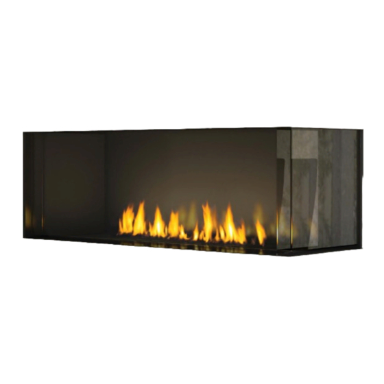
Zero Clearance Direct Flue Gas Fireplace
STYLE
Left Corner
Right Corner
Warning
Fire or explosion Hazard
failure to follow safety warnings exactly could result in serious
injury, death, or property damage.
- Do not store or use gasoline or other flammable vapors and liquids in the vicinity of this or any other
appliance.
- WHAT TO DO IF YOU SMELL GAS
•
Do not try to light any appliance.
• Do not touch any electrical switch: do not use any phone in your building.
Leave the building immediately.
• Immediately call your gas supplier from a neighbour's phone. Follow the gas supplier's
instructions.
• If you cannot reach your gas supplier, call the fire department.
- Installation and service must be performed by a qualified installer, service agency or the gas supplier.
Installer: Please complete the details on the back cover and leave this manual with the homeowner.
920-124b
City Series
MODEL
ACC40LENG / ACC40LELP / ACC40LEULPG
ACC40RENG / ACC40RELP / ACC40REULPG
Homeowner: Please keep these instructions for future reference.
®
Owners &
Installation Manual
LISTINGS AND CODE APPROVALS
These gas appliances have been
tested in accordance with AS/NZS
5263.0 & AS/NZS 5263.1.8:2016
and have been certified by IAPMO
for installation and operation as
described in these Installation and
Operating Instructions.
Must be installed as per AS/NZS5601.
Your unit should be serviced
annually by an authorised service
person.
www.regency-fire.com.au
PRIMARILY A DECORATIVE AND NOT A
HEATING APPLIANCE.
DO NOT MODIFY THIS APPLIANCE.
10.01.20
Advertisement
Table of Contents

Related Manuals for Regency Fireplace Products ACC40E City Series


Summary of Contents for Regency Fireplace Products ACC40E City Series
- Page 1 City Series ® Owners & Zero Clearance Direct Flue Gas Fireplace Installation Manual LISTINGS AND CODE APPROVALS These gas appliances have been tested in accordance with AS/NZS 5263.0 & AS/NZS 5263.1.8:2016 and have been certified by IAPMO for installation and operation as described in these Installation and Operating Instructions.
- Page 2 To the New Owner: Congratulations! You are the owner of a state-of-the-art Gas Fireplace by REGENCY . The City Series are hand crafted appliances and have ® been designed to provide you with all the warmth and charm of a wood fireplace at the flick of a switch. The ACC40LE / ACC40RE City Series have been approved by IAPMO for both safety and efficiency.
-
Page 3: Table Of Contents
table of contents Owner's Information Dura-vent Vertical Termination ........49 Vertical Termination 102mm x 175mm Flueing Copy of Data Badge ............4 - Vertical Flex Flue Kit ..........50 Dimensions (Left Corner) ..........5 Vertical Flue Extension Kit ...........52 Dimensions (Right Corner) ..........6 Ceiling Firestop / Firestop Spacer .......52 Important Message ............7 System Data ..............53 Before You Start .............7... -
Page 4: Copy Of Data Badge
data badge This is a copy of the label that accompanies Direct Flue Gas Fireplace. We have printed a copy of the contents here for your review. The safety label is located on the front inside base of the unit, visible when the outer front panel is removed. NOTE: Regency ®... -
Page 5: Dimensions (Left Corner)
dimensions Dimensions (Left Corner) 1203mm 616mm 587mm 102mm 172mm 1219mm 475mm 449mm 1109mm 1089mm 375mm Note: Height dimension may vary depending on the height of the leveling legs. Note: These units are non-load bearing. ALL PICTURES / DIAGRAMS SHOWN THROUGHOUT THIS MANUAL ARE FOR ILLUSTRATION PURPOSES ONLY. ACTUAL PRODUCT MAY VARY DUE TO PRODUCT ENHANCEMENTS. -
Page 6: Dimensions (Right Corner)
dimensions Dimensions (Right Corner) 1203mm 587mm 616mm 102mm 172mm 475mm 448mm 1108mm 374mm 1091mm Note: Height Dimension may vary depending on the height of the leveling legs. Note: These units are non-load bearing. | City Series ACC40E... -
Page 7: Important Message
owner's information Important Message WE RECOMMEND REMOVING THE CHILDREN AND ADULTS SHOULD BE SAVE THESE INSTRUCTIONS GLASS WITH THE GLASS VACUUM ALERTED TO THE HAZARDS OF HIGH HOLDERS SUPPLIED BY THE MANU- SURFACE TEMPERATURES, ESPE- City Series Direct Flue Fireplaces must be FACTURER. -
Page 8: General Safety Information
owner's information General Safety Information 1. The appliance installation must conform with local codes or, in the absence of local codes, with the current Installation and Building Codes. 2. The appliance when installed, must be electri- cally grounded in accordance with local codes. 3. -
Page 9: Lighting Procedure
owner's information Lighting Procedure IMPORTANT: The remote control system supplied with this appliance has Note: The first try for ignition will last approximately 60 seconds. If there is no several options for starting/operating the appliance using the battery holder flame ignition (rectification) the board will stop sparking for approximately and ON/OFF key on the hand held transmitter. -
Page 10: Copy Of The Lighting Plate Instructions
owner's information Copy of the Lighting Plate Instructions FOR YOUR SAFETY READ BEFORE LIGHTING SUITABLE ONLY FOR INDOOR INSTALLATION This appliance must be installed in accordance with local codes, if any. If none, follow the current AS/INZS 5601. WARNING: If you do not follow these instructions exactly, a fire or explosion may result causing property damage, personal injury or loss of life. -
Page 11: Proflame Ii Remote Control Operating Instructions
owner's information Proflame II Remote Control Operating Instructions IMPORTANT:The Proflame Transmitter 2 is an integrated part of the TECHNICAL DATA Proflame 2 System, which consists of these elements: REMOTE CONTROL • Proflame 2 Transmitter, to be used in conjunction with: •... - Page 12 owner's information Temperature Indication Display Remote Flame Control With the system in the "OFF" position, press the Thermostat Key and the The Proflame has six (6) flame levels. With the system on, and the flame Mode Key at the same time. Look at the LCD screen on the transmitter to level at the maximum in the appliance, pressing the Down Arrow Key verify that a C or F is visible to the right of the room temperature display once will reduce the flame height by one step until the flame is turned off.
- Page 13 owner's information Remote Dimmer Control (Light)** Smart Thermostat (Transmitter Operation) The auxiliary function controls the AUX power outlet by the dimmable The Smart Thermostat function adjusts the flame height in accordance to the light control. To activate this function use the Mode Key (fig. 1) to index difference between the set point temperature and the actual room temperatures.
- Page 14 owner's information Continuous Pilot/Intermittent Pilot (CPI/IPI) Selection 5. "Clr" will remove a mode—use the up or down arrow while holding down ON/OFF and MODE (mode icon will disappear once removed). Note: Power vent models do not have a Continuous 6. Use the "MODE" button to move to the next function. Pilot option.
-
Page 15: Inner Glass Panel Installation / Removal
owner's information Inner Glass Panel (Firebox Glass) Installation / Removal To watch the firebox installation video click here http://bit.ly/2qfQwST Note: glass panels must be installed to operate fireplace Push side glass WARNING: GLASS HANDLING panel firmly to back wall We recommend using the glass vacuum holders supplied by the manufac- until springs are turer. - Page 16 owner's information 5. Ensure all 7 front clamps are in the open position to allow clearance for Note: Ensure that the front glass is centered and evenly spaced with side glass tooltip the glass. (3 sided unit) - open to release glass clamps to remove from surface of glass. Open clamps prior to plac- ing front glass...
-
Page 17: Outer Safety Glass Panel Installation / Removal
owner's information Outer Safety Glass Panel (Barrier Glass) Installation / Removal To watch the safety barrier glass installation video click here http://bit.ly/2ryq0c0 Note: safety glass panels must be installed to operate fireplace 3. Tilt the top of the glass panel inward and lift up and underneath the upper front panel of the outside frame. - Page 18 owner's information Outer Safety Glass Panel (Barrier Glass) Installation / Removal Note: safety glass panels must be installed to operate fireplace. Note: After the side panel has been adjusted so it is installed at 90º to the 4. For 3 sided and corner units only: unit and not flaring in or out, check to ensure there is no gap between With front panel installed, proceed to install the side panel(s).
-
Page 19: Maintenance Instructions
owner's information Maintenance Instructions Glass Replacement elbows, and exterior portions of the system being exposed to cold weather. In the event that you break your glass by impact, 1. Always turn off the gas valve before cleaning. 4. Inspect joints, to verify that no pipe sections or purchase your replacement from an authorized For relighting, refer to lighting instructions. -
Page 20: Installer's Information
installer's information Locating Your Gas Fireplace Unit Assembly Prior to Installation Before you start 1. When selecting a location for your fireplace, ensure that the clearances are met. The ACC40LE/ACC40RE has 4 standoffs, 2 on one side and 2 at the back that need assembly 2. -
Page 21: Installation Checklist
installer's information Installation Checklist 2. If required, adjusting the primary air to ensure that the flame does not carbon. First allow the 1. Locate appliance. Refer to the following sections: unit to burn for 15-20 min. to stabilize. a) Locating Your Fireplace b) Clearances CAUTION: Any alteration to the product that causes c) Combustible Mantel Clearances... -
Page 22: Nailing Strips
tooltip installation Nailing Strips Nailing strips are shipped folded flat against the unit. Fold nailing strips out 90º before installing unit. Secure nailing strips to framing using wood or metal screws. Side nailing strip CC40RE tooltip Side nailing strip CC40LE Top nailing strip Top Nailing Strip Nailing strip is shipped with the appliance and will... - Page 23 installation Clearances The clearances listed below are minimum distances unless otherwise stated: A major cause of chimney related fires is failure to maintain required clearances (air space) to combustible materials. It is of the greatest importance that this fireplace and flue system be installed only in accordance with these instructions. Note: ACC40LE shown in illustration.
-
Page 24: Clearances
installation Clearances Lo w framing with vents Low framing with vents in front/sides or top ACC40LE shown Floor to ceiling with top op Floor to ceiling with top opening ACC40LE shown | City Series ACC40E... - Page 25 installation Clearances Chase enclosed Full framing with low vents in front or sides ACC40LE shown ACC40LE shown Full framing with vents in front or sides City Series ACC40E |...
-
Page 26: Mantel Clearances
installation Mantel Clearances Combustible mantel clearances from top of front facing are shown in the diagram on the right. 13mm Plasterboard, timber, timber panel, etc. 305mm 229mm 130mm Top of Bottomof Fireplace Fireplace Opening Opening 383mm | City Series ACC40E... -
Page 27: Framing Dimensions (Left Corner)
installation Framing Dimensions (Left Corner) NOTE: Framing may be constructed of combustible material (ie. 51mm x 102mm) and does not require steel studs. Note: A combined minimum of Framing 774 square centimetres of open Description ACC40LE Dimensions area is required for the convection air outlet to cool the enclosure. -
Page 28: Framing Dimensions (Right Corner)
installation Framing Dimensions (Right Corner) NOTE: Framing may be constructed of combustible material (ie. 51mm x 102mm)and does not require steel studs. Note: A combined minimum of Framing Description ACC40RE 774 square centimetres of open Dimensions area is required for the convection Framing Height 949mm air outlet to cool the enclosure. -
Page 29: Wall Board/Plasterboard Installation
installation Wall Board/Plasterboard Installation WARNING! Risk of Fire! Comply with all minimum clearances to combustibles as specified. Finishing Instructions It is important to follow the framing and finishing instructions to ensure proper placement of fireplace into the surrounding framing/finishing materials. Wall board materials 13mm thick are specified in this installation manual to properly align with the optional finishing methods offered with this appliance. -
Page 30: Framing And Finishing Inset Installations
installation Framing and Finishing Inset Installations 1. Frame in the enclosure for the unit with framing material Note: When constructing the framed opening ensure there is sufficient access to install the gas lines,electrical. Also the wiring harness must be wall mounted using the receptacle provided with the appliance. The wiring harness will be located on the right hand side of the appliance if facing the unit from the front. -
Page 31: Optional Framing Kit Installation
CITY SERIES installation Optional Framing Kit Installation CC40LE/CC40RE FRAMING KIT INSTALLATION To watch the framing kit installation video click here http://bit.ly/2qvHIsE This framing kit is for the CC40LE/CC40RE. The parts are adaptable so 1. This framing kit requires the installation of two studs at locations shown the same kit can be installed on either the right or left side units. - Page 32 CITY SERIES installation 3. Install B to the side of the unit, use the holes corresponding with the 5. Slide unit against wall and line up part C's with studs in the wall. appropriate shape (diamond or square depending on which unit you Attach both part C's to studs with at least two screws each;...
- Page 33 CITY SERIES installation 12. Identify J (diagonal support) and attach to back corners C and front 9. Identify F and attach to both E and D with 2 screws on each side. corner F with 2 screws on each side. 10.
-
Page 34: Building Additional Framing Off Of The Framing Kit
CITY SERIES installation BUILDING FRAMING OFF OF THE KIT Building Additional Framing Off of the Framing Kit Potential Wood Framing installs This framing kit is designed as a base in which to build additional framing. Studs can be affi xed to all outer faces using the holes identifi... -
Page 35: Tv Recessed Into Wall- Typical Installs
installation TV Recessed Into Wall - Typical Installs Maximum TV Recess TV Flush with Hearth City Series ACC40E |... -
Page 36: Exterior Flue Termination Locations
installation Exterior Flue Termination Locations FIGURE 6.2 (in part): LOCATION OF FLUE TERMINALS OF BALANCED FLUE AS/NZ 5601, ROOM-SEALED, FAN ASSISTED OR OUTDOOR APPLIANCE | City Series ACC40E... - Page 37 installation Minimum clearances (mm) Ref. Item Natural Draught Assisted Below eaves, balconies and other projections: Appliances up to 50 MJ/h input Appliances up to 50 MJ/h input From the ground, above a balcony or other surface* From a return wall or external corner* From a gas meter (M) (see Note 5) (see Clause 5.11, 5.9 for vent terminal location of regulator) 1000...
-
Page 38: Wall Mount On / Off Switch And Installation
installation Wall Mount On / Off Switch and Battery Holder Installation Required for all installations IMPORTANT INSTALLATION NOTE: The Battery Holder must be placed inside the supplied (Low Voltage) junction type wall box and installed into the wall only. DO NOT INSTALL WITHIN THE CONFINES OF THE FIREPLACE SWITCH MUST BE ACCESSIBLE Battery Holder Installation 1. -
Page 39: Flue Restrictor Position
installation Flue Restrictor Position Flue restriction is required for certain venting installations, see the diagrams in the "Venting Arrangements" section to determine if they are required for your installation. The Flue Restrictor plate is packed in the instruction manual package. To set the flue restriction as indicated in the venting arrangements diagrams, refer to the following instructions;... -
Page 40: Horizontal Terminations
installation Horizontal Terminations Flex Flue 102mm x 175mm These venting systems, in combination with the ACC40LE/ACC40RE Direct Flue Gas Fireplace, have been tested and listed as a direct flue heater system by Warnock Hersey/ Intertek. The location of the termination cap must conform to the requirements in the Flue Terminal Locations diagram in "Exterior Flue Termination Locations"... -
Page 41: Venting Introduction
installation Venting Introduction The ACC40LE/ACC40RE uses the "balanced flue" technology Co-Axial system. The inner liner vents products of combustion to the outside while the outer liner draws outside combustion air into the combustion chamber thereby eliminating the need to use heated room air for combustion and losing warm room air up the chimney. -
Page 42: Horizontal Terminations
installation Horizontal Terminations Rigid Pipe 102mm x 175mm The minimum components required for a basic horizontal termination are: Horizontal Termination Cap Rigid Pipe Adaptor (510-994) Wall Thimble Length of pipe to suit wall thickness (see chart) Wall thickness is measured from the back standoffs to the inside mounting surface of termination cap. - Page 43 installation Horizontal Terminations Rigid Pipe 102mm x 175mm The diagrams below show examples of horizontal termination arrangements using one, two, or three 90 elbows (two 45 elbows equal one 90 elbow) 1. A maximum of three 90 elbows are permitted. 2.
-
Page 44: Vertical Terminations
installation Vertical Terminations Rigid Pipe 102mm x 175mm The minimum components required for a basic vertical termination are: Vertical Termination Cap Rigid Pipe Adaptor (510-994) Ceiling Firestop Flashing Storm Collar Length of pipe to suit wall thickness (see chart) Galvanized pipe is desirable above the roofline due to its higher corrosion resistance. -
Page 45: Flueing Arrangement For Vertical Terminations
installation Flueing Arrangement for Vertical Terminations Vertical Flueing with Straight Vertical Flueing and or with a max. of two (2) 90 Elbows (1 - 90 2 - 45 The shaded area in the diagram shows all allowable combinations of straight vertical and offset to vertical terminations, using two elbows, with Rigid Pipe Flueing Systems. -
Page 46: Vertical Terminations
installation Vertical Terminations Rigid Pipe 102mm x 175mm • Two 45 elbows equal to one 90 elbow. Maximum of six 45 elbows allowed. • Flue must be supported at offsets. • Minimum distance between elbows is 305mm. • Maintain clearances to combustibles as listed in the "Clearances" section. •... -
Page 47: Unit Installation With Horizontal Termination
installation Unit Installation with Horizontal 5. Assemble the desired combination of pipe and 7. Ensure that the pipe clearances to combustible elbows to the appliance adaptor and twist-lock materials are maintained (Diagram 3). Install Termination for a solid connection. the termination cap. 102mm x 175mm Flueing (Rigid Flue Systems) - Page 48 installation Unit Installation with Horizontal NOTE: Horizontal sections must be sup- ASTROCAP ported at intervals not exceeding Termination DIMENSIONS (946-523/P) 0.9 meter. (Flame picture and per- 102mm x 175mm Flueing formance will be affected by sags (Flex Flue Systems) in the liner). Minimum Flue Clearances 4.
-
Page 49: Dura-Vent Vertical Termination
installation Dura-vent Vertical Termination 5. Cut an opening in the roof centered on the small drilled hole placed in the roof in Step 2. 102mm x 175mm Flueing The hole should be of sufficient size to meet (Rigid Flue Systems) the minimum requirements for clearance to combustibles of 38mm. -
Page 50: Vertical Termination 102Mm X 175Mm Flueing - Vertical Flex Flue Kit
installation VERTICAL TERMINATION Vertical Termination 102mm x 175mm Flueing - Vertical Flex Flue Kit (946-755) 102MM X 175MM FLUEING - VERTICAL FLEX VENT KIT (946-755) Note: The roof fl ashing is not included with this kit and must be purchased separately. - Page 51 installation 13. Slide the fi nished length up towards the fl ashing ensuring the length of pipe is a minimum of 0.6m measured from the top of the roof. Level the chimney and secure using the roof support provided with kit to bottom side of the roof as shown using a minimum of 2 screws per side- see Diagram 3b.
-
Page 52: Vertical Flue Extension Kit
installation VERTICAL FLUE EXTENSION KIT (APPROVED MODELS) Vertical Flue Extension Kit (Part #946-756) (PART # 946-756) 6.1m Flex pipe Extension CEILING FIRESTOP/FIRESTOP SPACER 100mm inner pipe 6.1m Used in conjunction with the 946-755 Vertical Flex kit for vertical installations ( PART # 946-757) or for horizontal installations when using the power vent option only where a maximum of 2 x 946-756 may be used up to a maximum of 12.2m. -
Page 53: System Data
installation Pilot Adjustment 885 S.I.T. Valve Description ACC40ENG SYSTEM DATA Min. Supply Pressure 1.13 kPa 1) 6 Stage flame adjustment Periodically check the pilot flames. Correct flame 2) Pilot adjustment pattern has two strong blue flames: 1 flowing Manifold Pressure High 0.96 kPa 3) Outlet Pressure Tap around the flame sensor and 1 flowing across... -
Page 54: Wiring Diagrams
installation Wiring Diagrams (Do not cut the earth terminal off under any Caution: Ensure that the wires do not No electrical power supply is required for the gas control to operate. 240 Volt AC power is needed circumstances.) touch any hot surfaces and are away from for the lights. -
Page 55: Optional Fan Ducting Kit Installation
installation City Series 40 ACB40E Optional Fan Ducting Kit Installation OPTIONAL FAN DUCTING KIT INSTALLATION Note: The 656-995 HeatWave adapter and 946-596 Aluminum flex (4.5m) must be purchased separately. LISTINGS AND CODE GENERAL INFORMATION Maximum Duct Run: 9.0m APPROVALS Kit Contains 4.5m The Fan Kit increases the effectiveness of your fireplace by dispersing warm air from the fireplace If you require more than 4.5m please purchase Fan... - Page 56 installation City Series 40 ACB40E OPTIONAL FAN KIT INSTALLATION NOTE: Installation of Fan Kit should be done prior to 9. Attach oval to round collar/base adapter as- Air Duct installation of the wall. sembly (assembled in step 8) to unit in location shown below with 4 screws.
-
Page 57: Fan Duct Extension Kit
City Series 40 ACB40E installation OPTIONAL FAN KIT INSTALLATION Fan Duct Extension Kit FAN DUCT EXTENSION KIT In order to use the fan extension duct kit, you must have fan kit. This kit allows you to extend the fan duct to 9m. 2. -
Page 58: Inner Glass Panel I(Firebox Glass) Installation / Removal
installation Inner Glass Panel (Firebox Glass) Installation / Removal To watch the firebox installation video click here http://bit.ly/2qfQwST Note: glass panels must be installed to operate fireplace Push side glass WARNING: GLASS HANDLING panel firmly to back wall We recommend using the glass vacuum holders supplied by the manufac- until springs are turer. - Page 59 installation Note: Ensure that the front glass is centered and evenly spaced with side glass 5. Ensure all 7 front clamps are in the open position to allow clearance for tooltip (3 sided unit) - open to release glass clamps to remove from surface of glass. the glass.
-
Page 60: Outer Safety Glass Panel (Barrier Glass) Installation / Removal
installation Outer Safety Glass Panel (Barrier Glass) Installation / Removal To watch the safety barrier glass installation video click here http://bit.ly/2ryq0c0 Note: safety glass panels must be installed to operate fireplace 3. Tilt the top of the glass panel inward and lift up and underneath the upper front panel of the outside frame. - Page 61 installation Outer Safety Glass Panel (Barrier Glass) Installation / Removal Note: safety glass panels must be installed to operate fireplace. Note: After the side panel has been adjusted so it is installed at 90º to the 4. For 3 sided and corner units only: unit and not flaring in or out, check to ensure there is no gap between With front panel installed, proceed to install the side panel(s).
-
Page 62: Propane/Ulpg Conversion Instructions
installation CITY SERIES Propane/ULPG Conversion Instructions CONVERSION FROM NG TO LP/ULPG Using SIT 885 NOVA Gas Valve THIS CONVERSION MUST BE DONE BY A QUALIFIED GAS FITTER IF IN DOUBT DO NOT DO THIS CONVERSION! WARNING 6. If unable to access this Cable - undo 2 screws securing the IFC Board and slide out of unit to access cable. - Page 63 CITY SERIES installation 11. Loosen 4 screws in locations shown below (2 at front and 2 at rear)—slide burner to the left away from the orifice and lift out. front screw locations 14. Unscrew the pilot orifice with the allen key; then replace with the LPG pilot orifice and the pilot cap, provided in the kit.
-
Page 64: Painted Panel Installation
installation CITY SERIES Painted Panel Installation Inner Panels CC40RE/CC40LE INNER PANELS The CC40RE/CC40LE can be equipped with optional steel inner panels. 5. Manoeuvre in side panel to the side wall of the unit—secure in place There are 4 outer panels and 3 inner panels. with 1 panel clips and 1 screws. -
Page 65: Enamel Panel Installation
CITY LINE maintenance CC40RE/CC40LE ENAMEL PANEL INSTALLATION Enamel Panel Installation Black Enamel Panels — Handling Instructions • Black Enamel panels must be inspected for scratches and dimples prior to installation. All claims to be recorded at this time. Claims for damage after installation will not receive consideration. •... - Page 66 CITY LINE maintenance CC40RE/CC40LE OUTER PANELS Note: Install inner safety glass prior to installation of outer panels-see instructions in manual 1. Attach Regency logo to the right hand side of outer front panel. The magnets will be positioned under the outer front base panel to secure the logo.
-
Page 67: Burner And Firebox Media Options
installation Burner and Firebox Media Options Spread the media evenly over the burner. Ensure the glass/stones do not overlap excessively as this will affect the flame pattern. IMPORTANT NOTE: Only the supplied approved media are to be used with these fireplaces. Use of any other type of glass or stones can alter the unit's performance. Any damage caused by the use of any unapproved glass or stones will not be covered under warranty. -
Page 68: Optional Driftwood Log Set Installation
installation CITY LINE Optional Driftwood Log Set Installation CITY LINE - LOG INSTALLATION Read the instructions below carefully and refer to the images. If the logs are broken do not use the unit until they are replaced. Broken logs can interfere with pilot operation. Improper positioning of the logs may create carbon build-up and can alter the unit's performance which is not covered under warranty. - Page 69 CITY LINE installation 8. Place the split end of Log 3 to the right front corner of the burner—angle Rest the other end of Log 4 on the indent in Log 2 as shown below. the log so that the other end is sitting approximately 13mm from the edge of the burner tray.
-
Page 70: Removable Plasterboard Guides
installation Removable Plasterboard Guides (when using 13 mm plasterboard) An optional finishing trim is available to finish the edges of the installation on 5. Reverse steps to reinstall plasterboard guides (if applicable). If discarding, the ACC40RE/ACC40LE unit. Installation is as follows: please recycle. -
Page 71: First Fire
operating instructions Aeration Adjustment First Fire Normal Operating Sounds of Gas Appliances The burner aeration is factory set but may need The FIRST FIRE in your fireplace is part of the adjusting due to either the local gas supply or paint curing process. -
Page 72: Maintenance
maintenance Bulb Replacement 1. Turn off unit and allow to cool to room temperature. 4. Loosen 2 screws on each side of individual inner light cover and remove. 2. Remove outer safety glass panels and inner panels (firebox glass)–see 5. Remove glass cover by using a flat head screwdriver to pry the tab securing instructions in this manual. -
Page 73: Valve Replacement
maintenance Valve Replacement Important: Always shut off gas supply/240 volt power prior to servicing the 7. Lift valve tray by out partially and disconnect flexible gas connection on the gas valve. valve inlet side, remove valve tray- replace with new valve tray. tooltip 1. -
Page 74: Gas Appliance Maintenance
Gas Maintenance maintenance Gas Appliance Maintenance Recommended Annual Routine Maintenance for Gas Fireplaces, Stoves and Inserts In order for your Regency appliance to continue to provide comfort to your home periodic maintenance must be performed to ensure it is operating at peak efficiency. The items in the list should be checked by a licensed gas service technician during the annual service check. Your unit may require more frequent maintenance checks if you notice any changes in how it operates. Operational changes to look for can include, but are not limited to, extended start up time, increased fan noise, residue/carbon build up, white build up on the glass/firebox, increased operating noise etc. Should any of these or other conditions arise, discontinue use and schedule a service check with your local licensed gas technician. The list below shows items your licensed service technician will need to check and service at least annually. Clean Inspect Check • Glass • Pilot assembly • Voltage on thermocouple/thermopile (mil- • Interior bricks / panels • Burner livolt models) • Burner ports & burner air shutter • Pressure relief gaskets/doors •... -
Page 75: Main Assembly
parts list Main Assembly 910-576 Cover Wall Mount White GTM SIT 0.584.803 905-039 Burner Orifice #54 ULPG 911-173 Wire Harness IFC No CPI Switch 584.924 657-525 Burner Assembly - NG/LP 911-177 Wire 4 Position IFC Fan & Light 656-046 Pilot Cover/Shield 911-181 Wire Harness Battery Box Proflame II 911-006... - Page 76 parts list 946-591 Heatwave Fan Kit 946-675 Fireglass Black Reflective 6mm /454g Pkg 946-676 Fireglass Copper 6mm /454g Pkg 946-677 Fireglass Starfire 6mm /454g Pkg 946-596 Heatwave Duct Kit 946-780 Crushed Glass Coal Black 19mm / 1.6kg 946-739 Firebeads Black 2.3kg Pkg 946-710 Stones -Slate/Grey Basalt Natural 6.8kg 946-711...
- Page 77 parts list Main Assembly 905-039 Burner Orifice #54 ULPG 910-576 Cover Wall Mount White GTM SIT 0.584.803 657-525 Burner Assembly - NG/LP 911-173 Wire Harness IFC No CPI Switch 584.924 656-046 Pilot Cover/Shield 911-177 Wire 4 Position IFC Fan & Light 911-276 Pilot Assembly IPI NG 2 Flame 911-181...
- Page 78 parts list 657-968 Conversion Kit - Propane ULPG 656-991 Chase Flue Front Black 656-995 Adaptor Heat Wave 656-953 Chase Steel Framing Kit 657-991 Chase FLue Flush Front White 946-591 Heatwave Fan Kit 946-675 Fireglass Black Reflective 6.35 mm 454g Pkg 946-676 Fireglass Copper 6 mm / 454g Pkg 946-677...
- Page 79 notes City Series ACC40E |...
-
Page 80: Warranty
warranty Limited Lifetime Warranty FPI Fireplace Products International Ltd. (“the manufacturer”) through its wholly owned subsidiary, Fireplace Products Australia Pty Ltd (for Australia and New Zealand customers) and sold under the Regency® brand of fireplace products (collectively referred to herein as “FPI”), extends this Limited Lifetime Warranty to the original purchaser of this appliance provided the product remains in the original place of installation. - Page 81 warranty part is returned to the distributor, dealer or agent for inspection if requested by FPI. Alternatively, FPI may at its own discretion fully discharge all of its obligations under the warranty by refunding the verified purchase price of the product to the original purchaser. The purchase price must be confirmed by an original copy of the tax invoice. The authorised selling dealer, or an alternative authorised FPI dealer if pre-approved by FPI, is responsible for all in-field diagnosis and service work related to all warranty claims.
- Page 82 warranty FPI has no obligation to enhance or modify any unit once manufactured (i.e. as products evolve, field modifications or upgrades will not be performed on existing appliances). Any unit showing signs of neglect or misuse will not be covered under the terms of this warranty policy and may void this warranty.
- Page 83 warranty Limitations of Liability: 1. Exclusion of implied terms The customer may have the benefit of consumer guarantees under the Australian Consumer Law. To the maximum extent permitted by law, all terms, conditions or warranties that would be implied into this Warranty or in connection with the supply of any goods or services by the supplier under law or statute or custom or international conventions are excluded.
- Page 84 Product Registration and Customer Support: Thank you for choosing a Regency Fireplace. Regency strives to be a world leader in the design, manufacture, and marketing of hearth products. To provide the best support for your product, we request that you complete a product registration form found on our Web Site under Customer Care within ninety (90) days of purchase.
- Page 85 notes City Series ACC40E |...
- Page 86 | City Series ACC40E...
- Page 87 notes City Series ACC40E |...
- Page 88 Installer: Please complete the following information Dealer Name & Address: _______________________________________________ ___________________________________________________________________ Installer: ____________________________________________________________ Phone #: ___________________________________________________________ Date Installed: _______________________________________________________ Serial #: ____________________________________________________________ © Copyright 2020, FPI Fireplace Products International Ltd. All rights reserved.
Need help?
Do you have a question about the ACC40E City Series and is the answer not in the manual?
Questions and answers