Table of Contents
Advertisement
Quick Links
Advertisement
Table of Contents

Subscribe to Our Youtube Channel
Related Manuals for Etatron eOneMa


Summary of Contents for Etatron eOneMa
-
Page 2: Table Of Contents
CONTENTS SAFETY ....................................3 Wa rn ing s ............................... 3 Sym b ols used in th is m a n u al ......................... 3 Dang ero us and /o r to xi c l iq u id d o sag e ....................3 GENERAL REGULATION .............................. -
Page 3: Safety
SAFETY Warni ngs Carefully read the warnings listed below as they contain important information regarding safety during installation, use and maintenance. Keep this manual in a safe place for further consultation. This equipment complies with the 2004/108/EEC directive regarding “electromagnetic compatibility” with the 2006/95/CEE “low voltage directive”. -
Page 4: Proper Use Of The Pump
Proper use of the pump The pump must only be used for the purpose which it was expressively manufactured, i.e to dose liquids. Any other use is considered improper and therefore dangerous. The pump is not foreseen for use in any applications not taken into consideration during the design stage. -
Page 5: Risks
Risks After removing the packaging, check the pump for any damage. If in doubt do not use the pump and contact qualified personnel. All packaging elements (such as plastic bags, polystyrene, etc.) must be kept out of the reach of children as the material is potentially dangerous. -
Page 6: Analogic Dosing Pumps Eone Ma Series
ANALOGIC DOSING PUMPS EONE MA SERIES Operating princip les Dosing pump operation is ensured by a PTFE (teflon®) membrane mounted on the piston of an electromagnet. When the piston of the electromagnet is attracted, pressure is produced in the pump head and liquid is ejected from the discharge valve. Once the electrical impulse has terminated a spring brings the piston back to its original position and liquid is called in through the suction valve. -
Page 7: Overall Dimensions
The values listed above are intended to be within a tolerance of +/- 5%. They were obtained by a series of test performed on similar equipments with water at temperature of 20°C. Overall dimensions Fig. 1 - Dimensions in mm. Plate for wall mounting. Material in contact with the additive In the standard configuration the pumps of the "eOne"... -
Page 8: Installation
INSTALLATION Introduction This section describes steps for installing the pump, hoses and wiring. Please read this instruction before starting any activity. Follow these guidelines when installing the pump: Make sure the pump is powered off and any other related equipment before starting any activity. ... -
Page 9: Tubes Connection
Fig.3 – Electrical scheme Tubes connection The discharge nipple will always be at the top side of the pump from where the tube goes to the plant to be treated. The suction nipple will always be at the bottom side of the pump, where the tube will be mounted with the filter that goes to the tank of the liquid to be dosed. -
Page 10: Typical Installation
Fig.5 – Priming sequence Typical installation Main pipeline Injection valve Backpressure valve Pressure gauge Relief valve Power supply plug Chemical tank Foot filter Level probe... -
Page 11: Accessories
Fig. 6 – Typical installation Avoid unnecessary curves and narrow on both the discharge and suction pipes. Apply a 3/8 " or ½" BSP female nipple on the conduct of the plant to be treated, in the most suitable location for the injection of the product to be dosed. This nipple is not supplied. -
Page 12: Commands Description
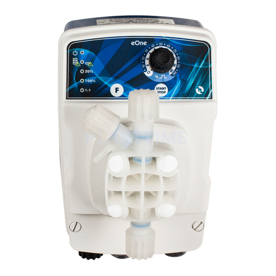
Fig.8 - Commands panel Adjustment knob frequency (%) of the number of injections START/STOP button Button function selection: full scale 20/100% / entrance 1:1; activation and deactivation function UNDER- LOAD / OVER-LOAD held down for 5 sec. 1:1 function display external signal “green” LED 100% flow scale read out “green”... -
Page 13: Level Alarm And 1:1 Signal Input
same LED with green color (7) indicates that the function has been disabled. During this steps the pump stop dosing and start after the function has been enbled/disabled.OVERLOAD and UNDERLOAD functions are disable by factory default. Level alarm and 1:1 signal input The pump is supplied with a connector for a level switch (supplied on request). -
Page 14: Ordinary Maintenance
ORDINARY MAINTENANCE An Ordinary and accurate maintenance with a programmed check, guarantee the preservation over time and the proper functioning of the systems. Therefore we recommend that the user follow our advice and maintenance of a service contract and assistance programmed with one of our Technical Support Center. Check at least every 6 months functioning of the pump. -
Page 15: Appendix 1 - Pump Drawings
APPENDIX 1 – PUMP DRAWINGS 1. pump head screws to tighten the four screws use a dynamometer screwdriver set to a tightening torque of 180÷200 Nxcm using a hexagonal insert of 2,5 mm 1 -ELECTROMAGNET 2 –PUMP HEAD 3 –PC BOARD... -
Page 16: Appendix 2 - Exploded Views
SCHEDA MORSETTI APPENDIX 2 – EXPLODED VIEWS 1. Plastic casing 2. Plastic cover 3. Pump head 4. Electromagnet 5. Pump gasket 6. PC-board 7. Knob basket 8. Adjustment knob 9. Flange 10. Diaphragm 11. Pump head basket 12. power cord... - Page 17 1. Ring nut 2. Bush 3. Nozze 4. O-ring 106 5. Body filter 6. Ceramic ball 7. O-ring 3030 8. O-ring 3081 9. Valve seat 10. Filterinig basket 1. Ring nut 2. Bush 3. Nozze 4. O-ring 106 5. Injection valve nipple 6.
Need help?
Do you have a question about the eOneMa and is the answer not in the manual?
Questions and answers