Table of Contents
Advertisement
Quick Links
Advertisement
Table of Contents

Related Manuals for Etatron BT Series


Summary of Contents for Etatron BT Series
- Page 3 - web: www.etatronds.com ITALY (BRANCH OFFICE) ASIA BRASIL ETATRON D.S. ETATRON D.S. ETATRON do Brasil LTDA Via Ghisalba, 13 Rua Vidal de Negreiros, 108 (Asia-Pacific) PTE Ltd 20021 Ospiate di Bollate Bairro Caninde - Sao Paulo S.P. 67 Ubi Crescent, #03-05...
-
Page 4: Table Of Contents
CONTENTS pa 29 1.0 – GENERAL REGULATIONS 1.1 - WARNINGS 1.2 – SHIPPING AND HANDLING 1.3 – PROPER USE OF THE PUMP 1.4 - RISKS 1.5 - DANGEROUS AND/OR TOXIC LIQUID DOSAGE 1.6 - ASSEMBLING AND DISMANTLING THE PUMP 2.0 - SERIES BTB MA/AD ANALOGICAL DOSING PUMPS 2.1 –... - Page 5 SYMBOLS Before a very important notes regarding health protection for the exposed personnel or regarding the machine itself WARNING Before safety information, it highlights an operation not to be performed. FORBIDDEN Before information regarding equipment use. INFORMATION...
-
Page 6: General Regulations
1.0 – GENERAL REGULATIONS 1.1 - WARNINGS Carefully read the warnings listed below as they contain important information regarding safety during installation, use and maintenance. • Keep this manual in a safe place for further consultation. electromagnetic compatibility • This equipment complies with the 89/336/EEC directive regarding “ ”, with the 73/23/EEC “low voltage directive”... -
Page 7: Dangerous And/Or Toxic Liquid Dosage
Before performing any maintenance or cleaning operations on the dosing pump, proceed as follows: 1. Make sure the pump is electrically deactivated (both poles) by disconnecting the conductors from the power supply using the omnipolar switch which must have a minimum distance of 3 mm between its contacts (Fig. -
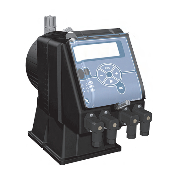
Page 8: Series Btb Ma/Ad Analogical Dosing Pumps
VIEWS AND DIMENSIONS Fig.1) 2.0 – BTB MA/AD SERIES ANALOGICAL DOSING PUMPS 2.1 – OPERATING PRINCIPLES Dosing pump operation is ensured by a PTFE (teflon®) membrane mounted on the piston of an electromagnet. When the piston of the electromagnet is attracted, pressure is produced in the pump body and liquid is ejected from the outlet valve. - Page 9 Fig 2 2/20 5/20 Low and medium ow High ow rates 5/15 rates 1/10 2/10 5/10 10/10 10/7 15/5 20/5 i.v.p. Fig. 3 Fig 2 2/20 5/20 5/15 1/10 2/10 5/10 10/10 10/7 15/5 20/5 i.v.p. Fig. 3 The diagrams (fig. 3) show the variation in maximum flow rate of the dosing pumps when the pressure in the plant being treated changes.
-
Page 10: Installation
3.0 - INSTALLATION a. Install the pump away from heat sources, in a dry place and at a maximum ambient temperature of 40°C. The m i n i m u m o p e r a t i n g t e m p e r a t u r e o f t h e p u m p d e p e n d s o n t h e l i q u i d t o b e d o s e d , a s t h e l i q u i d m u s t r e m a i n i n a f l u i d s t a t e . -
Page 11: Injection Valve Assembly Diagram
Fig. 8 If the pump has to be removed from the plant for any reason whatsoever, it is recommended to reuse the protection capsules to avoid liquid loss from the pump body. f. Priming the pump: if the pump is supplied with a discharge valve, connect the outlet piping and follow the sequence shown in fig.8. -
Page 12: Maintenance
4.0 - MAINTENANCE 1. Periodically check the liquid level in the tank to make sure that the pump does not run dry; even though no damage will occur to the equipment itself, this is recommended to avoid any damages due to the lack of additive in the plant. 2. -
Page 13: Manual Dosing Pump
6.0 – MANUAL DOSING PUMP Manual flow rate adjustment using a potentiometer to intervene on the injection frequency. 6.1 - COMMANDS (Fig. 11) 6.2 – TYPICAL PLANT DIAGRAM 6.3 – ADDITIONAL COMPONENTS SUPPLIED Fig. 12 6.4 – LEVEL ALARM (fig. 13) The dosing pump has a connector to be able to connect a level sensor (optional). -
Page 14: Wiring Diagram And Service Connector Functions
7.0 - SERVICE CONNECTOR WIRING DIAGRAMS AND FUNCTIONS Posizione 1 Posizione 4 Posizione 2 Posizione 3 Fig 13 REALY OUTPUT Normally open (N.O.) Normally closed (N.C.) Common No connection LEVEL PROBE/FLOW SENS. +mA (+) Red wire mA output (-) Black wire mA output Level probe wire/flow sens. -
Page 15: Display Description
8.0 - DISPLAY DESCRIPTION 6.5 - DISPLAY DESCRIPTION Overdosing alarm Delay at powering on Setpoint setting Level alarm Alarms setting Menu selection ON-OFF functioning mode Proportional functioning mode Temperature probe Hysteresis setting Calibration points Calibration menu General instrument settings Switching-on delay settings Level probe/flow sensor input activation Reset activation Intervention selection... -
Page 16: Parameters And Functions Layout
8.1 - PARAMETERS AND FUNCTIONS LAYOUT (Factory default - pH) 6.6 - PARAMETERS AND FUNCTIONS LAYOUT (Factory default - pH) FUNCTIONS DEFAULT Setpoint setting Hysteresis setting Choice of the type of intervention Acid Manual or proportional intervention selection Manual Definition of beginning intervention value "AUTO" Setpoint + 1pH First point of calibration procedure -------... -
Page 17: Programming
9.0 - PROGRAMMING 7.0 - PROGRAMMING Through the front panel it is possible to set and to modify all the working parameters of operating setting of the pump. 9.1 - PUMP SETUP The first operation to do is to select the type of parameter (pH, Redox or free Chlorine) that is intends to measure and to control. - Page 18 To enter in SETUP menu scroll all menus with + and - buttons up to reach the desired menu (on display will show SETUP), press OK to confirm. On display will appear the last setting previously selected; in case of a new product, the pump has by default BASE (simplified menu), to select the type of parameter to control it is necessary to pass in FULL menu (complete menu - expert users).
- Page 19 9.1.3 - Choice of Input Level/Flow After the password has been determined, it is possible to set up the type of sensor that is necessary to install the pump: When a level sensor is needed to be connected, the LEVEL warning will appear, on the other hand when it is necessary to connect a proximity sensor this icon will appear.
- Page 20 9.1.6 - Calibration exit delay Thanks to this function user can select the time the pump will use to quit from calibration phase setting to come back to the main measuring display. Using + and - it' s possible to set the delay time, from 0 second to 99 min 59 sec.
-
Page 21: Measuring Calibration
9.2 - MEASURING CALIBRATION To calibrate the pump integrated controller, user has to adjust two calibration points for any kind of parameter, i.e. pH, Redox or Chlorine. To enter in CALIB. menu, from measuring mode, press OK button then the + button, on display CALIB. -
Page 22: Setpoint Setting
CHLORINE PROCEDURE (ppm Cl): • Put in a short circuit BNC connector (as shown in figure) using a copper wire. • Adjust the value on the display up to reach 0 using + and - buttons. • Press OK to save the data, on display will appear POINT 2 •... - Page 23 The pump automatically will go in Manual/Proportional menu (ON-OFF or PROP.) or in Hysteresis menu, this depends on SETUP setting. If FULL menu has been activated, Hysteresis menu will appear (go to paragraph 9.3.6), otherwise if BASE menu has been activated, Hysteresis menu will be not present and the pump will be driven with hysteresis default values that are: 0,1 pH;...
- Page 24 9.3.5 - Max frequency adjustment If the user has select Proportional mode (PROP.), after pressing OK button, the pump will pass in Max frequency adjustment menu. User has to set at which pH, Redox or Chlorine level the pump has to dose at the maximum speed. The pump self controls its flow rate from this point, up to the setpoint where it stops dosing (please follow next 3 steps).
-
Page 25: Alarms Setting
9.4 - ALARMS SETTING It is possibleto to plan three different types of alarm pump: 1 - MAX: User can set at which maximum value the pump has to go in alarm mode. When the pump will go over this value, on the display, Alarm message will flash, Alarm Led will flash, in BT-BTB pH-RX-Cl/ M also the relay will be activated (relay output not present in version BT-BTB pH-RX-Cl/MB). -
Page 26: Reset Procedure
9.5 - RESET PROCEDURE The pump is equipped with two RESET procedures. It can be used any time the user has to reset some or entire calibration parameters. Following are described all the steps for partial RESET and for total RESET: •... -
Page 27: Troubleshooting For Common Faults
10.0 – TROUBLESHOOTING FOR COMMON FAULTS 10.1 - MECHANICAL FAULTS As the system is quite robust, normally there are no mechanical problems. Occasionally there might be a loss of liquid from the nipple because the tube nut has become loose, or more simply the outlet piping has broken. It is rare to detect losses due to a broken membrane or due to wear on the membrane seal gasket. -
Page 28: Extraordinary Maintenance
12.0 – EXTRAORDINARY MAINTENANCE All components supplied are chosen and tested according to rigid selection principles and therefore guarantee, for a long period of time, the reliability and operation of our equipment. Due to external problems (such as overvoltages, excessive pressure and water-hammers), any bad or improper use or programming errors, may render necessary extraordinary maintenance in addition to the ordinary maintenance already mentioned. - Page 29 Serie BTB Series...
- Page 30 Serie BT Series...
- Page 31 VALVOLE - VALVES Valvole di iniezione complete di raccordo Complete injection valves VALVOLA INIEZIONE STD. fino a 20 l/h VALVOLA INIEZIONE 1/2” 50 l/h VALVOLA INIEZIONE 90° fino a 20 l/h VALVOLA INIEZ. A SFERA fino a 20 l/h STD. INJECTION VALVE up to 20 l/h 1/2”...
- Page 32 Corpo pompa completo: Corpo pompa con P.P. - PVC - Acciaio inox - PTFE spurgo manuale Complete Pump Head: Manual air bleed P.P. - PVC - Stainless Steel - PTFE pump head 1201/1202 1302 2810/2812 8301 1703 2501 1903 2813÷2818 3900÷3907 8301 2810/2812...
- Page 33 Note:...
- Page 34 Note:...
Need help?
Do you have a question about the BT Series and is the answer not in the manual?
Questions and answers