Table of Contents
Advertisement
Quick Links
- 1 Operation
- 2 Installation
- 3 Injection Valve Installation Diagram
- 4 Multifunctions Dosing Pump Dlx Mf/M - Dlxb Mf/M Series
- 5 Wiring Connection and Output Connector Functions
- 6 Description of Operating Mode
- 7 Trouble Shooting Common to Dlx - Dlxb Mf Series
- 8 Restoration of Default Parameters
- Download this manual
Advertisement
Table of Contents

Related Manuals for Etatron DLX-MF/M


Summary of Contents for Etatron DLX-MF/M
- Page 1 POMPE DOSATRICI SERIE DLX-MF/M E DLXB-MF/M NORME DI INSTALLAZIONE, USO E MANUTENZIONE DLX-MF/M AND DLXB-MF/M SERIES METERING PUMPS OPERATING INSTRUCTIONS AND MAINTENANCE UNI EN ISO 9001 - 9190.ETAD...
-
Page 2: Table Of Contents
INDEX 1.0 - HINTS AND WARNING PAG. 28 1.1 - WARNING 1.2 - SHIPPING AND TRANSPORTING THE PUMP 1.3 - PROPER USE OF THE PUMP 1.4 - RISKS 1.5 - TOXIC AND/OR DANGEROUS LIQUID DOSAGE 1.6 - ASSEMBLING AND DISMANTLING THE PUMP 2.0 - DLX MF/M DLXB MF/M MICROCONTROLLER DOSING PUMPS 2.1 - OPERATION 2.2 - COMMON FEATURES... -
Page 3: Warning
1.0 - HINTS AND WARNINGS Please read the warning notices given in this section very carefully, because they provide important information regarding safety in installation, use and maintenance of the pump. • Keep this manual in a safe place, so that it will always be available for further consultation. •... -
Page 4: Toxic And/Or Dangerous Liquid Dosage
1.5 - TOXIC AND/OR DANGEROUS LIQUID DOSAGE To avoid risk from contact with the hazardous liquids or toxic fumes, always adhere to the notes in this instruc- tion manual: • Follow the instructions of the dosing liquid manufacturer. • Check the hydraulic part of the pump and use it only if it is in perfect condition. •... -
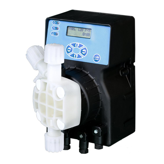
Page 5: Operation
127 mm 192 mm DLX MF/M (wall mounting) DLXB MF/M (basement mounting) 2.0 - DLX-MF/M AND DLXB-MF/M MICROCONTROLLER DOSING PUMPS Multifunctions dosing pumps with a microprocessor and a liquid cristal display allows a accurate injection puls- es choice. 2.1 - OPERATION The metering pump is activated by a teflon diaphragm mounted on a piston of an electromagnet. - Page 6 The pump doses in proportional way to the power signal Operating range: 0 – 20 mA pulses per minute 0-120 pump pulses per minute Minimum and maximum cutoff points are adjustable: Stop/Continue dosing The pump can dose directly in PPM. User can set the following parameters: Water meter liter/contacts 0.1, 0.25, 0.5, 1, 2.5, 5, 10, 25, 50, 100, 250, 500, 1000.
-
Page 7: Liquid Ends Materials
2.3 - LIQUID ENDS MATERIALS - DIAPHRAGM: PTFE - PUMP HEAD: Polypropylene; upon request: PVC, 316 Stainless Steel, PTFE, PVDF. - NIPPLES: polypropylene - FILTER: polypropylene - INJECTION NIPPLE: polypropylene - SUCTION HOSE: PVC - flexible - DISCHARGE HOSE: polyethylene - VALVES: “lip”type FPM (Viton ®... -
Page 8: Installation
3.0 - INSTALLATION a. - Install the pump in a dry place and well away from sources of heat and, in any case, at environmental tem- peratures not exceeding 40°C. The minimum operating temperature depends on the liquid to be pumped, bearing in mind that it must always remain in a liquid state. -
Page 9: Injection Valve Installation Diagram
Fig. 8 Whenever the pump is dismantled from the pipework, you will be well advised to replace the caps on the connectors to avoid residual liquid being spilled. Before attaching the delivery hose to the plant, prime the metering pump by going through the sequence shown in Fig. 8. Before finalizing the installation of the dis- charge hose, make sure that the pump strokes will not cause it to move and bump into rigid bodies. -
Page 10: Maintenance
4.0 - MAINTENANCE 1. Periodically check the chemical tank level to avoid the pump operating without liquid. This would not dam- age the pump, but may damage the process plant due to lack of chemicals. 2. Check the pump operating condition at least every 6 months, pump head position, screws, bolts and seals; check more frequently where aggressive chemicals are pumped, especially: - pulse and power L.E.D.;... -
Page 11: Multifunctions Dosing Pump Dlx Mf/M - Dlxb Mf/M Series
DLX-MF/M • DLXB-MF/M Fig. 11 6.0 - MULTIFUNCTIONS DOSING PUMP DLX MF/M; DLXB MF/M SERIES Multifunctions dosing pump with a microcontroller and a LCD (liquid cristal display) allows an accurate injection pulses choice. 6.1 - PUMP CONTROLS (Fig. 11) 1 - Increasing values button - movement in the programming menu 2 - "Next program"... -
Page 12: Wiring Connection And Output Connector Functions
7.0 - WIRING CONNECTION AND OUTPUT CONNECTOR FUNCTIONS Female service connector wire assembly Functions and technical informations Relay service output connection Configuration: Pin 1 = Normally open “ 2 = Normally closed “ 3 = Common = Not connected Level probe connection - remote control; Flow sensor Configuration : Pin 1 = Flow sensor... -
Page 13: Description Of Operating Mode
8.0 DESCRIPTION OF OPERATING MODE MANUAL In this mode, the pump operates with its flow rate manually controlled the keypad. Stroke rate can be set in three ways: • Pulses per minute (this is common for normal metering pump operations). •... -
Page 14: Description Of Additional Features
• The volume per pump pulse, from 0.01 to 20.00 cc. Our pumps have cc/pulse ratings, but for greater accuracy due difference in liquid properties, the user would need to calibrate the volume of each pump pulse at site, using a measuring cylinder. •... -
Page 15: Trouble Shooting Common To Dlx - Dlxb Mf Series
9.0 - TROUBLE-SHOOTING COMMON TO DLX - DLXB MF SERIES 9.1 - MECHANICAL FAULTS As the system is quite robust there are no apparent mechanical problems. Occasionally there might be a loss of liquid from the nipple because the tube nut has loosened, or more simply the discharge tubing-has broken. Very rarely there may be losses caused by the breakage of the membrane, or by the membrane seals in which case they have to be replaced by disassembling the four screws of the pump head fig. -
Page 16: Restoration Of Default Parameters
THE PUMP JUST SWITCHED ON GIVE TWO OR THREE INJECTION AND THEN STOP Check the Remote Control Menù and the Alarm Menù for proper setting. If setting are correct, reset the pump follow- ing the procedure described in chapter 6.3. IN CASE THE ADDITIVE LEVEL IS BELOW THE LEVEL PROBE AND THE LEVEL ALARM IS STILL OFF Check the level switch connection, short circuit poles connector (Section 3.2 pos. - Page 17 MAIN MENÙ • •...
- Page 18 MANUAL MENU • •...
- Page 19 1xN MENÙ 1xN (M) MENÙ • •...
- Page 20 1:N MENÙ • •...
- Page 21 mA MENÙ • •...
- Page 22 P.P.M MENÙ • •...
- Page 23 ALARM MENÙ REMOTE CONROL MENÙ • •...
- Page 24 BUZZER MENÙ • •...
- Page 25 CLOCK MENÙ • •...
- Page 26 TIMER MENÙ NOTE 1: After pressuring NEXT button user can set the parameters of the last function which the access has happened. At the first switching on after having entered in TIMER sub menu, with the pressure of the NEXT button the recalled function will be TIMER OFF.
- Page 27 LANGUAGE MENÙ • •...
- Page 28 Serie DLX-MF/M Series POS. ELENCO DEI PARTICOLARI SPARE PARTS LIST CASSA CASING COPERCHIO POSTERIORE BACK COVER 2 BIS COPERCHIO POSTERIORE - BASAMENTO BACK COVER - BASEMENT GUARNIZIONE COPERCHIO POSTERIORE BACK COVER GASKET CORPO POMPA PUMP HEAD ELETTROMAGNETE ELECTROMAGNET SCHEDA ALIMENTAZIONE...
- Page 29 Serie DLXB-MF/M Series POS. ELENCO DEI PARTICOLARI SPARE PARTS LIST CASSA CASING COPERCHIO POSTERIORE BACK COVER 2 BIS COPERCHIO POSTERIORE - BASAMENTO BACK COVER - BASEMENT GUARNIZIONE COPERCHIO POSTERIORE BACK COVER GASKET CORPO POMPA PUMP HEAD ELETTROMAGNETE ELECTROMAGNET SCHEDA ALIMENTAZIONE POWER BOARD 6 BIS SCHEDA ELETTRONICA...
- Page 30 VALVOLE - VALVES Valvole di iniezione complete di raccordo Complete injection valves VALVOLA INIEZIONE STD. fino a 20 l/h VALVOLA INIEZIONE 1/2” 50 l/h VALVOLA INIEZIONE 90° fino a 20 l/h VALVOLA INIEZ. A SFERA fino a 20 l/h STD. INJECTION VALVE up to 20 l/h 1/2”...
- Page 31 Corpo pompa completo: Corpo pompa con P.P. - PVC - Acciaio inox - PTFE spurgo manuale Complete Pump Head: Manual air bleed P.P. - PVC - Stainless Steel - PTFE pump head 1201/1202 1302 2810/2812 8301 1703 2501 1903 2813÷2818 3900÷3907 8301 2810/2812...
Need help?
Do you have a question about the DLX-MF/M and is the answer not in the manual?
Questions and answers