
Subscribe to Our Youtube Channel
Related Manuals for OBL PRO Series


Summary of Contents for OBL PRO Series
- Page 1 SERIES USE AND MAINTENANCE MANUAL CONTROL AND MANAGEMENT KIT FOR METERING PUMPS KIT-PRO / KIT-PRO UL Doc. No. UT-5601 Rev. 3 Lang. 1st Issue 24/06/2020 Prepared by A.A. Checked by C.V.C. Replaced on...
-
Page 2: Revision Index
05/10/2018 07/02/2019 24/06/2020 20/06/2018 07/02/2019 20/06/2018 07/02/2019 24/06/2020 20/06/2018 24/06/2020 20/06/2018 07/02/2019 24/06/2020 20/06/2018 05/10/2018 24/06/2020 20/06/2018 05/10/2018 24/06/2020 20/06/2018 24/06/2020 20/06/2018 24/06/2020 20/06/2018 24/06/2020 Date 24/06/2020 Signature File: UT-5601 Copyright © - OBL Metering pumps - All rights reserved... -
Page 3: Table Of Contents
ROUTINE MAINTENANCE ------------------------------------------------------------------------------- 38 TROUBLESHOOTING ------------------------------------------------------------------------------------ 39 ACCESSORIES AND SPARE PARTS ------------------------------------------------------------------------------------------ 40 ASSISTANCE ---------------------------------------------------------------------------------------------- 40 SPARE PARTS --------------------------------------------------------------------------------------------- 40 ADDITIONAL INSTRUCTIONS ------------------------------------------------------------------------------------------------ 41 DECOMMISSIONING AND DISASSEMBLY ------------------------------------------------------------ 41 File: UT-5601 Copyright © - OBL Metering pumps - All rights reserved... -
Page 4: Introduction
The progressive number starts from 1 at every new paragraph. ABBREVIATIONS Cap. = Chapter Par. = Paragraph Sec. = Section Page = Page Fig. = Figure Tab. = Table File: UT-5601 Copyright © - OBL Metering pumps - All rights reserved... -
Page 5: General Information
1=Product model 6=Protection rating 2=Power supply voltage 7=Serial number 3=Maximum current consumption 8=Month and year of manufacture 4=Power supply frequency 9=Max power of the motor 5=Maximum power consumption File: UT-5601 Copyright © - OBL Metering pumps - All rights reserved... -
Page 6: Ul Marking
Every KIT-PRO UL product is identified with a UL label indicating its reference data, which are printed indelibly. 1=Product model 4=NEMA type 2=Product input data 5=Manufacturing year and month 3=Product output data 6=Warnings File: UT-5601 Copyright © - OBL Metering pumps - All rights reserved... -
Page 7: Declarations
AND THAT THE FOLLOWING STANDARDS HAVE BEEN APPLIED (PARTS/ARTICLES OF HARMONISED STANDARDS) Adjustable speed power drive systems - Part 5-1: Safety EN 61800-5-1 provisions - Electric, thermal, and energy safety DATE AND PLACE SIGNATURE File: UT-5601 Copyright © - OBL Metering pumps - All rights reserved... -
Page 8: Ul Certification
UL CERTIFICATION File: UT-5601 Copyright © - OBL Metering pumps - All rights reserved... -
Page 9: Technical Support - Information
GENERAL SAFETY WARNINGS The Manufacturer has designed this product to make it as SAFE as possible. Every OBL KIT PRO is a reliable, quality product, which undergoes careful end inspection to ensure proper operation and ascertain compliance with specified performance. -
Page 10: Safety
MUST BE PROVIDED IN ACCORDANCE WITH THE CANADIAN ELECTRICAL CODE, PART I. SAFETY PICTOGRAMS The device is installed on OBL metering pumps. Pay attention to the safety pictograms on the pumps. File: UT-5601 Copyright © - OBL Metering pumps - All rights reserved... -
Page 11: Installation
Report special storage conditions in advance in order to provide for adequate packaging. Check the dimensions and overall gross weight of the package before handling or lifting it. File: UT-5601 Copyright © - OBL Metering pumps - All rights reserved... -
Page 12: Positioning
To carry out this operation, you just have to: 1. unscrew the 2 screws (M6x18) 2. rotate the pump 3. tighten the 2 screws (M6x18) ADJUSTMENTS See chapter 5 “USE AND SOFTWARE”. File: UT-5601 Copyright © - OBL Metering pumps - All rights reserved... -
Page 13: Assembly
Follow the instructions below to assemble the KIT PRO on OBL’s Black Line metering pumps: 1. Make sure the motor is not powered 2. Make sure that the OBL metering pump on which the KIT PRO is to be installed is not running. -
Page 14: Electrical Connections
NOTE: For KIT-PRO UL cable glands should be tightened considering the following torques: 1. Panel I/O Cable Gland = in-lbs (N-m)= 79.6 (9) 2. Power Cable gland: in-lbs (N-m)= 97 (11) File: UT-5601 Copyright © - OBL Metering pumps - All rights reserved... - Page 15 (active signal: no power supply needed) OUTPUT (HW 4-20 mA analog (-) Brown White (active signal: no power supply needed) 0.2) Relays Green Green Relays White Black LEVEL Start Green File: UT-5601 Copyright © - OBL Metering pumps - All rights reserved...
-
Page 16: Product Description
PRODUCT DESCRIPTION OPERATING PRINCIPLE The KIT PRO is a management and control system for OBL’s Black Line metering pumps. The KIT PRO can adjust the flow rate, changing the number of revs of the pump’s electric motor. The KIT PRO has different operating modes (cf. chapter 5) to manage the pump’s flow rate. -
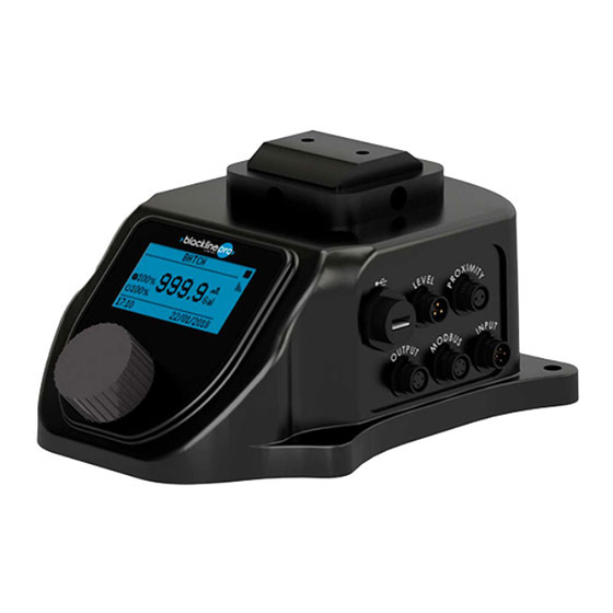
Page 17: Main Components And Dimensions
1. 1 enclosure containing the electronic control unit 2. 1 connection 3. 1 proximity sensor 4. 4 connectors with a 1-meter cable BL2.0 CONNECTION RGB DISPLAY Figure 3 Front view File: UT-5601 Copyright © - OBL Metering pumps - All rights reserved... - Page 18 Figure 4 Side view of the supply lines BL2.0 CONNECTION KNOB STROKE COUNTER SENSOR INPUT CONNECTOR USB CONNECTOR MODBUS CONNECTOR OUTPUT CONNECTOR LEVEL CONNECTOR Figure 5 Side view of the supply lines File: UT-5601 Copyright © - OBL Metering pumps - All rights reserved...
-
Page 19: Environmental Conditions
AND REMOVED FOR R) Figure 7 stroke counter sensor and ring ENVIRONMENTAL CONDITIONS As for installation, the environmental conditions must match the possible use conditions of OBL’s metering pumps, which can be combined with the KIT PRO. This product shall be u sed in Pollution degree 2 Environment. -
Page 20: Technical Data
TECHNICAL DATA The KIT PRO is suitable for all OBL’s metering pumps of the Black Line series with a standard motor (three-phase power supply 230/380V 50 Hz). Contact an OBL distributor in the event motors with different characteristics are installed. -
Page 21: Use And Software
2 ICONS The icons used in the program and relative function are summarised in the following table: Table 5 Icons ICON FUNCTION Main Menu File: UT-5601 Copyright © - OBL Metering pumps - All rights reserved... -
Page 22: Menu
From the home page, click “operating modes” to select the operating mode you need. Each mode features an input screen (Figure 9Figure 10) and an operating screen (Figure 10). Figure 9 Input Figure 10 Operating screen File: UT-5601 Copyright © - OBL Metering pumps - All rights reserved... - Page 23 When the pump receives an external input signal sending pulses, it doses CONCENTRATION the liquid based on the concentration PULSE/L (L/PULSE) value liquid TIMEOUT concentration required at destination (Percentage). PULSE/L File: UT-5601 Copyright © - OBL Metering pumps - All rights reserved...
- Page 24 RANGE ALARM Pause-work FLOW RATE The pump alternates pause periods OPERATING PERIOD (MIN) with constant flow rate operation PAUSE PERIOD (MIN) periods whose duration can be set. File: UT-5601 Copyright © - OBL Metering pumps - All rights reserved...
- Page 25 This mode allows you to test the MOTOR POWER pump’s flow rate at the maximum MAXIMUM MOTOR PHASE CURRENT frequency. The pump capacity screen MOTOR FREQUENCY appears at the end of the test. File: UT-5601 Copyright © - OBL Metering pumps - All rights reserved...
- Page 26 Alarm activation with red display. The proximity sensor (supplied) verifies the correct operation of the pump. The firmware stops the pump if the number of strokes is equal to 0 File: UT-5601 Copyright © - OBL Metering pumps - All rights reserved...
- Page 27 START/STOP (YES/NO) Setting for starting or stopping the CONTACT (N.O./N.C.) pump remotely. One single pin is used in this case. The pump starts when the contact is closed and File: UT-5601 Copyright © - OBL Metering pumps - All rights reserved...
- Page 28 INR05 INRUSH Inrush relays broken HARDWARE MOTOR TRI06 TRIP Motor short circuit HARDWARE PRO07 FUNCTIONAL PROXIMITY Motor or Pump block DFL08 FIRMWARE DATA FLASH Data setting error FLASHING File: UT-5601 Copyright © - OBL Metering pumps - All rights reserved...
- Page 29 The first operation to be accomplished is to disable analog mA output: 1) Go to the menu “settings→Analog output” 2) Set the analog output to “NO” clicking on it File: UT-5601 Copyright © - OBL Metering pumps - All rights reserved...
- Page 30 The value the bottom of the screen will change. e. Change the value close to 4 mA to reach the value at the bottom of the screen. 7) To calibrate 20 mA input signal: File: UT-5601 Copyright © - OBL Metering pumps - All rights reserved...
- Page 31 Change the value until the multimeter will measure the desired 20 mA File: UT-5601 Copyright © - OBL Metering pumps - All rights reserved...
- Page 32 Data lenght 8 bit Parity bit N. A. Stop bit Cyclic Redundancy Check (CRC) CRC-16 ID slave address 1 to 247 Modbus paramerters registers Da 40001 a 40058 File: UT-5601 Copyright © - OBL Metering pumps - All rights reserved...
- Page 33 COMMUNICATION EXAMPLE Black Line PRO can communicate with a PLC using MODBUS interface. Examples of communications are described hereinafter: 1. Read Holding Registers (Function Code 03) a. Request: File: UT-5601 Copyright © - OBL Metering pumps - All rights reserved...
- Page 34 The Data Address of the first register. (41003 - 40001 = 03EA hex) 03EA: ▪ 0002: The number of registers written. ▪ 6078: The CRC (cyclic redundancy check) for error checking. File: UT-5601 Copyright © - OBL Metering pumps - All rights reserved...
- Page 35 Value 2=YY/MM/DD 40007 M_24H Time Format Value 0=24h Value 1=12 h 40008 M_UNIT_LH Unit of measure Value 0=L/h Value 1=Gal/h 40009 M_YES_NO Proximity red alarm Value 0=No Value 1=Yes File: UT-5601 Copyright © - OBL Metering pumps - All rights reserved...
- Page 36 Gal/h)*10 40024 M_MINUTE Working time pause-work mode 40025 M_MINUTE Pausetime pause-work mode 40026 DIP_MIN High value current 4-20 analog mA 40027 DIP_MAX Low value current 4-20 mA analog File: UT-5601 Copyright © - OBL Metering pumps - All rights reserved...
- Page 37 Flowrate pause work mode Gal/h)*10 40047 M_CONTACT Contact output relay Value 0=NO Value 1=NC 40048 M_YES_NO Level START contact activation Value 0=No Value 1=Yes 40049 M_YES_NO Level STOP contact activation File: UT-5601 Copyright © - OBL Metering pumps - All rights reserved...
- Page 38 These registers inform the user written only to 0 about alarms according to the position of the bit 41004 BIT 0 "UVG17",//UNDER BUS BIT 1 "UVB18",//UNDER BUS BIT 2 "TOU01",//TIME OUT File: UT-5601 Copyright © - OBL Metering pumps - All rights reserved...
-
Page 39: Maintenance
Routine maintenance includes operations that are carried out based on the operator’s common sense, without following a strict schedule. HAZARD Do not carry out routine maintenance operations on mains-powered equipment. Routine maintenance operations carried out by the user: File: UT-5601 Copyright © - OBL Metering pumps - All rights reserved... -
Page 40: Troubleshooting
TROUBLESHOOTING To make a self-diagnosis of the product, see subchapter “Alarm log”. Contact the manufacturer if you detect defects and/or malfunctions that are not described in this manual. File: UT-5601 Copyright © - OBL Metering pumps - All rights reserved... -
Page 41: Accessories And Spare Parts
We do not recommend using non-original spare parts. If you decide to use them, all the Warranty terms and conditions, if still valid, will be void and null and the Manufacturer will not be held responsible for any damage to people and/or property. File: UT-5601 Copyright © - OBL Metering pumps - All rights reserved... -
Page 42: Additional Instructions
Disposal of substances into sewers or abandoning waste in the environment is strictly prohibited. Contact your local waste disposal service to receive adequate and accurate information regarding disposal. File: UT-5601 Copyright © - OBL Metering pumps - All rights reserved...
Need help?
Do you have a question about the PRO Series and is the answer not in the manual?
Questions and answers