Advertisement
Quick Links
LUXOMAT
Installation and Operating Instruction for
1. Mounting preparations
Work on the 230 V mains supply
may only be carried out by qualified
professionals or by instructed persons
under the direction and supervision
of qualified skilled electrical person-
nel in accordance with electrotechni-
cal regulations.
Disconnect supply before installing!
When in Master/ Slave mode of
operation, the Master-appliance
must always be installed at the
location where there is least
daylight.
2c. Self test cycle
2000
1200
600
200
40
The product enters an initial 60-second
self-test cycle, when the supply is first
connected. The occupancy detector is
ready for operation.
Option:
IR-PD
max
Wall bracket for remote
control IR-PD
ON
OFF
max
ON
IR-PD-Mini
OFF
®
B.E.G.
- Occupancy detectors PD2-M-2C-24V-3A-SM/-FC and PD2-M-2C-24V-RR-SM/-FC
2a. Installation of the LUXOMAT
The detector must be installed on a solid
and level surface. There is no need for
frames.
For mounting remove lens (C) (turn
anticlockwise). Fasten the mounting pod
to the ceiling.
Having connected up the wires in accord-
ance with regulations, secure the detector
with 2 screws as per the illustration above.
In order to assemble the detector outside, the PD2-IP54 base-plate,
which is available as an accessory, must be mounted between the
detector and the surface on which it is to be installed.
120 60 50
A
40
30
15
5
10
3. Putting into operation / Settings
120 60 50
A
Follow-up time for light control
16 10
5
40
The time can be set infinitely variably at between
2
30
15
1
15 seconds and 16 minutes.
5
10
TEST
30
15
Symbol
: impulse < 1sec.
TEST
Symbol
: Test mode
16 10
2000
5
(Every movement switches on the light for a period of 1
2
1200
1
second, switching it off for a period of 2 seconds after
600
TEST
30
15
200
that regardless of the level of brightness.)
40
Twilight-switch
2000
The switch-on value for the light can be set at between
1200
600
10 and 2000 Lux. Using the rotary control, the luminance
200
set points can be set as desired.
40
Symbol :
Night-time operation
Symbol
: Daytime / Night-time operation
Follow-up time for appliance-control
120 60 50
A
The time can be set infinitely variably at between
40
30
5 minutes and 120 minutes. There is a period of delay
15
5
10
prior to switch-on of between 5 - 10 minutes for times set
in excess of 15 minutes.
16 10
Symbol
: Impulse = 1sec.
5
2
A
Symbol
:
Alarm impulse = 1sec.
1
TEST
30
15
2000
1200
Unlocking device
600
200
40
��
Luminance set point
���
����
���
Automatic reading in the current light value
as new luminance set point
R1
Individual light value 2 - 2500 Lux
��
Follow-up time (relay and channel 1)
��� ��
15 sec. up to 30 min.
���
Impulse function (relay and channel 1)
1sec. ON, 9 sec. OFF
Time setting (relay and channel 2)
�
��� ���
5 min. up to 120 min.
���
Impulse function (relay and channel 2)
R2
The voltage-free contact is closed for a period of 2 seconds.
This is followed by a period of idle time of 8 seconds' duration.
50
1500
Lux
Lux
A
Alarm impulse program for appliance control (relay 2)
3
The relay will not close until at least three movements have been
registered over a period of 10 seconds (impulse = 1 second).
Preset / user mode
Fully automatic/semi automatic mode => (see page 2, point 5)
Semi automatic: red LED (flashing),
Fully automatic: red LED on for approx. 3 sec.
50
1500
Resetting when open
Lux
Lux
All values which have been programmed using the remote
control IR-PD are deleted, and those values which have
been set by potentiometer are activated.
Lock device
PD2-M-2C-24V
®
PD2-M-2C-24V-SM
max
ON
OFF
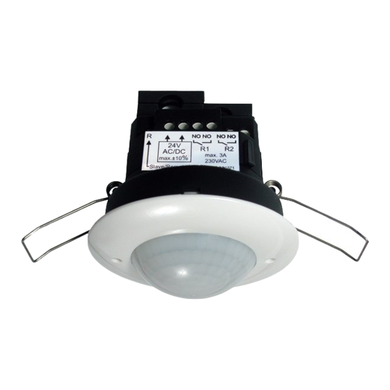
2b. Installation of the LUXOMAT
®
The detector has been designed
and developed specifically for in-
stallation in suspended ceilings.
A circular opening of diameter
68 – 70 mm must be produced in
the ceiling.
Having connected up the cables
in accor dance with regulations,
the detector is inserted into
the opening as shown in the
drawing opposite and fixed into
position with the assistance of
the spring clips.
4. Settings carried out using remote control (optional)
Remote control LUXOMAT
IR-PD
®
120 60 50
A
40
30
15
5
10
1. Check Battery:
open battery compartment by pressing the
120 60 50
A
16 10
plastic springs together and removing the
5
40
2
30
battery-holder.
1
15
5
10
TEST
30
15
1
2
2. IMPORTANT
16 10
2000
5
1200
Please pay attention, that the setting is Potentio-
2
600
1
meter 1 at "TEST" and Potentiometer 2 not at
TEST
200
30
15
40
120 60 50
"SUN". All values which have been programmed
A
40
using the remote control will be deleted in the
30
2000
15
event of power failure in the position "TEST/
5
10
1200
600
1
2
SUN". Please switch Potentiometer 2 over to
200
40
2000
"MOON" or any other value.
16 10
5
1200
2
600
1
200
TEST
30
15
40
Caution:
2000
1200
Settings with remote control supersede the
600
settings by courtesy of potentiometers.
200
40
Lock device
Test mode
Reset to deactivate
Resetting when closed
The lighting relay is switched off, i.e.
opened and the follow-up times reset.
Permanent protection against sabotage
This function blocks the unit permanently (green LED is
illuminated). This operating mode can only be activated
during the period of 5 seconds after pressing the "lock"
button. This status will only permit actuating the function
"Light on/ Light off".
The procedure for leaving this mode is as follows:
1. Switch off the current
2. Apply current for 31 – 59 seconds
3. Switch of the current again
50
1500
Lux
Lux
4. Apply current
5. Open detector
Light on/ off => (see page 2, point 6)
The light will remain switched on/off for as long as move-
ments are detected in the areas of coverage. Once the last
movement has been detected, the light will remain on for
the duration of the follow-up time as per setting.
The appliance will then return independently to the mode
selected (Fully or Semi-automatic).
GB
PD2-M-2C-24V-FC
Advertisement

Related Manuals for B.E.G. LUXOMAT PD2-M-2C-24V


Summary of Contents for B.E.G. LUXOMAT PD2-M-2C-24V
- Page 1 LUXOMAT PD2-M-2C-24V ® B.E.G. Installation and Operating Instruction for - Occupancy detectors PD2-M-2C-24V-3A-SM/-FC and PD2-M-2C-24V-RR-SM/-FC 1. Mounting preparations 2a. Installation of the LUXOMAT ® PD2-M-2C-24V-SM 2b. Installation of the LUXOMAT ® PD2-M-2C-24V-FC Work on the 230 V mains supply The detector must be installed on a solid The detector has been designed may only be carried out by qualified and level surface.
- Page 2 10. Wiring diagrams 13. Technical data PD2-Master-2C-24V 5. Fully / Semi automatic mode (for IR-PD functions see page 1) Sensor and power supply in one case Terminal connection for standard operation Power supply: 24 V AC/DC +6 %/-10 % Fully automatic operation 24V ~ Power consumption: <...
Need help?
Do you have a question about the LUXOMAT PD2-M-2C-24V and is the answer not in the manual?
Questions and answers