Table of Contents
Advertisement
Quick Links
Advertisement
Table of Contents

Related Manuals for Siemens SIWAREX R Construction Elastomer Bearing


Summary of Contents for Siemens SIWAREX R Construction Elastomer Bearing
- Page 1 SIWAREX R Mounting units for BB series Instruction Manual Revision 11/2012...
-
Page 2: Table Of Contents
SIWAREX R Mounting elements for load cells in the BB series Instruction Manual Chapter Overview Warning and Safety Terms ................4 General 5 General Conditions for Installation and Assembly ......7 Lift lock ....................7 Overload Protection ................7 Guide Elements ..................8 Load Cell Dummies ................ - Page 3 Care and Maintenance ............... 24 Ordering Data ....................25 Combi-Mounting Unit ..............26 Technical Description ................. 26 3.1.1 Application Range ..................26 3.1.2 Construction ....................26 3.1.2.1 Construction Combi-Mounting Unit BB 10 - 200 kg ........ 26 3.1.2.2 Combi-Mounting Unit BB 350 / 500 kg ............. 27 Assembly ....................
-
Page 4: Warning And Safety Terms
NOTE means a notice concerning possible advantages of conforming with the recommendation. Copyright © Siemens AG 2012 All rights reserved Disclaimer Circulation or duplication of this document, utilization and We have tested the contents of this document for compatibility disclosure of its contents are not permitted as long as not explicitly with the described hardware and software. -
Page 5: General
All obligations of Siemens result from the sales contract, which also contains the full and solely valid liability agreement. The provisions concerning product liability specified in the sales contract are not extended or limited by the information provided in this document. - Page 6 Brand names / Trademarks ® SIWAREX is a registered trademark of Siemens AG. The other designations in this manual may be trade marks, which if used by third parties, may infringe upon the rights of the proprietor. Document-No.: A5E00295975A Page 6...
-
Page 7: General Conditions For Installation And Assembly
General Conditions for Installation and Assembly Lift lock Lift locks prevent the head plate being lifted from the load cells or permanently mounted load cells from being overloaded by force against the measuring direction. Lift locks are necessary if there is a danger of the load platform being lifted or tipped. -
Page 8: Guide Elements
Revision 11/12 General Conditions for Installation and Assembly Limit stop Limit stop Platform Platform Platform Platform Drill hole Drill hole Bolt Bolt ±2.8 ±2.8 ±2.8 ±4 ±4 Oscillation limiters at a permitted oscillation of 4 mm in a dual weighing platform example. - Page 9 Revision 11/12 General Conditions for Installation and Assembly Fig. 1-3 Guide Positioning Document-No.: A5E00295975A Page 9...
-
Page 10: Load Cell Dummies
Revision 11/12 General Conditions for Installation and Assembly Load Cell Dummies Load cells are sensitive sensors. To protect them from damage, they should only be handled as late as possible for installation and transport. During installation and transport, these should be replaced by dummies or phantoms. Dummies can be constructed as follows for example: 1. -
Page 11: Welding And Installation Work
Revision 11/12 General Conditions for Installation and Assembly Loads must be introduced precisely in the direction of measurement of the load cells. Torsion and bending moments, off-center loading and transverse loads are disturbance forces that lead to incorrect measurements and can cause damage if exceeding the permitted limitations of the load cells and mounting elements. -
Page 12: Installation Surfaces
Revision 11/12 General Conditions for Installation and Assembly DANGER Contaminated, icy or incorrectly set overload protection will create blockages which cause incorrect measurements or can cause injury or damage to the machinery by overloading the scale. CAUTION Proper assembly and installation of load cells and mounting elements is to be ensured by checking the assembly dimensions and freedom of movement for example. -
Page 13: Dismantling
Revision 11/12 General Conditions for Installation and Assembly 2. Mounting point height adjustment The output signals of all load cells are determined one after the other when they are loaded. In order to achieve similar loading on all of them, spacer plates are used to adjust the height. -
Page 14: Elastomer Bearing
Elastomer Bearing Technical Description 2.1.1 Application Range The elastomer bearing is used for protecting the load cells if there is the possibility of having to deal with jolts or oscillation. This has a self-centering effect on the load platform. In combination with the base plate, this is a simple solution for load cell assembly. -
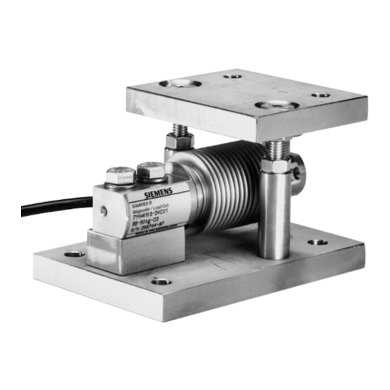
Page 15: Construction Elastomer Bearing Bb 350 / 500 Kg
Revision 11/12 Elastomer bearing 2.1.2.2 Construction Elastomer Bearing BB 350 / 500 kg A complete elastomer bearing unit consists of basic order-components base plate with overload protection, load cell, oscillation housing and elastomer bearing. The base plate (1) is bolted to the foundation with four bolts. The load cell (3) is fastened to the base plate with two Allen Screws (5) and the spacer bar (2). -
Page 16: Assembly
Revision 11/12 Elastomer bearing Assembly The conditions for installation are very different. The load platform can be very low or relatively high. It could be a container, a platform or a conveyor for example. The following assembly instructions can only be taken as general guidelines. WARNING Proper tools are to be used for lifting the load platform. - Page 17 Revision 11/12 Elastomer bearing Bolt the elastomer bearing (10) to the load cell (3) with the hexagon bolt (8) and the washer (9). Hold the elastomer bearing (10) down when tightening the hexagon bolt (8) to prevent damage being done to the load cell. The arrow on the front of the load cell indicates the direction of measurement.
- Page 18 Revision 11/12 Elastomer bearing Fig. 2-3 Assembly Elastomer Bearing BB 10 - 200 kg 6. Setting the overload protection: Load the loading platform with the maximum applicable load. Set the overload protection mechanism (7) in connection with the nut (6) to 0.05 - 0.1 mm, see dimension X in Fig.
-
Page 19: Assembly Elastomer Bearing Bb 350 / 500 Kg
Revision 11/12 Elastomer bearing DANGER Contaminated, icy or incorrectly set overload protection will create blockages which cause incorrect measurements or can cause injury or damage to the machinery by overloading the scale. 2.2.2 Assembly Elastomer Bearing BB 350 / 500 kg Assembly procedures: (Numbering see Fig. - Page 20 Revision 11/12 Elastomer bearing 6. Install the elastomer bearing unit: Loosen the bolts on the dummies Lift the loading platform from the first bracket and remove the dummy. Install the elastomer bearing unit and screw the bolts in loosely. ...
-
Page 21: Technical Data
Revision 11/12 Elastomer bearing 7. Setting the overload protection: Load the loading platform with the maximum applicable load. Set the overload protection mechanism (7) in connection with the nut (6) to 0.05 - 0.1 mm, see dimension X, Fig. 2-6, is. ... -
Page 22: Dimensions
Revision 11/12 Elastomer bearing 2.3.2 Dimensions Fig. 2-7 Dimensions BB 10 - 200 kg Document-No.: A5E00295975A Page 22... - Page 23 Revision 11/12 Elastomer bearing Fig. 2-8 Dimensions BB 350 / 500 kg Document-No.: A5E00295975A Page 23...
-
Page 24: Care And Maintenance
Revision 11/12 Elastomer bearing Care and Maintenance General The physical properties of most rubber goods will change in adverse conditions or if improperly handled. Rubber components can become unusable when it becomes too soft or too hard, gets deformed or cracks, peels or has any other surface damage. The changes can be caused by the effects of e.g. -
Page 25: Ordering Data
Revision 11/12 Elastomer bearing Ordering Data Elastomer bearing Order number Order number Order number for load cells with a Elastomer bearing Base plate Oscillation nominal load of housing 10 - 50 kg 7MH4 133-2KE11 7MH4 133-3DG11 100 - 200 kg 7MH4 133-3DE11 7MH4 133-3DG11 350 / 500 kg... -
Page 26: Combi-Mounting Unit
Combi-Mounting Unit Technical Description 3.1.1 Application Range Combi-mounting units are for direct force transmission to the load cells. These are self-centering on the load platform. The combi-mounting units have the following features: Integrated oscillation limitation. Integrated lift protection with the BB 10 - 200 kg. ... -
Page 27: Combi-Mounting Unit Bb 350 / 500 Kg
Revision 11/12 Combi-Mounting Units No. Designation Designation 1 Base plate 10 Overload protection 2 Spacer bar 11 Retaining ring 3 Load cell 12 Oscillation housing 4 Washer 13 Pressure piece 5 Hexagon head screw 14 Flat seal 6 Nut 15 Pressure piece 7 Half-nut 16 Oscillation bolt 8 Countersunk screw... -
Page 28: Assembly
Revision 11/12 Combi-Mounting Units No. Designation Designation 1 Base plate 9 Pressure piece load cell 2 Spacer bar 10 Ball 3 Load cell 11 Pressure piece head plate 4 Washer 12 Head plate 5 Cylinder head screw 13 Nut 6 Ground cable 14 Washer 7 Hexagon head screw 15 Countersunk screw... - Page 29 Revision 11/12 Combi-Mounting Units Assembly procedures: (Numbering see Fig. 3-3) Load cell preparation: A data sheet is supplied with every load cell with the calibration values for that load cell. This is found in a supply pocket which is stuck on the packaging. Take the data sheet and store it in a safe place.
- Page 30 Revision 11/12 Combi-Mounting Units DANGER A falling loading platform can result in death, severe injury or damage to equipment depending on exposure. Insert the oscillation housing (12) into the load cell (3). The arrow on the front of the load cell indicates the direction of measurement. ...
- Page 31 Revision 11/12 Combi-Mounting Units Fig. 3-3 Assembly Combi-Mounting Unit BB 10 - 200 kg Installing the Combi-Mounting Unit: Loosen the bolts on the dummies. Lift the loading platform from the first bracket and remove the dummy. Set the combi-mounting unit in place and loosely install the fastening bolts. ...
-
Page 32: Combi-Mounting Unit Bb 350 / 500 Kg
Revision 11/12 Combi-Mounting Units Setting the overload protection: Load the loading platform with the maximum applicable load. Set the overload protection mechanism (10) in connection with the nut (9) to 0.05 - 0.1 mm, see dimension X in Fig. 3-4. ... - Page 33 Revision 11/12 Combi-Mounting Units Combi-Mounting Unit preparation: NOTE The lifting distance of the head plate (12) must be set to approximately 3 mm, see dimension X in Fig. 3.8. Setting this lifting distance is easier if performed before installing the load cell. The combi-mounting unit must be disassembled in order to install the load cell.
- Page 34 Revision 11/12 Combi-Mounting Units Put the load cell (3) on the spacer bar (2) using 2x Allen screws (5) and 2x washers (4). The arrow on the front of the load cell indicates the direction of measurement, see Fig. 3-6. ...
-
Page 35: Technical Data
Revision 11/12 Combi-Mounting Units Installing the Combi-Mounting Unit: Loosen the bolts on the dummies. Lift the loading platform from the first bracket and remove the dummy. Set the combi-mounting unit in place and loosely install the fastening bolts. ... -
Page 36: Dimensions
Revision 11/12 Combi-Mounting Units 3.3.2 Dimensions Fig. 3-9 Dimensions Combi-Mounting Unit BB 10 - 200 kg Document-No.: A5E00295975A Page 36... - Page 37 Revision 11/12 Combi-Mounting Units Fig. 3-10 Dimensions Combi-Mounting Unit BB 350 / 500 kg Document-No.: A5E00295975A Page 37...
-
Page 38: Care And Maintenance
Revision 11/12 Combi-Mounting Units Care and Maintenance Combi-mounting units are to be inspected depending on the environmental conditions. If there is a high degree of dust, contamination, humidity etc., the maintenance intervals are to be chosen respectively. These are to be kept free of course contamination. The flat seal may not be subjected to direct streams of water. -
Page 39: Ground Cable
Ground cable Technical Description 4.1.1. Application Range The ground cable is used for protecting the load cells from unwanted currents. These currents could be cause by e.g.: as equalization currents for missing or faulty, voltage equalization lines, a lightning bolt in the vicinity, ... -
Page 40: Dimensions
Revision 11/12 Ground cable Dimensions Fig. 4-2 Dimensions Ground Cable Care and Maintenance The connections of the cable are to be inspected regularly for corrosion and conductivity. Ordering Data Designation Order number Ground cable 7MH3 701-1AA1 Document-No.: A5E00295975A Page 40...