Table of Contents
Advertisement
AQUABOOST
Installation, Operation & Maintenance
Instructions
Please leave this instruction booklet in a safe place as it contains
important warranty, maintenance and safety information
Read this manual carefully before commencing installation.
This manual covers the following products:
Model
iBolt Pump
iBolt Single Pump Booster Set
iBolt Twin Pump Booster Set
Please note images are representative only and may not portray
your model
Advertisement
Table of Contents

Related Manuals for Stuart Turner AQUABOOST iBolt Pump


Summary of Contents for Stuart Turner AQUABOOST iBolt Pump
- Page 1 AQUABOOST Installation, Operation & Maintenance Instructions Please leave this instruction booklet in a safe place as it contains important warranty, maintenance and safety information Read this manual carefully before commencing installation. This manual covers the following products: Model iBolt Pump iBolt Single Pump Booster Set iBolt Twin Pump Booster Set Please note images are representative only and may not portray...
-
Page 2: Table Of Contents
CONTENTS 1 PRODUCT OVERVIEW .................... 1 2 WARNINGS ......................2 3 CHECKLIST ......................4 4 IMPORTANT - READ BEFORE COMMENCING INSTALLATION ......7 5 LOCATION - GENERAL ..................8 6 KEY FEATURES ......................9 7 INSTALLATION & CONNECTIONS ................. 12 8 ELECTRICAL INSTALLATION & EARTHING ............13 9 COMMISSIONING &... -
Page 3: Product Overview
PRODUCT OVERVIEW Product Description The iBolt range consists of a single pump unit and single and twin pump booster sets comprising centrifugal pump(s) and electronic control. Application The Aquaboost iBolt range is designed to meet the demand of pressurised systems in domestic applications where the existing mains water supply is insufficient. -
Page 4: Warnings
WARNINGS • This pump/pump set must not be used for any other application without the written consent of Stuart Turner Limited. • This appliance can be used by children aged from 8 years and above and persons with reduced physical, sensory or mental... - Page 5 • Before starting work on the electrical supply ensure power supply is isolated. • DO NOT allow the supply cord to contact hot surfaces, including the motor shell, pump body or pipework. The cord should be safely routed and secured by cable clips. •...
-
Page 6: Checklist
CHECKLIST IMPORTANT: With the appliance removed from its packaging check for any damage prior to installation. If any damage is found contact Stuart Turner Ltd within 24 hours of receipt. iBolt Pump Figure 1 Item Description iBolt pump Instruction guide... - Page 7 iBolt Single Pump Booster Set Figure 2 Item Description iBolt booster set Instruction guide Your product may vary slightly from the illustration above.
- Page 8 iBolt Twin Pump Booster Set Figure 3 Item Description iBolt booster set Instruction guide Your product may vary slightly from the illustration above.
-
Page 9: Important - Read Before Commencing Installation
IMPORTANT - READ BEFORE COMMENCING INSTALLATION Water Temperature This unit is designed to pump cold water only which should not exceed the following values: The maximum allowable water temperature is 23 °C. The minimum allowable water temperature is 4 °C. Pipework - General Do not drill holes or put fastenings into the iBolt tank, this will cause leakage. -
Page 10: Location - General
LOCATION - GENERAL • Access: For emergencies and maintenance the pump must be easily accessible. • Protection: The iBolt must be located in a dry, frost free area. The iBolt must not be installed in a loft space. • Ventilation: Ensure an adequate air flow to cool the iBolt. Separate the iBolt from other appliances that generate heat. -
Page 11: Key Features
KEY FEATURES iBolt Pump Figure 4 ITEM DESCRIPTION iBolt Pump & Variable Speed Controller... - Page 12 iBolt Single Pump Booster Set Figure 5 ITEM DESCRIPTION iBolt Pump & Variable Speed Controller Nipple Non Return Valve Union Ball Valve 5 Way Connector Isolation & Drain Valve Pressure Gauge M / F Union 8 Litre Pressure Vessel Base Plate Union Ball Valve Pressure Transducer Isolation Valve...
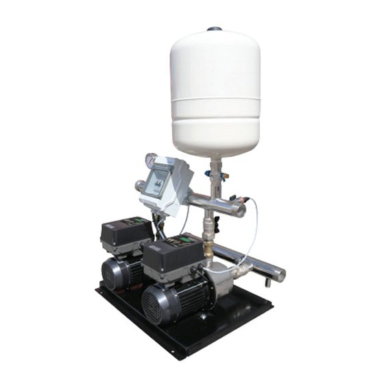
- Page 13 iBolt Twin Pump Booster Set Figure 6 ITEM DESCRIPTION ITEM DESCRIPTION Base Plate Flow Through Isolating & Drain Valve iBolt Pump & Variable Speed 24 Litre Pressure Vessel Controller Suction Manifold Isolation Valve Union Ball Valve Pressure Transducer Nipple Plug Non Return Valve Junction Box Union Ball Valve...
-
Page 14: Installation & Connections
INSTALLATION & CONNECTIONS Water Connection The iBolt is to be permanently connected to a cold water storage tank using rigid pipe or suitably sized and rated flexible hose to comply with current building and plumbing regulations. Ensure there is a demountable joint in the pipe to allow the removal of the iBolt if needed. -
Page 15: Electrical Installation & Earthing
ELECTRICAL INSTALLATION & EARTHING Regulations • The electrical installation must be carried out in accordance with the current national electrical regulations and installed by a qualified person. Safety • RCD’s/ELCB’s are not recommended for use with variable speed drives/motors. If an RCD is mandatory use type B RCDs. •... - Page 16 Adjacent Pipes • Adjacent suction and delivery pipes should be fitted with earthing clamps in accordance with current regulations (Figure 7 Earth continuity connections). Figure 7 Earthing • This appliance must be earthed via the supply cord, which must be correctly connected to the earth point located in the terminal box.
- Page 17 8.10 Wiring of Connection Unit • WARNING: This appliance must be earthed. • The wires in the mains lead (supply cord) are coloured in accordance with the following code: Green and Yellow: Earth Blue: Neutral Brown: Live As the colours of the wires in the mains lead of this appliance may not correspond with the coloured markings identifying the terminals in your connection unit proceed as follows: The wire which is coloured green and yellow must be connected...
- Page 18 8.11 Wiring Diagrams Connection Master & Slave Communication, Pressure Transducer and External Level Sensor Use cables with reinforced isolation. 1. Unscrew the cover and loosen the PG located on the lateral side of the plastic body. 2. Insert the cord through the PG. 3.
- Page 19 iBolt (Twin Controller) Figure 9...
- Page 20 If the supply cord is to be changed or is damaged, it must be replaced with a special cord assembly available from Stuart Turner or one of their approved repairers. On disassembly note the cord retention and routing system. Re-assemble to the same pattern.
-
Page 21: Commissioning & Starting
COMMISSIONING & STARTING Pump Controller Figure 10 LCD screen. Shows the pressure in working mode. MANUAL START-STOP pushbutton. Pushbutton for ENTER or EXIT menu. Pushbuttons for changing programming values showed in the LCD screen (1). ENTER for saving programmed values. Every press is succeeded by a new field of the CONFIGURATION MENU. - Page 22 the pump stopped or when the device is not connected. AUTOMATIC green: it is bright in AUTOMATIC mode. When it is intermittent in MASTER&SLAVE mode it means that this device will be auxilliary in the following cycle. ON/OFF: Change from AUTOMATIC to MANUAL mode or vice versa. Operation Automatic control device designed for single and three-phase pump’s automation, with an electronic system managed by software responding to the rigorous...
- Page 23 • Possibility of communication with another device to operate in MASTER & SLAVE regime. • Control panel Display with back light for alarm menu with permanent pressure indication as digital gauge. START/STOP push-button to manually start and stop the pump. ENTER pushbutton to save data in memory.
- Page 24 Start Up (Single Pump Unit) 1. Be sure that the pump is correctly primed. 2. Connect the device to the electric supply with the magnetothermic switch FAILURE led light will be ON. Wait for 10 seconds while the device is doing the autotest.
- Page 25 Configuration Use ▲▼ to change the values and press ENTER for validation. To quit the configuration sequence press MENU. After every press of the ENTER key the different screens that constitute the configuration sequence will be displayed To start the sequence of configuration press MENU during 3”...
- Page 26 SYSTEM OPERATING PRESSURE Use keys ▲▼ to modify the initial value (2 bar). WARNING: The input pressure must be at least 1 bar lower than the maximum pressure of the pumps. NOTE: In case of twin pump systemsl the system operates at the pressure set in the MASTER device, so that the configuration of set pressure in the slave device has no effect.
- Page 27 Screen Display Being the unit in automatic mode (LED AUTO ON) by pressing ▲ can be displayed several operation parameters. Where: 1. Pset is the set pressure or target pressure in bar. 2. Pbar is the instantaneous lecture of pressure in bar. 3.
- Page 28 Expert Menu There is normally no need to adjust these values, they are factory set. Using ▲▼ we can change the values and press ENTER for validation. To quit the configuration sequence press MENU. After every ENTER the messages of the configuration sequence will be displayed.
- Page 29 System Flushing • The pipework system should be flushed out prior to the iBolt being connected to ensure any contaminants/chemical residues and foreign bodies are removed from elsewhere in the system. Water Supply Always ensure that water supply is adequate to meet the demand. Ensure the pump chamber is full of water before starting the pump.
- Page 30 4. Carefully check pump and pipework for leaks whilst pump running and stationary before leaving the installation unattended. 9.12 For Further Technical Support Phone the Stuart Turner TechAssist team on +44 (0) 800 31 969 80. Our staff are trained to help and advise you over the phone.
-
Page 31: Maintenance
MAINTENANCE 10.1 Pressure Vessel The pressure vessel should be checked once every 12 months to have its pre- charge checked or replenished, this should be carried out as follows: 1. Isolate pump electrically. 2. Remove the front cover. 3. Isolate the water supply by closing the appropriate isolating valves. 4. -
Page 32: Trouble Shooting
TROUBLE SHOOTING 11.1 Alarms (Single Pump Systems) In case of simultaneous alarms, quit the automatic mode and go to manual mode, pressing the pushbutton AUTOMATIC ON/OFF (led light PUMP will turn off). Using key ▲▼ will be displayed the succesive alarms. Once visualized, for leaving the menu, press ENTER returning to MANUAL mode. - Page 33 A2 OVER-INTENSITY ☼ Failure verification Final failure DESCRIPTION: the pump is protected against over currents by mean of the intensity values established in the installation menu. These over currents are produced generally by dysfunctions in the pump or in the electric supply. SYSTEM REACTION: when detecting the thermal failure, the pump will be automatically stopped.
- Page 34 A6 EXCESSIVE TEMP Final failure DESCRIPTION: the system is cooled by the motor fan to keep the INVERTER in optimum working conditions. SYSTEM REACTION: if an excessive temperature is reached the own system leaves the inverter out of service and as consequence the pump too. SOLUTION: verify the temperature environment should be under 50 ºC.
- Page 35 11.2 Alarm Installation Master-Slave A10 COMUNICA (Failure verification) DESCRIPTION: If you have configured a Master-Slave system and communication cable is disconnected or there is a bad connection, the system stops. SYSTEM REACTION: The Master-Slave system stops and starts to operate individually.
- Page 36 11.4 Register of Operational Data and Alarms By using simultaneously MENU + during 3” is acceded to register of operation data and alarms, by mean of ENTER we can advance through the sequence, once finished the sequence we come back to the main display. Sequence: REGISTER HOURS Counter of total time that the pump has been operating.
-
Page 37: Product Warranty
+44 (0) 800 31 969 80 You should obtain appropriate insurance cover for any loss or damage which is not covered by Stuart Turner Ltd in this provision. Please record here for your reference: TYPE NO. SERIAL NO. - Page 38 NOTES:...
- Page 39 NOTES:...
-
Page 40: Declaration Of Conformity
STUART TURNER LIMITED HENLEY-ON-THAMES, OXFORDSHIRE RG9 2AD ENGLAND. Signed ................Engineering Manager Stuart Turner are an approved company to BS EN ISO 9001:2015 Stuart Turner Ltd, Henley-on-Thames, Oxfordshire RG9 2AD ENGLAND Tel: +44 (0) 1491 572655 Fax: +44 (0) 1491 573704 info@stuart-turner.co.uk www.stuart-turner.co.uk...
Need help?
Do you have a question about the AQUABOOST iBolt Pump and is the answer not in the manual?
Questions and answers