Table of Contents
Advertisement
Quick Links
AQUABOOST
Installation, Operation & Maintenance
Instructions
Please leave this instruction booklet in a safe place as it contains
important guarantee, maintenance and safety information
Read this manual carefully before commencing installation.
This manual covers the following products:
Model
iMatic 0304 1S-CMT/8 450
iMatic 0304 2S-CMT/24 800
iMatic 0504 2S-CMT/24 1200
Please note images are representative only and may not portray
your model
Part No
47359
47360
47361
Advertisement
Table of Contents

Related Manuals for Stuart Turner AQUABOOST iMatic 0304 1S-CMT/8 450


Summary of Contents for Stuart Turner AQUABOOST iMatic 0304 1S-CMT/8 450
- Page 1 AQUABOOST Installation, Operation & Maintenance Instructions Please leave this instruction booklet in a safe place as it contains important guarantee, maintenance and safety information Read this manual carefully before commencing installation. This manual covers the following products: Model Part No iMatic 0304 1S-CMT/8 450 47359 iMatic 0304 2S-CMT/24 800...
-
Page 2: Table Of Contents
CONTENTS 1 PRODUCT OVERVIEW .................... 1 2 WARNINGS ......................2 3 CHECKLIST ......................4 4 IMPORTANT - READ BEFORE COMMENCING INSTALLATION ......6 5 LOCATION - GENERAL ................... 7 6 KEY FEATURES ....................... 8 7 INSTALLATION & CONNECTIONS ................. 10 8 ELECTRICAL INSTALLATION & EARTHING ............12 9 COMMISSIONING &... -
Page 3: Product Overview
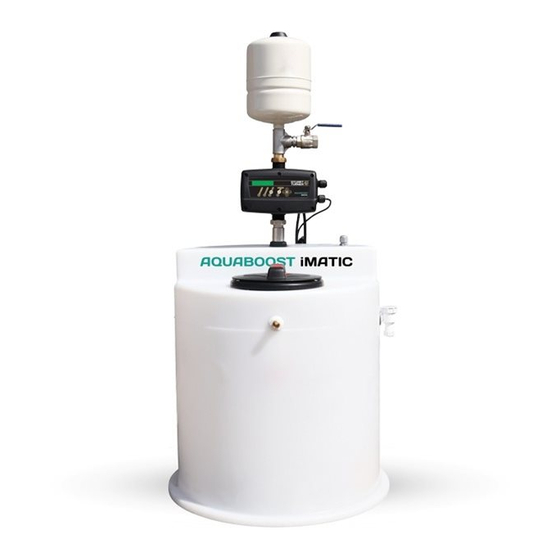
PRODUCT OVERVIEW Product Description The iMatic range is a water pressure and flow booster set with integral water storage tank and electric motor driven centrifugal pump complete with an automatic control system, consisting of flow switch, pressure switch, pressure vessel and electronic control. The design of the tank incorporates an AC air gap for fluid isolation (BS EN 1717). -
Page 4: Warnings
WARNINGS • This pump set must not be used for any other application without the written consent of Stuart Turner Limited. • This appliance can be used by children aged from 8 years and above and persons with reduced physical, sensory or mental... - Page 5 • Before starting work on the electrical supply ensure power supply is isolated. • DO NOT allow the supply cord to contact hot surfaces, including the motor shell, pump body or pipework. The cord should be safely routed and secured by cable clips. •...
-
Page 6: Checklist
CHECKLIST IMPORTANT: With the appliance removed from its packaging check for any damage prior to installation. If any damage is found contact Stuart Turner Ltd within 24 hours of receipt. iMatic Single Pump Booster Set Figure 1 Item Description iMatic Single Set Instruction guide Your product may vary slightly from the illustration above. - Page 7 iMatic Twin Pump Booster Set Figure 2 Item Description iMatic Twin Set Instruction guide Your product may vary slightly from the illustration above.
-
Page 8: Important - Read Before Commencing Installation
IMPORTANT - READ BEFORE COMMENCING INSTALLATION Water Storage Capacity The iMatic usable water volume can be found in the technical specification table (Section 8); the length of time the iMatic delivers water will be dependent on the usage and refill rates Water Temperature This unit is designed to pump cold water only which should not exceed the following values:... -
Page 9: Location - General
LOCATION - GENERAL • Access: For emergencies and maintenance the pump must be easily accessible. • Protection: The iMatic must be located in a dry, frost free area. The iMatic must not be installed in a loft space. • Ventilation: Ensure an adequate air flow to cool the iMatic. Separate the iMatic from other appliances that generate heat. -
Page 10: Key Features
KEY FEATURES iMatic Single Pump Booster Set Figure 3 ITEM DESCRIPTION 450 Litre Tank – Fitted with Inlet and Overflow Tank Connector Nut Reducing Bush M/F Union iMatic Controller Nipple 8 Litre Pressure Vessel Ball Valve Tank Connector Tank Connector Rubber Seal F/F Union PVC Pipe Reducing Nipple... - Page 11 iMatic Twin Pump Booster Set Figure 4 ITEM DESCRIPTION ITEM DESCRIPTION 800 Litre Tank – Fitted with Pressure Gauge Inlet and Overflow Tank Connector Nut Reducing Bush Reducing Bush Small Cap for manifold ports M/F Union Small Plug for manifold ports iMatic Controller Tank Connector Ball Valve...
-
Page 12: Installation & Connections
INSTALLATION & CONNECTIONS Mains Water Connection The iMatic is to be permanently connected to the mains water supply using rigid pipe or suitably sized and rated flexible hose to comply with current building and plumbing regulations. The water tank fill valve has a G ½ male threaded fitting; a suitable 90 elbow type fitting must be used. - Page 13 Unit Location The iMatic is intended to be installed as a freestanding unit with its back to a wall. 1. Slide the iMatic into position in front of the services leaving approximately 20 mm gap between the iMatic and the wall behind. 2.
-
Page 14: Electrical Installation & Earthing
ELECTRICAL INSTALLATION & EARTHING Regulations • The electrical installation must be carried out in accordance with the current national electrical regulations and installed by a qualified person. Safety • RCD’s/ELCB’s are not recommended for use with variable speed drives/motors. If an RCD is mandatory use type B RCD’s. •... - Page 15 Adjacent Pipes • Adjacent suction and delivery pipes should be fitted with earthing clamps in accordance with current regulations (Figure 10). Figure 5 Earthing • This appliance must be earthed via the supply cord, which must be correctly connected to the earth point located in the terminal box.
- Page 16 8.10 Wiring of Connection Unit • WARNING: This appliance must be earthed. • The wires in the mains lead (supply cord) are coloured in accordance with the following code: Green and Yellow: Earth Blue: Neutral Brown: Live As the colours of the wires in the mains lead of this appliance may not correspond with the coloured markings identifying the terminals in your connection unit proceed as follows: The wire which is coloured green and yellow must be connected...
- Page 17 8.11 Wiring Diagrams iMatic (Twin Controller) Figure 6...
- Page 18 If the supply cord is to be changed or is damaged, it must be replaced with a special cord assembly available from Stuart Turner or one of their approved repairers. On disassembly note the cord retention and routing system. Re-assemble to the same pattern.
-
Page 19: Commissioning & Starting
COMMISSIONING & STARTING Control Panel Figure 7 LCD screen. Shows the pressure in working mode. MANUAL START-STOP pushbutton. Pushbutton for ENTER or EXIT menu. Pushbuttons for changing programming values showed in the LCD screen (1). ENTER for saving programmed values. Every press is succeeded by a new field of the CONFIGURATION MENU. - Page 20 Start Up (Single Controller) Be sure that the pump is correctly primed. FAILURE led light will be ON. Wait for 10 seconds while the iMatic conducts an autotest. Once it finishes, led light FAILURE is OFF and led light LINE is ON. The LCD screen will show message “IMATIC”...
- Page 21 Configuration Using we can change the values and press ENTER for validation. To quit the configuration sequence at any time press MENU. After every ENTER the different screens that constitute the configuration sequence will appear. P LINE INPUT P To start configuration sequence press MENU during 3”.
- Page 22 PROGRAMMING Being inside configuration menu we have access to the phase of programming. SET PRESSURE 2.0 bar This will be the system operating pressure. Use keys to modify the initial value (2 bar). WARNING ! The input pressure must be al least 1 bar lower than the maximum pressure of the pumps.
- Page 23 VIEW MODE NORMAL There are 2 view modes to choose: - NORMAL: it is visualized “P LINE” (real pressure of the installation) and “INPUT P” (configured pressure). - SERVICE: it is visualized “Hz” (working frequency of the inverter), “REF” (configured pressure), “PRESS” (real pressure of the installation) y “FL” (flow sensor state).
- Page 24 System Flushing • The pipework system should be flushed out prior to the iMatic being connected to ensure any contaminants/chemical residues and foreign bodies are removed from elsewhere in the system. Water Supply Always ensure that water supply is adequate to meet the demand. Ensure the pump chamber is full of water before starting the pump.
- Page 25 4. Carefully check pump and pipework for leaks whilst pump running and stationary before leaving the installation unattended. For Further Technical Support Phone the Stuart Turner TechAssist team on +44 (0) 800 31 969 80. Our staff are trained to help and advise you over the phone.
-
Page 26: Maintenance
MAINTENANCE 10.1 Pressure Vessel The pressure vessel should be checked once every 12 months to have its pre- charge checked or replenished, this should be carried out as follows: 1. Isolate pump electrically. 2. Remove the front cover. 3. Isolate the water supply by closing the appropriate isolating valves. 4. - Page 27 10.4 Draining the tank The tank can be drained by either: 1. Isolating the mains water supply to the fill valve and using the pump to pump the water out of the tank. 2. Isolating the water supply to the tank and attaching a flexible hose to the drain valve.
-
Page 28: Technical Specification
TECHNICAL SPECIFICATION iMatic 450 iMatic 800 iMatic 1200 Model 46668 46711 47361 General Warranty 1 year Approvals Features Water tank air gap Type AF Fluid category Cat 3, Cat 4 Pump control system Variable speed Pump control mode Duty-Assist or Duty-Standby (twin pump) Dry run protection ... - Page 29 Filled 425 Kg 725 Kg 1025 Kg Stuart Turner reserve the right to amend the specification without notice. *Assumes 1 bar inlet pressure. Noise The equivalent continuous A-weighted sound pressure level at a distance of 1 metre from the front of the unit is less than 58 dB(A).
-
Page 30: Trouble Shooting
TROUBLE SHOOTING 12.1 Alarms (Single Pump Systems) In case of simultaneous alarms, quit the automatic mode and go to manual mode by pressing AUTOMATIC ON/OFF (led light PUMP will turn off). Using keys will be displayed the succesive alarms. Once visualised, to quit the menu, press ENTER returning to MANUAL mode. - Page 31 A2 OVER-INTENSITY Failure verification Final failure The system pumps are protected against over currents by mean of the intensity values established in the installation menu. These over currents are produced generally by dysfunctions in the pump or in the electric supply. When detecting the thermal failure, the pump will be automatically stopped.
- Page 32 The pump remains stopped for 10". Then it starts again - 4 attempts. If the problem is not solved, the pump will remain definitively out of order. Check the pump, if the problem persists, contact Stuart Turner technical services. A8 OVERVOLTAGE ...
- Page 33 12.2 Alarms - Twin Pump Systems The alarms are similar to those of single pump systems with the specific particularities of operation with two controllers. Depending on the system’s reaction there are 4 types of alarm: 1. Communication Failure No alarm is activated. Both devices continue operating independently. 2.
- Page 34 12.3 Register of Operational Data and Alarms By using simultaneously MENU + during 3” is acceded to register of operation data and alarms, by mean of ENTER we can advance through the sequence, once finished the sequence we come back to the main display. Sequence: REGISTER HOURS Counter of total time that the pump has been operating.
-
Page 35: Product Warranty
+44 (0) 800 31 969 80 You should obtain appropriate insurance cover for any loss or damage which is not covered by Stuart Turner Ltd in this provision. Please record here for your reference: TYPE NO. SERIAL NO. -
Page 36: Declaration Of Conformity
STUART TURNER LIMITED HENLEY-ON-THAMES, OXFORDSHIRE RG9 2AD ENGLAND. Signed ................Engineering Manager Stuart Turner are an approved company to BS EN ISO 9001:2015 Stuart Turner Ltd, Henley-on-Thames, Oxfordshire RG9 2AD ENGLAND Tel: +44 (0) 1491 572655 Fax: +44 (0) 1491 573704 info@stuart-turner.co.uk www.stuart-turner.co.uk...
Need help?
Do you have a question about the AQUABOOST iMatic 0304 1S-CMT/8 450 and is the answer not in the manual?
Questions and answers