Table of Contents
Advertisement
Quick Links
Installation, Operation & Maintenance
Instructions
Please leave this instruction booklet with the home owner as it contains
important guarantee, maintenance and safety information
Read this manual carefully before commencing installation.
This manual covers the following products:
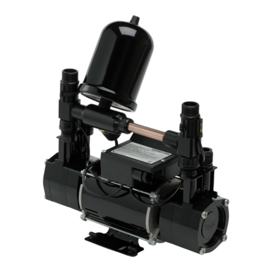
Universal 1.8 bar Twin ended shower pump - ST NH PUMP 18TN
FOR POSITIVE OR NEGATIVE HEAD APPLICATIONS
Advertisement
Table of Contents

Related Manuals for Stuart Turner ST NH PUMP 18TN


Summary of Contents for Stuart Turner ST NH PUMP 18TN
- Page 1 Please leave this instruction booklet with the home owner as it contains important guarantee, maintenance and safety information Read this manual carefully before commencing installation. This manual covers the following products: Universal 1.8 bar Twin ended shower pump - ST NH PUMP 18TN FOR POSITIVE OR NEGATIVE HEAD APPLICATIONS...
- Page 2 PRODUCT DESCRIPTION Electric motor driven single or twin ended peripheral pumps complete with an automatic control system, consisting of flow switches, pressure switch, pressure vessel and electronic control. APPLICATION Universal 1.8 bar pumps are suitable for positive or negative head installation conditions. The pumps are designed for single or multiple (up to 4) outlet pressure boosting applications in vented stored water systems.
-
Page 3: Table Of Contents
STORAGE If this product is not to be installed immediately on receipt, ensure that it is stored in a dry, frost and vibration free location in its original packaging. CONTENTS Page Checklist ............4 Pre-Installation . -
Page 4: Checklist
CHECKLIST IMPORTANT: With the pump removed from its packaging check for any damage prior to installation. If any damage is found contact Bristan within 24 hours of receipt. Fig. 1 Item Description Qty Item Description Pump ISO Hose & integral washer 2(1) Plain Hose &... -
Page 5: Important Facts - Read Before Commencing Installation
1 IMPORTANT FACTS: READ BEFORE COMMENCING PUMP INSTALLATION A. Water storage capacity. 1.11 The hot and cold water storage capacity must be sufficient to meet the flow rates required by the pumped equipment and any other water using fittings and appliances, which may be operated simultaneously. -
Page 6: Location
2 LOCATION - GENERAL 2.11 Access: For emergencies and maintenance the pump must be easily accessible. 2.12 Protection: The pump must be located in a dry position, frost free and protected from freezing, particularly when installed in a loft (not recommended). - Page 7 2.26 Non-preferred pump location: If it is necessary to position the Pump above the secondary tapping on the hot cylinder it is fed by, the risk of introducing air will be increased. To avoid this risk one of the two following solutions must be adopted: The use of a Top Entry (TE) cylinder flange.
- Page 8 2 LOCATION - TWIN PUMP Negative Duty Twin Pump System Fig. 6 Cold water connection: 2.27 The cold water supply: Must be a DEDICATED AIR FREE supply via a tank connector, and must be positioned at a slightly lower level (25 mm minimum) than the feed pipe to the hot water cylinder.
- Page 9 Hot water connection: 2.28 Hot water cylinder or storage tank: When a hot water cylinder or storage tank is used, ensure the pipework size from the cold water storage to the hot water storage is of adequate size and a minimum of 22 mm. 2.29 Hot water supply: The pump must be supplied with a dedicated feed direct from the hot water cylinder or storage tank, ensuring an air free connection to the pump.
-
Page 10: Pump Connections
3 PUMP CONNECTIONS Do not use stainless steel, chrome or nickel plated pipe with the flexible hose push-in plumbing connections. Do not introduce solder flux into the joint or surrounding area as connectors will be attacked and may fail. All solder joints should be completed and flux residues removed before final connection to push-in connections, on the flexible hose. - Page 11 3.12 Hose to pump: The pump inlet and outlet ports have fittings which are specifically designed for connection to the G ¾ female running nuts on the flexible hoses. The hose end running nut is fitted with a rubber sealing washer which is held captive within the nut assembly.
- Page 12 2. Prior to inserting pipe into fitting, mark the insert depth on the wall of the pipe with a soft pencil at a distance of 31 mm from the end to be inserted (Fig. 10). 15 mm Pipe Pencil Mark Fig.
- Page 13 3.14 Typical Low Level Installation: In certain installations it may be necessary to install a 90° bend on the inlet or outlet connections of the pump before the flexible hose to accommodate a low level installation. Below are some preferred connection options. All connections seal on the pump body using a fibre or rubber sealing washer.
-
Page 14: Electrical Installation
4 ELECTRICAL INSTALLATION 4.11 Regulations: The electrical installation must be carried out in accordance with the current national electrical regulations and installed by a qualified person. 4.12 Safety: In the interests of electrical safety a 30 mA residual current device (R.C.D. not supplied) should be installed in the supply circuit. This may be part of a consumer unit or a separate unit. - Page 15 The wire which is coloured green and yellow must be connected to the terminal in the connection unit which is marked with the letter E or by the earth symbol: or coloured green or green and yellow. The wire which is coloured blue must be connected to the terminal which is marked with the letter N or coloured black.
- Page 16 4.24 Cable Gland Fitting Instructions: Fig. 16 To enable correct assembly of the cable gland the ‘O’-ring (Fig. 16 item 1) must be placed over the cable before the clamping insert (Fig. 16 item 2) can be tightened. Note: Cable diameter range:- 6.5 mm to 9.5 mm. 4.25 Supply Cord Extension: The pumps are fitted with a supply cord to the following specification:- All models .
-
Page 17: Commissioning
5 COMMISSIONING 5.11 System Flushing: This pump incorporates push-in connectors and plastic components that must not come into contact with solder flux, acid-based descalents or aggressive cleaning agents. The pipework system should be flushed out prior to the pump being connected to ensure any contaminants/chemical residues and foreign bodies are removed from elsewhere in the system. -
Page 18: Maintenance
6 MAINTENANCE 6.11 Turn off water supplies to the pump and release pressure by opening water outlets before attempting maintenance. 6.12 Pressure vessel: Should ever the need arise for the vessel to have its air charge checked or replenished, it should be carried out as follows: - a) Isolate pump electrically. - Page 19 6.13 Water scale: As water is heated scale deposits are released in areas of hard water, scale can cause the mechanical seal to stick if left without use for long periods. The pump must be run for at least 5 minutes every four weeks to “exercise”...
-
Page 20: Technical Specification
7 TECHNICAL SPECIFICATION U1.8 bar Pump Model Twin General Guarantee 2 years Pump type Peripheral Features Mechanical seal Nitrile / Carbon / Ceramic Anti-vibration feet ü Flexible hoses Run on Timer 3 sec Dry run protection ü Maximum head (closed valve) 1.8 bar Performance Performance @ 9 l/min... - Page 21 **Note: A stored water temperature of 60°C is considered sufficient to meet all normal requirements and will minimize deposition of scale in hard water areas. ***Note: Both heads pumping 4.5 l/min and above. Maximum permissible water temperature 65°C. 7.11 Noise: The equivalent continuous A-weighted sound pressure level at a distance of 1 metre from the pump does not exceed 70 dB(A).
-
Page 22: Trouble Shooting
8 TROUBLE SHOOTING GUIDE Symptoms Probable Cause Recommended Action Pump will not start. Electrical supply. Check power supply. Check fuse (see fuse section). Check circuit breaker is set. Check wiring connections. Check red power LED on PCB is lit. Pump Jammed. If motor ‘Buzzes’... - Page 23 8.11 Dry Run Protection: This pump is fitted with a PCB that will detect the following fault conditions: Dry running caused by water starvation to the pump. Should the pump run out of water it will stop as part of a “protective logic sequence”.
- Page 24 IMPORTANT – Ensure there is no contact with any of the internal parts of the terminal box. Briefly reconnect the mains power supply to the pump – the ‘power on’ light should illuminate if the pump has been correctly wired. Isolate the mains electrical power supply from the pump.
- Page 25 8.14 Flow Switch Circuit Test: 1. First confirm visually that the flow switch reed clamps have not been dislodged during handling or installation. The clamps must be fully located within their flow switch body groove as shown. 2. To carry out the following test you will need to obtain a magnet, a typical fridge magnet is suitable.
-
Page 26: Guarantee
9 PRODUCT GUARANTEE - PUMPS At Bristan, we want to make things as easy as possible for our customers. That’s why we design products that are easy to fit and use, and that are quality tested to make sure they won’t let you down. It’s also why we offer solid guarantees on all products, effective from the date of purchase, to give you peace of mind. - Page 27 - corrosion and the use of inappropriate cleaning products - system debris including the build up of limescale (which can be controlled through regular servicing and maintenance) z Compensation for loss of use of the product or consequential loss of any kind. In the interests of continuous product improvement, Bristan reserves the right to alter product specifications without notice.
- Page 28 Signed ..........Stuart Turner are an approved company to BS EN ISO 9001:2008...
Need help?
Do you have a question about the ST NH PUMP 18TN and is the answer not in the manual?
Questions and answers