Sign In
Upload
Manuals
Brands
Fluke Manuals
Test Equipment
6105A
Fluke 6105A Manuals
Manuals and User Guides for Fluke 6105A. We have
3
Fluke 6105A manuals available for free PDF download: User Manual, Manual, Getting Started
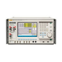
Fluke 6105A User Manual (218 pages)
Electrical Power Standards
Brand:
Fluke
| Category:
Test Equipment
| Size: 1.93 MB
Table of Contents
Table of Contents
3
Introduction
17
Contacting Fluke
17
General Safety Summary
17
Explanation of Safety-Related Symbols and Terms
18
Protective Earth (Grounding)
18
Features
19
About this Manual
19
Specifications
20
General Specifications
20
Input Power
20
Dimensions
20
Environment
20
Safety
20
Emc
20
General Electrical Specifications
21
Amplitude/Frequency Limits
21
Open and Closed Loop Operation
21
Electrical Specifications
22
Voltage Specifications
22
Voltage Channel Maximum Capacitive Loading for Output Stability
22
Voltage Range Limits and Burden
22
Voltage Sine Amplitude Specifications
23
Voltage DC and Harmonic Amplitude Specifications
24
Voltage Distortion and Noise
25
Current Range Limits
25
Load Regulation Specification "Adder
26
Current Sine Amplitude Specifications
26
Current DC and Harmonic Amplitude Specifications
28
Current Distortion and Noise
29
Voltage from the Current Terminals
29
Range Limits and Impedances
29
Sine Specifications
29
DC and Harmonic Amplitude Specifications
30
Voltage from Current Terminals, Distortion and Noise
30
Current to Voltage Phase Specifications
31
Multi-Phase Operation
32
Voltage to Voltage Phase Specifications
32
Energy Specifications
32
Pulse Inputs
32
Pulse and Gate Inputs
32
Pulse Output
32
Gate Output
32
Accuracy
33
Test Duration
33
Power Specifications
33
6105A and 6106A Sinusoidal Power Accuracy at 45 Hz to 65 Hz; Power Factor 1.0 (Ppm)
33
6105A and 6106A Sinusoidal Power Accuracy at 45 Hz to 65 Hz; Power Factor 0.5 (Ppm)
33
6105A and 6106A Sinusoidal Power Accuracy with
34
6100B and 6101B Non-Sinusoidal Power Accuracy with
34
Voltage and Current Sinusoidal and Rectangular Modulation Flicker Specification
35
Fluctuating Harmonic Specifications
35
Interharmonic Specifications
36
Dip/Swell Specifications
36
Determining Non-Sinusoidal Waveform Amplitude Specifications
36
Non-Sinusoidal Voltage Example
37
Apparent Power (S) Accuracy Calculations
37
Apparent Power Example
38
Power (P) Accuracy Calculations
39
Power Example
39
References
41
Installation
43
Chapter 2
45
Introduction
45
Unpack and Inspection
45
To Reship the Instrument
45
Placement
45
Cooling Considerations
45
Line Voltage
46
Connect to Line Power
46
Connect Auxiliary Units
47
Allocation of Phases
48
Connection and Power-Up Sequence
48
Features
49
Chapter 3
51
Introduction
51
Front-Panel Features
51
The Main User Interface Areas
54
Data Entry from the Front Panel
55
Direct/Indirect Mode
56
Using an External Keyboard and Mouse
56
Sample Reference Signal and F10
57
Set up Exercise
57
Switch to the Current Output
58
Enable the Current Channel
58
The Current Channel Is Enabled but Not Operating
59
Set up the L1 Current Channel
59
Over-Compliance Warning Message
60
Turn the Output off
61
Two-Wire / Four-Wire Voltage Settings
61
Four-Wire Sense
62
Two-Wire / Four-Wire Configuration Settings
62
Rear-Panel Features
64
Front-Panel Operation
67
Chapter 4
69
Introduction
69
Power up
69
Warm up
69
Basic Setup Procedures
70
Global Settings
71
Frequency
71
Line Locking
71
Harmonic Edit Mode
71
Reactive Calculations
72
Soft Start
73
Units and Standards
73
Front-Panel Terminals
74
Rear-Panel Output Settings
75
More Settings
76
Voltage from Current Transfer Factors
76
Save Setup and Load Setup Softkeys
76
Set Date and Time
77
GPIB Settings
77
Set Factory Defaults
77
About
77
Edit Mode
77
Direct Mode
77
Deferred Mode
77
Changes that Are Not Deferred
77
Setting up Voltage and Current Waveforms
78
Harmonics, DC and Sine
79
Definition
79
Access to Edit Harmonics
79
6100B Capability
79
Sine/Harmonic Mode
79
Setting up Harmonics and DC
81
Grid Edit Mode
82
Interharmonics
83
Definition
83
Access to Edit Interharmonics
84
6100B Capability
84
Setting up Interharmonics
84
Fluctuating Harmonics
84
Definition
85
Access to Fluctuating Harmonics
85
6100B Capability
85
Setting up Fluctuating Harmonics
85
Dips and Swells
86
Definition
86
Access to Dips and Swells
86
6100B Capability
87
Setting up Dips/Swells
87
Flicker
89
Definition
89
Access to Flicker
89
6100B Capability
90
Setting up Basic Flicker
90
Setting up Flicker Extended Functions
91
Periodic Frequency Changes
92
Distorted Voltage with Multiple Zero Crossings
93
Harmonics with Side Bands
94
Phase Jumps
94
Rectangular Voltage Changes with 20 % Duty Cycle
95
Copy and Paste
96
Copy
96
Paste
96
The Energy Option
96
Overview of Functionality
96
Principle of Operation
96
Limitations
97
Preparing to Use the Energy Option
97
Input Channel Configuration and Meter Constants
99
Connect MUT and Reference Meters
99
Type of Energy
100
Internal Pull-Ups
100
Energy Pulse Output Meter Constant and Pull up
100
Conduct the Test
100
Test Modes
100
Free Run Mode
101
Counted/Timed Mode
101
Gated Mode
102
Packet Mode
103
Remote Operation of the Energy Option
104
Remote Operation
105
Chapter 5
109
Introduction
109
Using the IEEE-488 Port for Remote Control
109
Programming Options
109
Capability Codes
109
Bus Addresses
110
Limited Access
111
Interconnections
111
Operation Via the IEEE 488 Interface
111
General
111
Operating Conditions
111
Programmed Transfer to Local Control (GTL or REN False)
112
Device Clear
112
Levels of Reset
112
Message Exchange
113
IEEE 488.2 Model
113
Instrument STATUS Subsystem
113
Incoming Commands and Queries
114
Instrument Functions and Facilities
114
Outgoing Responses
114
Query Error
114
Request Service (RQS)
115
Reasons for Requesting Service
115
RQS in the IEEE 488.2 Model
115
Retrieval of Device Status Information
115
IEEE 488 and SCPI Standard Defined Features
116
Status Summary Information and SRQ
116
Event Register Conditions
117
Access Via the Application Program
117
Instrument Status Reporting IEEE 488.2 Basics
117
IEEE 488.2 Model
117
Instrument Model Structure
118
Status Byte Register
118
Reading the Status Byte Register
118
Service Request Enable Register
118
Reading the Service Request Enable Register
119
IEEE 488.2 Defined Event Status Register
119
Standard Event Status Enable Register
120
Reading the Standard Event Enable Register
121
The Error Queue
121
Instrument Status Reporting - SCPI Elements
121
General
121
SCPI Status Registers
121
Reportable SCPI States
122
SCPI Programming Language
122
SCPI Commands and Syntax
123
SCPI Command Summary
123
Energy Command Summary
130
Calibration Subsystem Command Details
131
Output Subsystem Command Details
133
Input Subsystem Command Details
135
Source Subsystem Command Details
135
General Commands
135
Power Values
136
Voltage Setup
138
DC and Harmonics Phenomenon
139
Fluctuating Harmonics Phenomenon
141
Interharmonics Phenomenon
142
Dip Phenomenon
142
Flicker Phenomenon
143
Extended Flicker Sub-System
144
Extended Flicker State
145
Configure Signal
145
Select Sideband Harmonic
145
Select Phase Jump Angle
145
Select Phase Jump Settle Period
145
Report Phase Jump Stage
146
Report Phase Jump Elapsed Time
146
Current Setup
146
Harmonics Phenomenon
148
Fluctuating Harmonics Phenomenon
149
Interharmonics Phenomenon
150
Dip Phenomenon
151
Flicker Phenomenon
152
Status Subsystem Command Details
153
System Subsystem Command Details
155
Unit Subsystem Command Details
156
Remote Operation of the Energy Option
157
SCPI Command Set
157
Operating Mode
157
Energy Maintain Voltage
157
Energy Units
158
Result Presentation
158
Results
158
Output Gating
159
Input Gating
159
Warm-Up Sequence Tree
160
Warm-Up Duration
160
Warm-Up Pulse Source
160
Test Sequence Tree
161
Test Duration
161
Test Pulse Source
161
Energy: Abort
162
MUT Tree
162
MUT Meter Constant
162
MUT Meter Constant Units
162
Input Debounce
163
MUT Source
163
MUT Pull-Up
163
Reference Tree
163
Reference Meter Constant
163
Reference Meter Constant Units
163
Reference Source
164
Reference Pull-Up
164
Output Tree
164
Output Meter Constant
164
Output Meter Constant Units
165
Output Pull-Up
165
Common Commands and Queries
165
Clear Status
165
Event Status Enable
165
Recall Event Status Enable
166
Read Event Status Register
166
IDN? (Instrument Identification)
167
Operation Complete
167
Recall the Instrument Hardware Fitment
168
Power-On Status Clear
169
Recall Power on Status Clear Flag
169
Reset
170
Service Request Enable
170
Recall Service Request Enable
171
Read Service Request Register
171
Test Operations - Full Selftest
172
Wait
172
Device Settings after *RST
173
Device Settings at POWER on
174
General
174
Power-On Settings Related to Common IEEE 488.2 Commands
174
RST Settings Related to Common IEEE 488.2 Commands
175
RST Settings Related to SCPI Commands
176
Energy Option Action on Receiving *RST
180
Worked Examples
181
Worked Examples
185
Operator Maintenance
187
Chapter 6
189
Introduction
189
Confidence Test
189
Setting up and Running the Confidence Test
189
Changing the User Password
190
Accessing the Fuse
190
How to Clean the Instrument
191
How to Clean the Air Filter
191
Lithium Battery Replacement
193
Calibration
195
Chapter 7
197
Introduction
197
Calibration Methods
197
Full Calibration Verification and Adjustment
197
Confidence Check
197
Partial Adjustment
197
Confidence Check of a Poly-Phase System
197
Best Calibration Accuracy
198
Amplitude Measurements
198
Phase Measurement
198
The Effect of Phase Uncertainty on Power Accuracy
199
Calibration Uncertainties for Full Accuracy
200
Required Equipment
200
Overview of 6100B Signal Generation
201
Independence of 6100B and 6101B
201
The Fluke Service Center Calibration System
203
Characteristics of the Calibration System
206
Transducers
206
DMM Amplitude Error Contributions
206
DMM Amplitude Phase Contributions
207
Voltage to Voltage Phase Uncertainty
207
Current to Voltage Phase Uncertainty
207
Overview of Adjustment
207
Calibration Adjustment Process
208
Entering Calibration Mode
208
Select Instrument Configuration
208
Determine the 6100B Error
209
Initiate the Adjustment
209
Return Calibration Switch to Normal
209
Verification
210
Calibration Adjustment Points
210
Energy Option Calibration
213
Using Direct Measurement with a Frequency Meter
213
Using an External Reference Frequency
214
Advertisement
Fluke 6105A Manual (56 pages)
Brand:
Fluke
| Category:
Test Equipment
| Size: 5.03 MB
Table of Contents
Table of Contents
2
Electrical Calibration
4
DC/LF Electrical Calibrators
7
Specialty Calibrators
8
Oscilloscope Calibrators
9
Precision Multimeters
9
Electrical Standards
10
RF References
12
Temperature Calibration
13
Standard Platinum Resistance Thermometers
20
Fixed-Point Cells
20
Cell Maintenance Apparatus
21
Thermometer Readouts
22
Reference Prts
23
Thermocouples
23
Thermistors
23
Compact Calibration Baths
24
Standard Calibration Baths
24
Special Application Baths
25
Bath Controllers
25
Metrology Wells
25
Field Metrology Wells
25
Dual-Block Dry-Well
26
Field Dry-Well Calibrators
26
Micro-Baths
26
Portable Calbration Baths
26
Handheld Calibrators
26
Infrared Calibrators
27
Zero-Point Dry-Well
27
Surface Probe Calibrator
27
Thermocouple Furnaces
27
Humidity Calibration
28
Humidity Calibrators
29
Pressure Calibration
30
Gas Pressure Controllers/Calibrators
34
Series Piston Gauges
34
High Pressure Controllers/Calibrators
35
Reference Pressure Indicators
35
2400 Series Piston Gauges
36
Specialty Piston Gauges
37
Manual Pressure Generation and Control
37
Industrial Deadweight Testers
38
Pressure Comparators
38
Pressure Calibrators
39
Air Data Calibration
40
Pressure Calibration Systems
40
Gas Flow Calibration
41
Gas Flow Standards
42
Calibration Software
43
Electrical and RF Calibration Software
45
Calibration Asset Management Software
45
Software Support Programs
45
Temperature Calibration Software
46
Pressure/Flow Calibration Software
47
Data Acquisition
48
2638A Hydra Series III Data Acquisition System
49
Fluke DAQ 6.0 Application Software
49
Service Programs
52
Training
53
Fluke 6105A Getting Started (34 pages)
Electrical Power Quality
Brand:
Fluke
| Category:
Test Equipment
| Size: 0.63 MB
Table of Contents
Table of Contents
3
Introduction
9
Contacting Fluke
10
General Safety Summary
10
Explanation of Safety-Related Symbols and Terms
11
Protective Earth (Grounding)
11
Power Cord and Power Supply Disconnection
11
Signal Connection
12
Safe Operating Conditions
12
Fuse Requirements
13
Measurement Category I
13
Maintenance and Repair
13
Cleaning
13
Ventilation and Dust
13
Features
14
General Specifications
14
Input Power
14
Dimensions
14
Environment
15
Safety
15
Emc
15
Unpacking and Inspection
15
Reshipping the Instrument
15
Placement and Rack Mounting
15
Cooling Considerations
16
Line Voltage
16
Connecting to Line Power
16
Connecting Auxiliary Units
17
Allocation of Phases
18
Connection and Power-Up Sequence
18
Front-Panel Features
19
The Main User Interface Areas
22
Data Entry from the Front Panel
23
Direct/Indirect Mode
24
Using an External Keyboard and Mouse
24
Sample Reference Signal and F10
25
6100B Set up Exercise
25
Switch to the Current Output
26
Enable the Current Channel
26
The Current Channel Is Enabled but Not Operating
27
Set up the L1 Current Channel
27
Over Compliance Warning Message
28
Complete the Current Circuit and Turn the Output on
29
Turn the Output off
29
Two-Wire / Four-Wire Voltage Settings
29
Four-Wire Sense
30
Two-Wire / Four-Wire Configuration Settings
30
Rear-Panel Features
32
Advertisement
Advertisement
Related Products
Fluke 6100B
Fluke 6109A
Fluke 6135A/PMU
Fluke 6101B
Fluke 6106A
Fluke 6135A/PMUCAL
Fluke 685
Fluke 683
Fluke 682
Fluke 680
Fluke Categories
Measuring Instruments
Test Equipment
Multimeter
Thermometer
Laboratory Equipment
More Fluke Manuals
Login
Sign In
OR
Sign in with Facebook
Sign in with Google
Upload manual
Upload from disk
Upload from URL