Table of Contents
Advertisement
Quick Links
Advertisement
Table of Contents

Related Manuals for Shinko JCM-33A


Summary of Contents for Shinko JCM-33A
- Page 1 MICRO-COMPUTER BASED DIGITAL INDICATING CONTROLLER JCM-33A INSTRUCTION MANUAL...
- Page 2 • Any unauthorized transfer or copying of this document, in part or in whole, is prohibited. • Shinko Technos CO., LTD. is not liable for any damages or secondary damages incurred as a result of using this product, including any indirect damages.
- Page 3 Caution • Use the solderless terminal with an insulation sleeve that fits in the M3 screw when wiring the JCM-33A Series. • The terminal block of this instrument is designed to be wired from the left side. The lead wire must be inserted from the left side of the terminal, and fastened with the terminal screw.
-
Page 4: Table Of Contents
--- CONTENTS --- 1. Model name 1.1 Explanation of model name ------------------------------------------------------· 6 1.2 Rated input ---------------------------------------------------------------------------· 7 1.3 How to read the model nameplate --------------------------------------------- · 7 2. Name and functions of the sections ------------------------------------ 8 3. Mounting to control panel 3.1 Site selection ----------------------------------------------------------------------- 10 3.2 External dimension ---------------------------------------------------------------- 10 3.3 Panel cutout ------------------------------------------------------------------------- 10... - Page 5 OUT1 low limit setting ------------------------------------------------------------ · 22 OUT1 ON/OFF action hysteresis setting ------------------------------------ · 22 OUT2 action mode selection ---------------------------------------------------- 23 OUT2 high limit setting ----------------------------------------------------------- 23 OUT2 low limit setting ------------------------------------------------------------ 23 Overlap band/Dead band setting ----------------------------------------------- 23 OUT2 ON/OFF action hysteresis setting ------------------------------------- 23 A1 action selection ----------------------------------------------------------------- 23 A2 action selection ----------------------------------------------------------------- 24 A1 action Energized/Deenergized selection -------------------------------- 24...
-
Page 6: Model Name
1. Model name 1.1 Explanation of model name The series name, control output (OUT1), input and option codes are entered where underlined. e.g.) J C M – 3 3 A – R / M Alarm 2 (A2) output Multi-range input Relay contact output 72 x 72 x 100mm Standard specification... -
Page 7: Rated Input
Model nameplates are attached to the case and the inner assembly. When the supply voltage is 24V AC/DC, “1” is entered before the option code. Model nameplate (e.g.) JCM-33A-R/M Relay contact output/Multi-range input Alarm 2 (A2) output W (20A) Heater burnout alarm output (20A) -
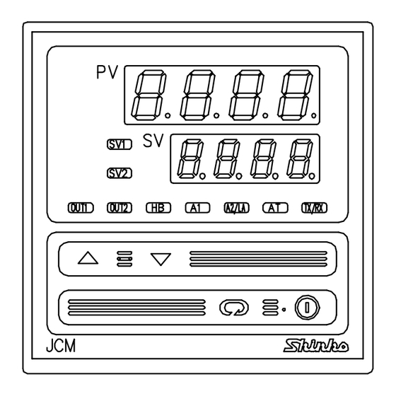
Page 8: Name And Functions Of The Sections
2. Name and functions of the sections (10) (11) (12) (13) (14) (15) (Fig. 2-1) (1) PV display Indicates the Process variable (PV) with a red LED. (2) SV display Indicates the Setting value (SV) or Manipulated variable (MV) with a green LED. (3) SV1 indicator Lights up with a green LED when SV1 is selected. - Page 9 (10) AT indicator A yellow LED blinks during auto-tuning or auto-reset. (11) TX/RX indicator A yellow LED lights during serial communication TX output (transmission). (12) Increase key ( ): Increases the numeric value. (13) Decrease key ( ): Decreases the numeric value. (14) Mode key ( ): Selects the setting mode or registers the setting value.
-
Page 10: Mounting To Control Panel
3. Mounting to control panel 3.1 Site selection This instrument is intended to be used under the following environmental conditions (IEC61010-1): Overvoltage category , Pollution degree 2 Mount the controller in a place with: A minimum of dust, and an absence of corrosive gases (2) No flammable, explosive gasses (3) No mechanical vibrations or shocks (4) No exposure to direct sunlight, an ambient temperature of 0 to 50... -
Page 11: Ct (Current Transformer) External Dimension
3.4 CT (Current transformer) external dimension CTL-6-S (for 5A, 10A and 20A) CTL-12-S36-10L1 (for 50A) (Fig. 3.4-1) 3.5 Mounting Notice As the case is made of resin, do not use excessive force while screwing in the mounting bracket, or the case or screw type mounting bracket could be damaged. The torque is approximately 0.12N•m. -
Page 12: Wiring Connection
4. Wiring connection Warning Turn the power supply to the instrument off before wiring or checking. Working or touching the terminal with the power switched on may result in severe injury or death due to Electric Shock. Moreover, the instrument must be grounded before the power supply to the instrument is turned on. -
Page 13: Wiring Connection Examples
Notice • The terminal block of JCM-33A series is designed to be wired from the left side. The lead wire must be inserted from the left side of the terminal, and fastened with the terminal screw. • Dotted lines show options, and if the option is not designated, its terminals are not mounted. - Page 14 CT. (3) When wiring, keep CT wire away from any AC source and load wire to avoid external interference. Heater (Fig. 4.2-1) [JCM-33A-S/E] Single phase Alarm unit Heater Thermocouple Electric furnace (Fig. 4.2-2) •...
-
Page 15: Setup
5. Setup For the thermocouple and RTD input, the sensor input character and temperature unit are indicated on the PV display and the input range high limit value is indicated on the SV display for approx. 3 seconds after the power is turned on. See (Table 5-1). For DC input, the sensor input character is indicated on the PV display and the scaling high limit value is indicated on the SV display. -
Page 16: Setup Flowchart
5.1 Setup flowchart Control output OFF function Output manipulated PV/SV display mode variable indication ( Approx. ] (*1) (Approx. 3s) (Approx. 3s) (Approx. 3s) [Main setting mode] [Sub setting mode] [Auxiliary function [Auxiliary function setting mode 1] setting mode 2] AT setting/Auto-reset Setting value lock Input type selection... -
Page 17: Main Setting Mode
5.2 Main setting mode The main setting mode can be selected by pressing the key. The setting value can be increased or decreased by pressing the key. The setting value is registered by pressing the key, and the mode reverts to the PV/SV display mode. -
Page 18: Out1 Proportional Band Setting
OUT1 proportional band setting [ ] • Sets OUT1 proportional band. The control action becomes ON/OFF action when set to 0 or 0.0. • Setting range: 0 to 1000 (0 to 2000 ) With a decimal point, 0.0 to 999.9 (0.0 to 999.9 ) With DC input, 0.0 to 100.0% •... -
Page 19: A2 Setting
A2 setting [ • Sets the action point for A2 output. Setting the value to 0 or 0.0 disables the function. (excluding Process high and low alarms) • Not available when A2 (option) is not added or when No alarm action is selected in A2 action selection. -
Page 20: Auxiliary Function Setting Mode
• Selecting item: (Shinko protocol), (Modbus ASCII mode) (Modbus RTU mode) • Default value: Shinko protocol Instrument number setting [ • Sets the instrument number. (Communication cannot be carried out unless an instrument number is individually set when communicating by connecting plural instruments in serial communication.) -
Page 21: Data Transfer Rate Selection
(19200bps) • Default value: 9600bps Parity selection [ • Selects the parity. • Not available when Serial communication (option) is not added or when Shinko protocol is selected in the Communication protocol selection. • Selecting item: (No parity), (Even parity), (Odd parity) •... -
Page 22: Scaling High Limit Setting
–199.9 to 500.0 –199.9 to 900.0 JPt100 –200 to 500 –300 to 900 4 to 20mA DC –1999 to 9999: 0 to 20mA DC –1999 to 9999: 0 to 1V DC –1999 to 9999: 0 to 5V DC –1999 to 9999: 1 to 5V DC –1999 to 9999: 0 to 10V DC... -
Page 23: Out2 Action Mode Selection
OUT2 action mode selection [ • Selects a cooling action from Air cooling, Oil cooling and Water cooling. Not available when OUT2 is ON/OFF action or when the option Heating/Cooling control is not applied • : Air cooling (Linear characteristic) : Oil cooling (The 1.5th power of the linear characteristic) : Water cooling (The 2nd power of the linear characteristic) •... -
Page 24: A2 Action Selection
A2 action selection [ • Selects A2 action. • Available only when the option A2 is applied • The selecting item and default value are the same as those of A1 action selection. A1 action Energized/Deenergized selection [ • Selects A1 action Energized/Deenergized. •... -
Page 25: At Bias Setting
AT bias setting [ • Sets the bias value when PID auto-tuning is performing. • Not available for DC input • Setting range: 0 to 50 (0 to 100 ) With a decimal point,0.0 to 50.0 (0.0 to 100.0 ) •... -
Page 26: Control Output Off Function
Energized/Deenergized function [If the alarm action Energized is selected] When the alarm output indicator is lit, the alarm output (terminals 15-16 or 17-18) is conducted (ON). When the alarm output indicator is unlit, the alarm output is not conducted (OFF). See (Fig. 5.5-1). [If the alarm action Deenergized is selected] When the alarm output indicator is lit, the alarm output (terminals 15-16 or 17-18) is not conducted (OFF). -
Page 27: Running
After the controller has been mounted to the control panel and wiring is completed, it can be started in the following manner. (1) Turn the power supply to the JCM-33A Series ON. With thermocouple and RTD input, sensor input character and temperature unit are indicated on the PV display and the input range high limit value is indicated on the SV display for approx. -
Page 28: Action Explanation
7. Action explanation 7.1 OUT1 action Heating (reverse) action Cooling (direct) action Proportional band Proportional band Control action SV setting SV setting Relay contact output Cycle action is performed according to deviation. Cycle action is performed according to deviation. Non-contact 12V DC 12/0V DC 0V DC... -
Page 29: Out1 On/Off Action
7.3 OUT1 ON/OFF action Heating (reverse) action Cooling (direct) action Hysteresis Hysteresis Control action SV setting SV setting Relay contact output Non-contact 12V DC 0V DC 0V DC 12V DC voltage output DC current 20mA DC 20mA DC 4mA DC 4mA DC output Indication... -
Page 30: Out2 (Heating/Cooling Control) Action (Option)
7.4 OUT2 (Heating/Cooling control) action (Option) Heating P-band (Cooling P-band) Control Heaing (Cooling action action action) SV setting Relay contact output (OUT1) Cycle action is performed according to deviation. Relay contact output (OUT2) Cycle action is performed according to deviation. Non-contact 12V DC 12/0V DC... - Page 31 When setting Dead band Heating P-band Dead band (Cooling P-band) Heatng (Cooling Control action action action) SV setting Relay contact output (OUT1) Cycle action is performed according to deviation. Relay contact output (OUT2) Cycle action is performed according to deviation. Non-contact 12V DC 12/0V DC...
- Page 32 When setting Overlap band Heating P-band Cooling P-band Overlap band Control action Heating (Cooling action action) SV setting Relay contact output (OUT1) Cycle action is performed according to deviation. Relay contact output (OUT2) Cycle action is performed according to deviation. Non-contact voltage output 12V DC...
-
Page 33: A1 And A2 Actions
7.5 A1 and A2 actions High limit alarm Low limit alarm A1 hysteresis A1 hysteresis Alarm action + A1 + A1 set point set point set point setting set point setting + side + side Alarm output side side High/Low limits alarm High/Low limit range alarm A1 hysteresis A1 hysteresis... -
Page 34: Sv1/Sv2 External Selection Action
High/Low limits alarm with standby A1 hysteresis Alarm action SV setting set point set point Alarm output : A1 output terminals 15 and 16 are connected (ON). A1 output terminals 15 and 16 are connected (ON) or disconnected (OFF). : A1 output terminals 15 and 16 are disconnected (OFF). : Standby functions. -
Page 35: Control Action Explanations
8. Control action explanations 8.1 PID (1) Proportional band (P) Proportional action is the action which the control output varies in proportion to the deviation between the setting value and the processing temperature. If the proportional band is narrowed, even if the output changes by a slight variation of the processing temperature, better control results can be obtained as the offset decreases. -
Page 36: Auto-Reset (Offset Correction)
(2) When the control is stable or when control temperature is within ( ) of setting value. Fluctuation is applied at the setting value. (1) Calculating PID constant Setting value (2) PID constant calculated Temperature (3) Controlled by the PID constant set by auto-tuning. -
Page 37: Specifications
250V AC (inductive load cosø=0.4) Electrical life, 100,000 times Non-contact voltage: 12 V DC maximum 40mA (short circuit protected) The connectable SSRs in parallel are 4 units if Shinko SSRs (SA-200 series) are used. DC current : 4 to 20mA DC... - Page 38 A1 output When A1 action is set as energized, the alarm action point is set by deviation to the main setting (except Process alarm). When the input goes outside the range, the output turns ON or OFF (in the case of High/Low limit range alarm).
-
Page 39: Dielectric Strength
Circuit isolation configuration Isolation Ground OUT2, HB (W) or Isolated power output output (P24) Power source Input OUT1 Input • When OUT1 is non-contact voltage or DC current output type and when OUT2 is Non-contact voltage or DC current output type, A to B is non-isolated. •... - Page 40 Input Input range Indication range Control range –199.9 to 400.0 –199.9 to 450.0 –205.0 to 450.0 K,T –199.9 to 750.0 –199.9 to 850.0 –209.0 to 850.0 –200 to 1370 –250 to 1420 –250 to 1420 –320 to 2500 –370 to 2550 –370 to 2550 –200 to 1000 –250 to 1050...
-
Page 41: Optional Specifications
[Burnout] When the thermocouple or RTD input is burnt out, OUT1 is turned off (for DC current output type, OUT1 low limit value) and the PV display blinks “ ”. [Self-diagnosis] The CPU is monitored by a watchdog timer, and when any abnormal status is found on the CPU, the controller is switched to warm-up status. - Page 42 Setting accuracy : The same as the Indicating accuracy Action : ON/OFF action Hysteresis : For thermocouple and RTD input, 0.1 to 100.0 For DC current and voltage input, 1 to 1000 (The placement of the decimal point follows the selection) Output : Relay contact 1a Control capacity, 3A...
-
Page 43: Option Combination
SVTC). [Setting value Lock of the JCM-33A must be set to Lock 3.] When SV data from Shinko programmable controller is greater than SV high limit or smaller than SV low limit, JCM-33A ignores the value and controls with the SV high limit or SV low limit. -
Page 44: Troubleshooting
10. Troubleshooting If any malfunctions occur, refer to the following items after checking the power of the controller. Warning Turn the power supply to the instrument off before wiring or checking. Working or touching the terminal with the power switched on may result in severe injury or death due to Electric Shock. - Page 45 • Is the input terminal of DC voltage (1 to 5V DC) and ] is blinking DC current (4 to 20mA DC) securely connected to the on the PV display. input terminal of this controller? Connect the sensor terminal to the controller terminal securely.
-
Page 46: Character Table
The setting indication • SV high limit or low limit may be set at the point the value does not change. does not change within the rated input even if Set it again in Auxiliary function setting mode 1. keys are pressed, and settings are impossible. - Page 47 Input range high limit value SV low limit setting Input range low limit value Sensor correction setting Communication protocol selection Shinko protocol Instrument number setting Communication speed selection 9600bps Parity selection Even Stop bit selection [Auxiliary function setting mode 2]...
- Page 48 For any inquiries about this unit, please contact our agency or the shop where you purchased the unit after checking the following. [Example] • Model --------------------------- JCM-33A-R/M • Input type ------------------------ K • Option --------------------------- A2, C5 • Instrument number ---------- No.
Need help?
Do you have a question about the JCM-33A and is the answer not in the manual?
Questions and answers