Table of Contents
Advertisement
Available languages
Available languages
GRIGLIA CERAMICA GAS
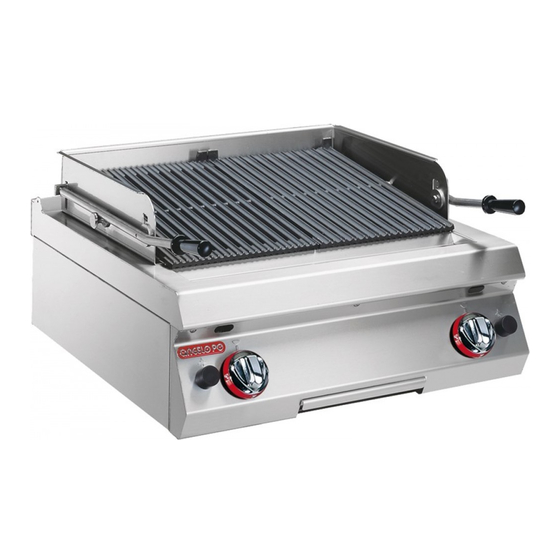
GAS CHARGRILL
1G0GRG
GAS-BRATPLATTE MIT KERAMIKEINSÄTZEN
GRILLADE GAZ À PIERRES CÉRAMIQUES
PARRILLA GAS EN PIEDRA CERÁMICA
MANUALE D'USO E INSTALLAZIONE
USE AND INSTALLATION MANUAL
BEDIEN- UND INSTALLATIONSHANDBUCH
MANUEL D'UTILISATION ET D'INSTALLATION
MANUAL DE USO E INSTALACIÓN
IT
Italiano
GB
English
DE
Deutsch
FR
Français
ES
Español
Ed. 2
09/2011
3142940
Advertisement
Chapters
Table of Contents

Related Manuals for Angelo Po 1G0GRG


Summary of Contents for Angelo Po 1G0GRG
- Page 1 GRIGLIA CERAMICA GAS GAS CHARGRILL 1G0GRG GAS-BRATPLATTE MIT KERAMIKEINSÄTZEN GRILLADE GAZ À PIERRES CÉRAMIQUES PARRILLA GAS EN PIEDRA CERÁMICA MANUALE D’USO E INSTALLAZIONE USE AND INSTALLATION MANUAL BEDIEN- UND INSTALLATIONSHANDBUCH MANUEL D’UTILISATION ET D’INSTALLATION MANUAL DE USO E INSTALACIÓN Italiano...
-
Page 3: Table Of Contents
INDICE rif. capitoli pag. 1 INFORMAZIONI GENERALI ..........2 2 INFORMAZIONI TECNICHE ..........4 3 SICUREZZA............... 6 PARTE 4 USO E FUNZIONAMENTO ..........7 5 MANUTENZIONI ..............9 6 GUASTI ................12 7 MOVIMENTAZIONE E INSTALLAZIONE ......13 8 REGOLAZIONI ..............17 9 SOSTITUZIONE PARTI ........... -
Page 4: Informazioni Generali
INFORMAZIONI GENERALI RACCOMANDAZIONI PER IL LETTORE Per rintracciare facilmente gli argomenti specifici di parte: contiene tutte le informazioni ne- interesse, consultare l’indice analitico posto all’ini- cessarie ai destinatari omogenei, cioè tutti gli zio del manuale. operatori esperti e autorizzati a movimentare, Questo manuale è... - Page 5 IDENTIFICAZIONE COSTRUTTORE E APPARECCHIATURA La targhetta di identificazione raffigurata, è applica- ) Tipo di gas ta direttamente sull'apparecchiatura. In essa sono ) Potenza dichiarata (kW) riportati i riferimenti e tutte le indicazioni indispensa- ) Consumo gas bili alla sicurezza di esercizio. ) Indicatore gas collaudo Targa complementare ) Data di costruzione...
-
Page 6: Informazioni Tecniche
INFORMAZIONI TECNICHE DESCRIZIONE GENERALE APPARECCHIATURA La griglia ceramica, d'ora innanzi definita apparec- chiatura, è stata progettata e costruita per la cottura dei cibi a diretto contatto con la griglia, nell'ambito della ristorazione professionale. Organi principali A)Griglia di cottura: è realizzata in ghisa. B)Telaio paraspruzzi: per riparare dagli spruzzi provocati dalla cottura C)Griglia focolaio: per sostenere le mattonelle. - Page 7 SEGNALI DI SICUREZZA E INFORMAZIONE L'illustrazione indica la posizione dei segnali appli- cati. A)Targa identificazione costruttore e apparec- chiatura. B)Pericolo di scottatura: fare attenzione alle su- perfici calde. C)Pericolo generico: durante il lavaggio dell'appa- recchiatura non dirigere getti d'acqua in pressio- ne sulle parti interne.
-
Page 8: Sicurezza
SICUREZZA AVVERTENZE GENERALI DI SICUREZZA – Il costruttore, in fase di progettazione e costruzio- capacità devono essere eseguiti esclusivamente ne, ha posto particolare attenzione agli aspetti da personale qualificato, con esperienza ricono- che possono provocare rischi alla sicurezza e sciuta e acquisita nel settore specifico di inter- alla salute delle persone che interagiscono con vento. -
Page 9: Uso E Funzionamento
AVVERTENZE DI SICUREZZA PER L'EQUIPAGGIAMENTO ELETTRICO L'equipaggiamento elettrico è stato progettato e co- contenere agenti contaminanti e corrosivi (acidi, struito secondo quanto previsto dalle norme vigenti sostanze chimiche, sali, ecc.) e non devono poter penetrare e/o venire in contatto con i componenti in materia. - Page 10 DESCRIZIONE COMANDI Sull'apparecchiatura sono disposti i comandi per at- B)Pulsante accensione piezoelettrica: serve per tivare le funzioni principali. accendere la spia pilota dei bruciatori. A)Manopola comando bruciatore: per accende- re, spegnere e regolare il relativo bruciatore e spia pilota. Índice apagado Índice testigo piloto Índice encendido piezoeléctrico Índice potencia máxima...
-
Page 11: Manutenzioni
INATTIVITÀ PROLUNGATA DELL’APPARECCHIATURA Se l'apparecchiatura rimane inattiva per un lungo 4 - Eseguire tutte le operazioni di manutenzione. tempo, procedere nel modo indicato. 5 - Ricoprire l'apparecchiatura con un involucro e lasciare alcune fessure per la circolazione 1 - Chiudere il rubinetto alimentazione gas. 2 - Pulire accuratamente l'apparecchiatura e le dell'aria. - Page 12 PULIZIA APPARECCHIATURA Se si considera che l'apparecchiatura è utilizzata 3 - Pulire gli accessori dopo l'uso, con uno sgras- per la preparazione di prodotti alimentari per l'uo- sante idoneo. Si consiglia il lavaggio in lavasto- viglie. mo, è necessario prestare particolare cura a tutto ciò...
- Page 13 6 - Smontare il telaio paraspruzzi (C) e pulirlo. 7 - Sollevare e capovolgere la griglia focolaio (D). Effettuare questa operazione giornalmente, per consentire la pulizia delle mattonelle da even- tuali incrostazioni tramite le fiamme dei brucia- tori. 8 - Togliere la bacinella di raccolta (E), svuotarla e pulirla.
-
Page 14: Guasti
CONTROLLO PRESSIONE GAS Per questa operazione proce- dere nel modo indicato. 1 - Chiudere il rubinetto ali- mentazione gas. 2 - Sfilare le manopole (A). 3 - Svitare le viti (B) e smon- tare il cruscotto (C). 4 - Svitare la vite (D) della presa di pressione. -
Page 15: Movimentazione E Installazione
MOVIMENTAZIONE E INSTALLAZIONE RACCOMANDAZIONI PER LA MOVIMENTAZIONE E INSTALLAZIONE Importante Eseguire la movimentazione e l'installazio- ste operazioni dovrà, se necessario, orga- ne nel rispetto delle informazioni fornite dal nizzare “piano sicurezza” costruttore e riportate direttamente sull'im- salvaguardare l'incolumità delle persone ballo, sull'apparecchiatura e nelle istruzioni direttamente coinvolte. - Page 16 MOVIMENTAZIONE E SOLLEVAMENTO L'apparecchiatura può essere movimentata con un dispositivo di sollevamento a forche o a gancio di portata adeguata. Prima di effettuare questa opera- zione, controllare la posizione del baricentro del ca- rico. Importante Nell'inserire il dispositivo di sollevamento, fare attenzione al tubo di alimentazione gas.
- Page 17 MONTAGGIO APPARECCHIATURE IN BATTERIA Per montare le apparecchiature in batteria (fianco a fianco) procedere nel modo indicato. 1 - Sfilare le manopole (A). 2 - Svitare le viti (B) e smontare i cruscotti (C). 3 - Applicare, sui bordi da accostare, del nastro adesivo di protezione.
- Page 18 ALLACCIAMENTO GAS Importante Chi è autorizzato ad effettuare tale opera- zione deve possedere capacità ed espe- rienza acquisita e riconosciuta nel settore specifico, dovrà eseguire l'allacciamento a regola d'arte e tenere conto di tutti i requisi- ti normativi e legislativi. Ad allacciamento completato, prima di rendere operativa l'at- trezzatura, si dovrà...
-
Page 19: Regolazioni
COLLAUDO APPARECCHIATURA 3 - Verificare la regolare accensione e combustione Importante del bruciatore. Prima della messa in servizio, deve essere 4 - Verificare il corretto funzionamento della termo- coppia di sicurezza. eseguito il collaudo dell'impianto, al fine di 5 - Verificare che non vi siano perdite di gas. valutare le condizioni operative di ogni sin- 6 - Verificare che le targhette siano compilate con le golo componente ed individuare le eventuali... - Page 20 Metano Procedere nel modo indica- 1 - Chiudere il rubinetto ali- mentazione gas. 2 - Sfilare le manopole (A). 3 - Svitare le viti (B) e smontare cruscotto (C). 4 - Svitare la vite (D) della presa di pressione. 5 - Collegare il manometro (E) alla presa di pressio- IDM-39606100900.tif ne (F).
-
Page 21: Sostituzione Parti
SOSTITUZIONE PARTI RACCOMANDAZIONI PER LA SOSTITUZIONE PARTI Prima di effettuare qualsiasi intervento di sostituzio- danni alla sicurezza e alla salute delle persone. Qua- ne, attivare tutti i dispositivi di sicurezza previsti e va- lora sia necessario sostituire dei componenti usurati, lutare se sia necessario informare adeguatamente il utilizzare esclusivamente dei ricambi originali. - Page 22 SOSTITUZIONE UGELLO SPIA PILOTA Per questa operazione procedere nel modo indica- 1 - Chiudere il rubinetto alimentazione gas. 2 - Accedere alla spia pilota attraverso l'apertura situata sotto l'apparecchiatura. 3 - Svitare il raccordo (A). 4 - Estrarre l'ugello (B) e sostituirlo con quello adatto al tipo di gas utilizzato (vedi tabella in fondo al manuale).
- Page 23 CONTENTS ref. chapters page 1 GENERAL INFORMATION ..........2 2 TECHNICAL INFORMATION..........4 3 SAFETY ................6 PART 4 USE AND OPERATION ............. 7 5 SERVICING ............... 9 6 FAULT ................12 7 HANDLING AND INSTALLATION ........13 8 ADJUSTMENTS............... 17 9 REPLACING PARTS ............
-
Page 24: General Information
GENERAL INFORMATION INFORMATION FOR THE READER To find the specific topics of interest to you quickly, part: contains all the information neces- refer to the index at the start of the manual. sary for special categories of reader, i.e. all This manual is subdivided into two parts. - Page 25 IDENTIFICATION OF CONSTRUCTOR AND APPLIANCE The nameplate shown here is fitted directly to the ) Rated power (kW) ) Gas consumption appliance. It contains references and all essential ) Testing gas indicator frame information for operating safety. ) Date of construction Extra nameplate Testing gas plate ) Country of use...
-
Page 26: Technical Information
TECHNICAL INFORMATION GENERAL DESCRIPTION OF APPLIANCE The gas chargrill, referred to from now on as the ap- pliance, is designed and produced for cooking foods in direct contact with the griddle in the profes- sional catering sector. Main Parts A)Cooking plate: in cast iron. B)Splashguard frame: shields against splashes when cooking. - Page 27 SAFETY AND INFORMATION SIGNS The illustration shows the position of the signs pro- vided. A)Nameplate with manufacturer and appliance data. B)Burn hazard: watch out for hot surfaces. C)General hazard: when washing the appliance do not point pressurised water jets at internal parts. D)General hazard: read the manual carefully be- fore carrying out any procedure.
-
Page 28: Safety
SAFETY GENERAL SAFETY PRECAUTIONS – During design and construction, the constructor the specific sector. has paid special attention to factors which may – Clean all parts which may come into direct or in- cause risks to the health and safety of the people direct contact with foods, and all the surrounding interacting with the appliance. -
Page 29: Use And Operation
SAFETY WARNINGS FOR ELECTRICAL EQUIPMENT The electrical equipment has been designed and tion and maintenance must not contain contami- constructed in accordance with the relevant regula- nants or corrosives (acids, chemicals, salts, etc.) and must not be able to penetrate and/or come tions. - Page 30 DESCRIPTION OF CONTROLS The appliance is fitted with the controls for use of its B)Piezoelectric ignition button; lights the burner main functions. pilot light. A)Burner control knob: for lighting, turning off and regulating the relative burner and pilot light Off marker Pilot light marker Piezoelectric ignition marker Full power marker...
-
Page 31: Servicing
LENGTHY DOWNTIMES OF APPLIANCE If the appliance is to be out of use for a lengthy pe- 3 - Spread a film of edible oil over the stainless riod, proceed as follows. steel surfaces. 1 - Turn off the gas supply tap. 4 - Carry out all the servicing procedures. - Page 32 CLEANING INSTRUCTIONS Since the appliance is used for preparing foods for Caution - warning human consumption, special care must be paid to Never use products containing substances everything relating to hygiene, and the appliance harmful or hazardous for health (solvents, pe- and the entire surrounding environment must con- troleum spirits, etc.).
- Page 33 6 - Remove the splash guard frame (C) and clean 7 - Lift and turn over the grid clearance reduction (D). Do this every day to allow residue to be burnt off the ceramic bricks. 8 - Remove the drip tray (E), drain it and clean it. Important Do not dump the contents of the drip tray in the environment;...
-
Page 34: Fault
CHECKING GAS PRESSURE To carry out this operation, proceed as follows. 1 - Turn off the gas supply tap. 2 - Pull off the knob (A). 3 - Undo the screws (B) and remove the control panel (C). 4 - Undo the screw (D) of the pressure connection. -
Page 35: Handling And Installation
HANDLING AND INSTALLATION RECOMMENDATIONS FOR HANDLING AND INSTALLATION Important When handling and installing the appliance use. If necessary, the person authorised to comply with the information provided by carry out these operations must organise a the constructor directly on the packaging, "safety plan"... - Page 36 HANDLING AND LIFTING The appliance can be handled using fork-lift or hook equipment of suitable load-carrying capacity. Be- fore lifting, check the position of the load's centre of gravity. Important When engaging with the lifting equipment, watch out for the gas supply pipe. IDM-39606100700.tif INSTALLATION OF THE APPLIANCE All installation stages must be considered right from...
- Page 37 ASSEMBLY APPLIANCES IN BANKS To assemble appliances in banks (side by side) proceed as described below. 1 - Pull off the knob (A). 2 - Undo the screws (B) and remove the control panels (C). 3 - Apply masking tape to the edges to be placed side by side.
- Page 38 GAS CONNECTION Important Those authorised to carry out this opera- tion must have experience acquired and certified in the specific sector, must make the connection to the proper standards, and must comply with all the relevant regu- lations and legislation. Once the connec- tion has been made, before the appliance is put into operation a general check must be made to ensure there are no gas leaks.
-
Page 39: Adjustments
TESTING OF THE APPLIANCE 3 - Check that the burner is switching on correctly Important and its combustion. Before it is put into service, the system 4 - Check that the safety thermocouple is working correctly. must be tested to check the operating con- 5 - Check that there are no gas leaks. - Page 40 Natural gas Proceed as follows. 1 - Turn off the gas supply tap. 2 - Pull off the knob (A). 3 - Undo the screws (B) and remove the control panel (C). 4 - Undo the screw (D) of the pressure connection. 5 - Connect the pressure gauge (E) to the pres- sure test point (F).
-
Page 41: Replacing Parts
REPLACING PARTS RECOMMENDATIONS FOR REPLACING PARTS Before carrying out any replacement procedure, ac- use original spare parts only. The manufacturer de- tivate all the safety devices provided and decide clines all responsibly for injury or damage to com- whether staff at work and those in the vicinity ponents due to the use of non original parts, or should be informed. - Page 42 REPLACEMENT OF THE PILOT LIGHT INJECTOR To carry out this operation, proceed as follows. 1 - Turn off the gas supply tap. 2 - Access the pilot light through the opening pro- vided in the bottom of the appliance. 3 - Unscrew the union (A). 4 - Remove the nozzle (B) and replace it with the one suitable for the type of gas in use (see table at back of manual).
- Page 43 INHALTSVERZEICHNIS Ref. Kapitel Seite 1 ALLGEMEINES..............2 2 TECHNISCHE INFORMATIONEN........4 3 SICHERHEIT ..............6 1. TEIL 4 GEBRAUCH UND BETRIEB..........7 5 WARTUNG................. 9 6 DEFEKTE................. 12 7 HANDHABUNG UND INSTALLATION ......13 8 EINSTELLUNGEN ............17 9 AUSTAUSCH VON BAUTEILE ........19 2.
-
Page 44: Allgemeines
ALLGEMEINES INFORMATIONEN FÜR DEN LESER Konsultieren Sie das Sachregister, das am Anfang 2. Teil: Diese Informationen wenden sich an des Handbuchs zu finden ist, um leichter unter be- eine bestimmte Zielgruppe. Sie sind für erfahre- stimmten Themen von besonderem Interesse ne Bediener bestimmt, die für Handhabung, nachschlagen zu können. - Page 45 TYPENSCHILD FÜR HERSTELLER UND GERÄT Das abgebildete Typenschild wird direkt auf dem ) Gastyp ) Angabe der Leistung (Kw) Gerät aufgebracht. Es enthält sämtliche Angaben ) Gasverbrauch und Hinweise, die für den sicheren Betrieb unerläs- ) Testgasanzeige slich sind. ) Baujahr Ergänzungsschild Testgasschild ) Benutzerland...
-
Page 46: Technische Informationen
TECHNISCHE INFORMATIONEN ALLGEMEINE BESCHREIBUNG DES GERÄTS Die Bratplatte mit Keramikeinsätzen, die im Folgen- den als Gerät bezeichnet wird, wurde für den Ge- brauch in Restaurantbetrieben zum Braten von Speisen direkt auf der Platte projektiert und kon- struiert. Hauptorgane A)Bratplatte: aus Gusseisen. B)Spritzschutzrahmen: zum Schutz gegen die beim Braten entstehenden Spritzer C)Geräterost: für die Halterung der Keramikeinsätze. - Page 47 SICHERHEITSHINWEISE UND INFORMATIONEN Die Abbildung zeigt die Anordnung der aufgekleb- ten Sicherheitshinweise. A)Typenschild mit Angabe des Herstellers und der Gerätekenndaten. B)Verbrennungsgefahr: Vorsicht vor heißen Flä- chen. C)Allgemeine Gefahr: Beim Waschen des Geräts den Wasserstrahl nicht direkt auf die inneren Tei- le richten.
-
Page 48: Sicherheit
SICHERHEIT ALLGEMEINE SICHERHEITSHINWEISE – Der Hersteller hat bei Entwicklung und Fertigung kenntnisse oder besondere Fähigkeiten erfor- dieses Produkts besondere Sorgfalt auf Aspekte dern, dürfen ausschließlich von qualifiziertem verwendet, die eine Gefahr für die Sicherheit und Personal mit nachweislicher Erfahrung in diesem die Gesundheit der Personen, die dieses Gerät speziellen Gebiet des Eingriffs durchgeführt wer- handhaben, hervorrufen können. -
Page 49: Gebrauch Und Betrieb
SICHERHEITSHINWEISE ZUR ELEKTRISCHEN AUSRÜSTUNG Die elektrische Ausrüstung wurde nach Maßgabe ren, chemische Substanzen, Salze usw.) enthal- der geltenden einschlägigen Bestimmungen pro- ten und dürfen nicht mit den elektrischen Komponenten in Kontakt kommen und/oder in jektiert und konstruiert. Die Bestimmungen ziehen die Betriebsbedingungen auf Grundlage der jewei- sie eindringen. - Page 50 BESCHREIBUNG DER BEDIENELEMENTE Das Gerät ist mit Bedienelementen zur Aktivierung B)Taste der Piezozündung: zum Zünden des der wichtigsten Funktionen ausgestattet. Zündflammenbrenners der Brenner. A)Bedienknebel Brenner: um den betreffenden Brenner zu zünden und einzustellen und den Zündflammenbrenner zu aktivieren Anzeige Ausschaltung Anzeige Zündflam- menbrenner Anzeige Piezozündung...
-
Page 51: Wartung
LÄNGERER STILLSTAND DES GERÄTS Verfahren Sie folgendermaßen, falls das Gerät län- 4 - Führen Sie sämtliche Wartungsarbeiten aus. gere Zeit nicht eingesetzt werden soll: 5 - Das Gerät mit einer Schutzhülle abdecken; hierbei einige Öffnungen für die Luftzirkulation 1 - Schließen Sie den Gaszufuhrhahn 2 - Reinigen Sie das Gerät und die angrenzenden lassen. - Page 52 REINIGUNG DES GERÄTS Da das Gerät zur Zubereitung von Speisen für den Vorsicht - Achtung Menschen eingesetzt wird, ist besondere Sorgfalt auf Verwenden Sie keine Produkte, die Stoffe ent- die Hygiene geboten. Das Gerät und dessen näheres halten, welche für die menschliche Gesund- Umfeld müssen konstant sauber gehalten werden.
- Page 53 6 - Den Spritzschutzrahmen (C) abmontieren und reinigen. 7 - Den Geräterost (D) anheben und umdrehen. Diesen Vorgang täglich ausführen, um die Rei- nigung der Keramikeinsätze von eventuellen Verkrustungen infolge Einwirkung der Brenner- flammen zu ermöglichen. 8 - Den Auffangbehälter (E) entnehmen, entleeren und reinigen.
-
Page 54: Defekte
KONTROLLE DES GASDRUCKS Für diesen Vorgang in der angegebenen Weise verfah- ren. 1 - Schließen Sie den Gas- zufuhrhahn 2 - Den Schalter (A) abzie- hen. 3 - Drehen Sie die Schrau- ben (B) heraus und mon- tieren Sie die Blende (C) IDM-39606100600.tif 4 - Drehen Sie die Schrau- ben (D) aus dem Druckprüfpunkt. -
Page 55: Handhabung Und Installation
HANDHABUNG UND INSTALLATION EMPFEHLUNGEN FÜR DIE INSTALLATION UND HANDHABUNG Wichtig Beachten Sie die Hinweise des Herstellers, nen autorisierte Person wird bei Bedarf die direkt auf der Verpackung, auf dem Ge- einen „Sicherheitsplan" aufstellen müssen, rät selbst oder in der Gebrauchsanweisung um die Unversehrtheit der direkt an dem zu finden sind, wenn Sie das Gerät handha- Vorgang beteiligten Personen zu gewähr-... - Page 56 HANDHABUNG UND HUB Das Gerät kann mit einem Hubmittel bewegt wer- den, das mit Gabeln oder Haken ausgestattet ist und die geeignete Traglast besitzt. Vor diesem Vor- gang ist der Schwerpunkt der Last zu überprüfen. Wichtig Achten Sie beim Einsatz des Hubmittels auf das Gaszufuhrrohr.
- Page 57 MONTAGE BEI REIHENAUFSTELLUNG Verfahren Sie folgendermaßen, um Geräte (neben- einander) in einer Reihe aufzustellen. 1 - Den Schalter (A) abziehen. 2 - Die Schrauben (B) ausschrauben und die Blen- den (C) ausbauen. 3 - Bekleben Sie die Gerätekanten, die nebenein- ander angeordnet werden sollen, mit einem Schutzband.
- Page 58 GASANSCHLUSS Wichtig Diese Arbeit darf nur von zugelassenen und erfahrenen Fachleuten ausgeführt wer- den. Der Anschluss muss fachgerecht und vorschriftsmäßig ausgeführt werden und allen einschlägigen gesetzlichen Bestim- mungen entsprechen. Nach Ausführung des Anschlusses muss vor der Inbetrieb- nahme des Geräts durch eine allgemeine Kontrolle sichergestellt werden, dass nir- IDM-39616502000.tif gends Gas austritt.
-
Page 59: Einstellungen
TESTLAUF ZUR ABNAHME DES GERÄTS 3 - Sicherstellen, dass Zündung und Verbrennung Wichtig beim Brenner ordnungsgemäß funktionieren. 4 - Überprüfen Sie die einwandfreie Funktionsfä- Vor der Inbetriebnahme muss ein Testlauf higkeit des Sicherheits- Thermoelements. der Anlage durchgeführt werden, um den 5 - Stellen Sie sicher, dass kein Gas austritt. - Page 60 Methan Gehen Sie folgendermaßen vor. 1 - Schließen Sie den Gaszu- fuhrhahn 2 - Den Schalter (A) abzie- hen. 3 - Drehen Sie die Schrauben (B) heraus und montieren Sie die Blende (C) ab. 4 - Drehen Sie die Schrauben (D) aus dem Druckprüf- punkt.
-
Page 61: Austausch Von Bauteile
AUSTAUSCH VON BAUTEILE HINWEISE ZUM AUSTAUSCH VON TEILEN Vor Ausführung eines Austauschs alle vorgesehenen Gesundheit von Personen beeinträchtigen könnten. Sicherheitseinrichtungen einschalten und in Erwä- Zum Ersetzen von verschlissenen Komponenten gung ziehen, ob eine angemessene Unterrichtung ausschließlich Originalersatzteile verwenden. Für des ausführenden Personals und der in der Nähe tä- Schäden an Personen oder Komponenten aufgrund tigen Personen erforderlich ist. - Page 62 AUSWECHSELN DES ZÜNDFLAMMENBRENNERS Für diesen Vorgang in der angegebenen Weise verfahren. 1 - Schließen Sie den Gaszufuhrhahn 2 - Auf den Zündflammenbrenner über die Öffnung auf der Unterseite des Geräts zugreifen. 3 - Drehen Sie das Verbindungsstück (A) heraus. 4 - Nehmen Sie die Düse (B) heraus und ersetzen Sie sie mit dem für den betreffenden Gastyp geeigneten Bauteil (siehe Tabelle am Ende des Handbuches).
- Page 63 INDEX réf. chapitres page 1 INFORMATIONS GÉNÉRALES......... 2 2 INFORMATIONS TECHNIQUES ........4 3 SÉCURITÉ ................. 6 PARTIE 4 UTILISATION ET FONCTIONNEMENT ......7 5 ENTRETIEN............... 9 6 PANNES ................12 7 MANUTENTION ET INSTALLATION....... 13 8 RÉGLAGES ..............17 9 REMPLACEMENT DE PIÈCES ........
- Page 64 INFORMATIONS GÉNÉRALES INFORMATIONS POUR LE LECTEUR Pour retrouver facilement les sujets qui vous inté- partie: elle contient toutes les informations ressent, consulter l’index analytique au début du nécessaires aux destinataires homogènes, manuel. c’est-à-dire tous les opérateurs experts et Ce manuel est divisé en deux parties. autorisés à...
- Page 65 IDENTIFICATION DU FABRICANT ET DE L’APPAREIL La plaque d’identification représentée, est appli- ) Type de gaz ) Puissance déclarée (kW) quée directement sur l'appareil. Elle reporte les ré- ) Consommation de gaz férences et les indications indispensables à la ) Indicateur du gaz d’essai sécurité.
- Page 66 INFORMATIONS TECHNIQUES DESCRIPTION GÉNÉRALE DE L'APPAREIL La grillade, que l'on appellera maintenant appareil, a été conçue et fabriquée pour la cuisson d'aliments en contact direct avec la plaque de cuisson, dans le domaine de la restauration professionnelle. Organes principaux A)Plaque de cuisson: en fonte. B)Pare-éclaboussures: pour protéger des écla- boussures de cuisson C)Grille de réduction: pour soutenir les pierres.
- Page 67 SIGNAUX DE SÉCURITÉ ET INFORMATION L’illustration indique la position des signaux appli- qués. A)Plaque d'identification du fabricant et de l'ap- pareil. B)Risque de brûlure : attention aux surfaces chaudes. C)Risque générique : pendant le lavage de l'appa- reil ne pas diriger de jets d'eau sous pression sur les pièces intérieures.
- Page 68 SÉCURITÉ AVERTISSEMENTS GÉNÉRAUX DE SÉCURITÉ – Le fabricant, lors de la conception et de la fabri- personnel qualifié, ayant une expérience recon- cation, a fait très attention aux aspects qui peu- nue et acquise dans le secteur spécifique d’inter- vent provoquer des risques à la sécurité et à la vention.
- Page 69 AVERTISSEMENTS DE SÉCURITÉ POUR L’ÉQUIPEMENT ÉLECTRIQUE L'équipement électrique a été conçu et construit doivent pas pouvoir pénétrer dans les compo- conformément aux normes en vigueur en la matiè- sants électriques et/ou entrer en contact avec eux. re. Ces normes tiennent en considération les condi- tions fonctionnement selon...
- Page 70 DESCRIPTION DES COMMANDES Sur l’appareil sont disposées les commandes pour B)Bouton d’allumage piézoélectrique : pour allu- activer les fonctions principales. mer la veilleuse pilote des brûleurs. A)Manette de commande du brûleur : pour allu- mer, éteindre et régler le brûleur correspondant et la veilleuse pilote Index extinction Index veilleuse pilote...
- Page 71 INUTILISATION PROLONGÉE DE L’APPAREIL Si l'appareil reste inactif pendant longtemps, procé- 3 - Étaler un voile d’huile alimentaire sur les surfa- der comme suit. ces en acier inox. 1 - Fermer le robinet d’alimentation du gaz. 4 - Exécuter toutes les opérations d’entretien. 2 - Nettoyer soigneusement l'appareil et les zones 5 - Recouvrir l'appareil d'une protection et laisser limitrophes...
- Page 72 NETTOYAGE DE L’APPAREIL Étant donné que l'appareil est utilisé pour la prépa- sation avec un dégraissant approprié. Le lava- ration de produits alimentaires pour l'homme, il faut ge en lave-vaisselle est conseillé. faire attention à tout ce qui concerne l'hygiène; l'ap- Attention pareil et tout ce qui l'entoure doivent toujours être Ne pas utiliser de produits qui contiennent...
- Page 73 6 - Démonter les pare-éclaboussures (C) et les nettoyer. 7 - Lever et retourner la grille de réduction (D). Effectuer cette opération tous les jours, pour permettre le nettoyage des pierres d'éventuel- les incrustations par les flammes des brûleurs. 8 - Enlever le bac de récolte (E), le vider et le net- toyer.
- Page 74 CONTRÔLE DE LA PRESSION DU GAZ Pour cette opération, procé- der comme suit. 1 - Fermer le robinet d’ali- mentation du gaz. 2 - Enlever la manette (A). 3 - Dévisser les vis (B) et démonter le tableau de commandes (C). 4 - Dévisser la vis (D) de la prise de pression.
- Page 75 MANUTENTION ET INSTALLATION RECOMMANDATIONS POUR LA MANUTENTION ET L’INSTALLATION Important Effectuer la manutention et l’installation en effectuer ces opérations devra, si nécessai- respectant les informations fournies par le re, organiser un « plan de sécurité » pour fabricant, reportées directement sur l’em- sauvegarder la sécurité...
- Page 76 MANUTENTION ET LEVAGE L'appareil peut être manutentionné avec un dispo- sitif de levage à fourches ou à crochet d’une capa- cité de charge appropriée. Avant d’effectuer cette opération, contrôler la position du centre de gravité de la charge. Important En introduisant le dispositif de levage, faire attention au tuyau d’alimentation du gaz.
- Page 77 MONTAGE DES APPAREILS EN BATTERIE Pour monter les appareils en batterie (les uns à côté des autres), procéder comme suit. 1 - Enlever la manette (A). 2 - Dévisser les vis (B) et démonter les tableaux de commandes (C). 3 - Appliquer, sur les bords à rapprocher, du ruban adhésif de protection.
- Page 78 RACCORDEMENT DU GAZ Important La personne autorisée à effectuer cette opération devra avoir les capacités et l'ex- périence acquise et reconnue dans le sec- teur spécifique; elle devra effectuer le raccordement dans les règles de l'art et te- nir compte de toutes les exigences impo- sées par les normes et les lois.
- Page 79 ESSAI DE L’APPAREIL 3 - Vérifier l'allumage régulier et la combustion du Important brûleur. Avant la mise en service, l’essai de l’instal- 4 - Vérifier le fonctionnement correct du thermo- couple de sécurité. lation doit être fait pour évaluer les condi- 5 - Vérifier qu’il n’y ait pas de fuites de gaz.
- Page 80 Méthane Procéder comme suit. 1 - Fermer le robinet d’ali- mentation du gaz. 2 - Enlever la manette (A). 3 - Dévisser les vis (B) et démonter le tableau de commandes (C). 4 - Dévisser la vis (D) de la prise de pression.
- Page 81 REMPLACEMENT DE PIÈCES RECOMMANDATIONS POUR LE REMPLACEMENT DES PIÈCES Avant d’effectuer tout remplacement, activer les composants usés, utiliser exclusivement des piè- dispositifs de sécurité prévus et évaluer s’il faut in- ces de rechange d’origine. Le fabricant décline tou- former les opérateurs travaillant sur l’appareil et te responsabilité...
- Page 82 REMPLACEMENT DE LA BUSE DE LA VEILLEUSE PILOTE Pour cette opération, procéder comme suit. 1 - Fermer le robinet d’alimentation du gaz. 2 - Arriver à la veilleuse pilote par l’ouverture si- tuée sous l’appareil. 3 - Dévisser le raccord (A). 4 - Enlever la buse (B) et la remplacer par celle adaptée au type de gaz utilisé...
- Page 83 ÍNDICE ref. capítulos pág 1 INFORMACIONES DE CARÁCTER GENERAL ....2 2 INFORMACIONES DE CARÁCTER TÉCNICO ....4 3 SEGURIDAD ..............6 PARTE 4 USO Y FUNCIONAMIENTO ..........7 5 MANTENIMIENTO ............. 9 6 AVERÍAS................12 7 DESPLAZAMIENTO E INSTALACIÓN ......13 8 REGULACIONES.............
-
Page 84: Informaciones De Carácter General
INFORMACIONES DE CARÁCTER GENERAL INFORMACIONES PREVIAS Para ubicar fácilmente los temas específicos de in- parte: contiene todas las informaciones ne- terés, consúltese el índice analítico que se encuen- cesarias para destinatarios homogéneos, esto tra al inicio del manual. es, todos los operadores expertos y autoriza- Este manual comprende dos partes. - Page 85 IDENTIFICACIÓN FABRICANTE Y EQUIPO La placa de identificación fijada directamente en el ) Potencia declarada (kW) ) Consumo de gas equipo reproduce todas las referencias e indicacio- ) Indicador gas prueba de funcionamiento nes indispensables para la seguridad de servicio. ) Fecha de fabricación Placa complementaria Placa gas prueba de funcionamiento...
-
Page 86: Informaciones De Carácter Técnico
INFORMACIONES DE CARÁCTER TÉCNICO DESCRIPCIÓN GENERAL DEL EQUIPO La parrilla cerámica, que de ahora en adelante lla- maremos aparato, ha sido proyectada y fabricada para cocer alimentos mediante contacto directo con la parrilla misma, en el sector de la restauración profesional. - Page 87 SEÑALIZACIONES DE SEGURIDAD E INFORMACIÓN La ilustración indica la posición de las señalizacio- nes fijadas en el equipo. A)Placa de identificación fabricante y aparato. B)Peligro de quemaduras: prestar atención a las superficies calientes. C)Peligro genérico: durante el lavado del aparato no dirigir chorros de agua a presión hacia sus partes internas.
-
Page 88: Seguridad
SEGURIDAD ADVERTENCIAS GENERALES SOBRE SEGURIDAD – Durante las fases de diseño y producción el fabri- das exclusivamente por personal calificado y con cante ha prestado especial atención a los facto- experiencia reconocida y adquirida en el sector res que pueden provocar riesgos en cuanto a específico de la intervención. -
Page 89: Uso Y Funcionamiento
ADVERTENCIAS SOBRE SEGURIDAD RELATIVAS A LOS EQUIPOS ELÉCTRICOS Los equipos eléctricos han sido proyectados y fa- nimiento no deben contener agentes contami- bricados en conformidad con lo dispuesto por las nantes corrosivos (ácidos, sustancias químicas, sales, etc.) ni ser capaces de penetrar respectivas normas vigentes. - Page 90 DESCRIPCIÓN DE LOS MANDOS Para activar las funciones principales, en el equipo B)Pulsador de encendido piezoeléctrico: para se han instalado los siguientes mandos. encender el piloto de los quemadores. A)Mando quemador: para encender, apagar y re- gular el respectivo quemador y testigo piloto Índice apagado Índice testigo piloto Índice encendido piezoeléctrico...
-
Page 91: Mantenimiento
PERÍODO PROLONGADO DE INACTIVIDAD DEL EQUIPO En caso de que el equipo deba permanecer inacti- 4 - Efectuar todas las operaciones de manteni- vo durante un período prolongado de tiempo, se miento. 5 - Cubrir el aparato con una envoltura de protec- deberán efectuar las siguientes operaciones. - Page 92 LIMPIEZA APARATO Atendida la circunstancia de que el equipo es utili- 3 - Limpiar los accesorios después del uso utili- zado para la preparación de productos alimenticios zando un desengrasante adecuado. Se acon- seja efectuar el lavado en lavavajillas. para el consumo humano, es necesario prestar es- pecial atención a todo lo referente a la higiene, Precaución - advertencia manteniendo siempre limpio tanto el equipo como...
- Page 93 6 - Desmontar y limpiar el bastidor de protección contra salpicaduras (C). 7 - Levantar e invertir la rejilla hogar (D). Esta operación debe efectuarse diariamente a fin de mantener limpios los azulejos, evitando incrustaciones provocadas por las llamas de los quemadores.
-
Page 94: Averías
CONTROL DE LA PRESIÓN DEL GAS Para efectuar esta opera- ción, aplicar las siguientes instrucciones. 1 - Cerrar el grifo de alimenta- ción del gas. 2 - Retirar el mando (A). 3 - Desenroscar los tornillos (B) y desmontar el tablero de instrumentos (C). -
Page 95: Desplazamiento E Instalación
DESPLAZAMIENTO E INSTALACIÓN RECOMENDACIONES PARA EL DESPLAZAMIENTO Y LA INSTALACIÓN Importante Efectuar el desplazamiento e instalación rizada para efectuar estas operaciones de- respetando las indicaciones proporciona- berá, si fuera necesario, organizar un "plan das por el fabricante, reproducidas directa- de seguridad", a fin de salvaguardar la in- mente sobre el embalaje, en el equipo y en columidad de las personas directamente las instrucciones de uso. - Page 96 DESPLAZAMIENTO Y ELEVACIÓN El equipo puede ser desplazado con un equipo de elevación de horquillas o de gancho, de capacidad adecuada. Para ejecutar esta operación se debe controlar atentamente el centro de gravedad de la carga. Importante Proceder con cautela al introducir el equipo de elevación a fin de no dañar el tubo de ali- mentación del gas.
- Page 97 MONTAJE DE EQUIPOS EN BATERÍA Para montar los equipos en batería (uno al lado del otro) aplicar las siguientes instrucciones. 1 - Retirar el mando (A). 2 - Desenroscar los tornillos (B) y desmontar los paneles de mando (C). 3 - Poner cinta adhesiva de protección sobre los bordes a juntar.
- Page 98 ENLACE GAS Importante El personal autorizado para ejecutar esta operación debe poseer capacidad y haber adquirido experiencia efectiva en el sector específico; la conexión deberá ejecutarse respetando rigurosamente todos los requi- sitos establecidos por las normativas vi- gentes. Una vez efectuada la conexión, antes de poner en funcionamiento el apara- to se deberá...
-
Page 99: Regulaciones
PRUEBA DE FUNCIONAMIENTO DEL EQUIPO 3 - Controlar el correcto encendido y combustión del Importante quemador. Antes de la puesta en servicio debe efec- 4 - Controlar el perfecto funcionamiento del termopar de seguridad. tuarse la prueba de funcionamiento del sis- 5 - Controlar que no haya pérdidas de gas. - Page 100 Metano Aplicar las siguientes ins- trucciones. 1 - Cerrar el grifo de alimen- tación del gas. 2 - Retirar el mando (A). 3 - Desenroscar los tornillos (B) y desmontar el table- ro de instrumentos (C). 4 - Desenroscar el tornillo (D) de la toma de presión.
-
Page 101: Sostitución De Piezas
SOSTITUCIÓN DE PIEZAS RECOMENDACIONES PARA EFECTUAR LA SUSTITUCIÓN DE LAS PIEZAS Antes de cambiar eventuales piezas del aparato, ac- y la salud de las personas. En caso de que sea ne- tivar todos los dispositivos de seguridad previstos y, cesario sustituir algún componente deteriorado, utili- de ser necesario, informar oportunamente tanto al zar exclusivamente recambios originales. - Page 102 SUSTITUCIÓN INYECTOR TESTIGO PILOTO Para efectuar esta operación, aplicar las siguientes instrucciones. 1 - Cerrar el grifo de alimentación del gas. 2 - Intervenir en el testigo piloto a través de la abertura presente bajo el aparato. 3 - Desenroscar el racor (A). 4 - Extraer el inyector (B) y sustituirlo por otro que sea adecuado para el tipo de gas utilizado (véase tabla al final del manual).
- Page 103 Modello Bruleur - Quemadores Consommation de gaz - Consumo de gas Model - Modelle 6 kW Modèle - Modelo (Min. 3 kW) 1G0GRG N. 2 1,27 m 1,47 m 0,94 Kg/h 0,93 Kg/h SCHEDA ALLACCIAMENTI - CONNECTION CARD - ANSCHLUSSSCHEMA FICHE DES RACCORDEMENTS - FICHA DE ENLACES IDM-39606101300.tif...
- Page 104 Tabella iniettori bruciatore - Burner injector table - Tabelle der Brennerdüsen Tableau des injecteurs des brûleurs - Tabla inyectores quemador ø (4) ø (5) ø (6) ø (8) P (3) mbar P (7) mbar Pen mbar Qn max kW Qn min kW G30/G31 AL II2H3B/P G30/G31...
- Page 105 Tabella iniettori bruciatore - Burner injector table - Tabelle der Brennerdüsen Tableau des injecteurs des brûleurs - Tabla inyectores quemador G30/G31 28-30/37 II2H3+ G30/G31 28-30/37 II2H3+ G30/G31 LT II2H3B/P G30/G31 LV II2H3B/P G30/G31 I3B/P G30/G31 NL II2L3B/P G30/G31 NO II2H3B/P G30/G31 28-30/37 II2H3+ G30/G31...
- Page 106 Tabella caratteristiche gas - Table of gas characteristics - Tabelle der Gas-Eigenschaften Tableau des caractéristiques du gaz - Tabla características gas Potere calorifero inferiore (Hi) Famiglia Tipo di gas Indice Wobbe (MJ/m Net calorific value (Hi) Group Gas type Wobbe index (MJ/m Unterer Heizwert (Hi) Familie Gastypen...