Table of Contents
Advertisement
Quick Links
Advertisement
Table of Contents

Related Manuals for Jireh ROTIX


Summary of Contents for Jireh ROTIX
- Page 1 ROTIX CE0160 Rev 00 3-Axis Nozzle Scanner...
- Page 2 SAFETY WARNINGS / PRECAUTIONS KEEP THIS MANUAL – DO NOT LOSE THIS MANUAL IS PART OF THE ROTIX AND MUST BE RETAINED FOR THE LIFE OF THE PRODUCT. PASS ON TO SUBSEQUENT OWNERS. Ensure any amendments are incorporated with this document.
-
Page 3: Table Of Contents
1.4. Chain Configuration Setup Chart 1.5. Scanner Component Identification Configurations Chapter 2.1. Nozzle Scanner Operation Chapter 3.1. Setup of ROTIX on Scanning Surface 3.2. Using a Slider Probe Positioning System System Components Chapter 4.1. Low Profile Link 4.1.1. Brake 4.1.2. Frame Bar Attachment 4.1.3. Encoder Connections... - Page 4 4.3.1. Slider PPS Encoder 4.4. Chain Components 4.4.1. Chain Connection 4.5. Cable Management System 4.5.1. Cable Management Dovetail Mount 4.5.2. Cable Management Setup 4.5.3. Clamp Setup 4.6. Cable Clip Service and Support Chapter 5.1. Troubleshooting 5.2. Technical Support 5.3. Disposal Spare Parts Chapter 6.1. Low Profile Link 6.2.
- Page 5 PAGE iv of iv...
-
Page 6: Product Information
161.3 counts/mm (Slider PPS) (4096.0 counts/inch) Skew Encoder Resolution 2.84 counts/deg 1.1.3. Operating environment The ROTIX chain scanner is designed for use in an industrial environment that is between -20° C and 50° C (-4° F) (122° F) 1.1.4. Environmental Sealing... -
Page 7: Hardware
Fig. 2 The 3 mm hex driver is sufficient for all typical operations and adjustments (Fig. 1) of the ROTIX. The 3/8 in wrench is used to remove and install pivot (Fig. 2) buttons on the probe holders. 1.3.2. Maintenance General cleaning of components is important to keep your system working well. -
Page 8: Chain Configuration Setup Chart
1.4. Chain Configuration Setup Chart PIPE SIZE LINKS LONG SHORT (in) (in) (mm) (mm) 10.0 10.2 10.2 11.0 10.9 11.8 11.7 12.6 12.6 13.5 13.5 14.4 14.4 15.2 15.1 16.0 15.9 16.8 16.7 17.5 17.5 18.4 18.3 19.1 19.0 19.9 19.9 20.8 20.7... -
Page 9: Scanner Component Identification
1.5. Scanner Component Identification The ROTIX system may contain or utilize the following components (see System Components on page 13). - Low profile link - Frame bar with ruler Fig. 3 Fig. 4 CEA024 BG0090- - Slider probe positing system Fig. - Page 10 - Short link with dovetail Fig. 9 - Long link Fig. 10 CES024 CES009 - Buckle - Catch link Fig. 11 Fig. 12 CES005 CES003 - 3/8 in wrench - 3 mm hex driver Fig. 14 Fig. 13 EA470 EA414 Rev.
- Page 11 - Irrigation kit - Carrying case Fig. 15 Fig. 16 CMG007 CEA025 - J400 Encoder Cable - Cable management, dovetail mount Fig. 18 Fig. 17 CES044- UMA036- PAGE 6 of 40...
-
Page 12: Configurations
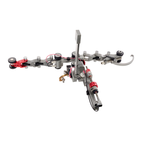
Chapter 2 CONFIGURATIONS 2.1. Nozzle Scanner - Nozzle scanner configuration Fig. 19 - Nozzle scanner configuration Fig. 20 Rev. CE0160 Rev 00 PAGE 7 of 40... -
Page 13: Operation
- Assemble configuration Fig. 22 Determine the diameter of the nozzle to be scanned. Included in the ROTIX kit is a setup chart which will indicate the number of links required based on the diameter of the pipe or tubing (Fig. - Page 14 On a flat surface, connect the appropriate amount of links as indicated on the ROTIX setup chart. Arrange the link setup so the buckle and catch link will be 180° opposite of the low profile link (Fig. 24) TIP: Place the dovetail link 2 in the chain behind the low profile link (Fig.
- Page 15 Rotate the knob until the buckle’s lever can be pushed down locking the buckle in place (Fig. 26-3) The tightness of the ROTIX on the pipe can be adjusted using the buckle adjustment knob (Fig. 26-A) TIP: If additional clearance is - Adjust pressure of buckle Fig.
- Page 16 - Lower probe holder to scan surface Fig. 28 Pull the probe holder latch pin to release the probe holder from the (Fig. 28-A) locked position (see Latch Pin on page 20 for more information) Lower the probe to the scan surface (see Encoded Skew Vertical Probe Holder Adjustment on page 19).
-
Page 17: Using A Slider Probe Positioning System
3.2. Using a Slider Probe Positioning System (Slider PPS) To setup and install a slider probe positioning system (see Slider PPS on page 23). Ensure the slider lock knob (Fig. 30-A) is tight and rotate the main knob to position the slider (Fig. -
Page 18: System Components
Chapter 4 SYSTEM COMPONENTS 4.1. Low Profile Link - ROTIX - Low profile link Fig. 31 The low profile link contains the main positional encoder and a mounting point for a frame bar. Two encoder inputs are located at the rear of the link along with the output to the user’s instrument... -
Page 19: Frame Bar Attachment
4.1.2. Frame Bar Attachment Rotate the two knobs at the front of the low profile link to align the dovetail jaws (Fig. 33). - Attach frame bar to dovetail Fig. 33 - Attach frame bar to dovetail - Tighten knobs Fig. -
Page 20: Encoder Connections
4.1.3. Encoder Connections Labled ENC 1, the Y-axis encoder plugs (slider probe positioning system) into this terminal. Labled ENC 2, plug the cable from the skew encoder here. The main output of all encoder singals, including the low profile link’s positional encoder, to the user’s instrument. -
Page 21: Encoded Skew Vertical Probe Holder
Encoded Skew Vertical Probe Holder 4.2.1. Probe Holder Adjustment Knob Probe Holder Arms Pivot Buttons Encoder Cable Skew Adjustment Indicator Ratchet Lever Latch Pin Cable Clip Probe Holder Arm Adjustment Knob - Encoded skew vertical probe holder identification Fig. 41 PAGE 16 of 40... -
Page 22: Probe Holder Setup
4.2.2. Probe Holder Setup Using the supplied 3/8 in wrench install (Fig. 2), the appropirate pivot buttons to the probe holder arms (Fig. 42) - Attach pivot buttons Fig. 42 - Mount to slider pps - Mount to slider pps Fig. - Page 23 To mount a UT wedge in the probe holder, follow these steps: - Loosen knobs and move arms - Align probe Fig. 45 Fig. 46 Loosen the two probe holder arm adjustment knobs and move the arms apart to create space for the probe (Fig.
-
Page 24: Encoded Skew Vertical Probe Holder Adjustment
- Clamp probe with arms and tighten knobs Fig. 48 Route the skew encoder cable through any required cable clips (Fig. 48). Plug the skew encoder cable into ENC 2 at the rear of the low profile link (Fig. 48) 4.2.3. - Page 25 Pull the latch pin (Fig. 50) and slowly lower the probe holder to the scan surface (Fig. 51) TIP: The probe holder must be lifted slightly to pull and release the latch pin. - Loosen knobs and move arms Fig. 51 4.2.3.3 Latch Pin The latch pin may be used in one of two methods:...
-
Page 26: Skew Angle Adjustment
4.2.4. Skew Angle Adjustment Rotation of the probe holder is possible through adjustment of the skew angle. - Loosen ratchet lever - Adjust skew angle Fig. 54 Fig. 55 Loosen the ratchet lever above the yoke (Fig. 54) Rotate the yoke to the angle required (Up to 90°... -
Page 27: Pivot Buttons
Fig. 57 Fig. 58 Fig. 59 The rachet levers are used for various locking functions on the ROTIX system. Occasionally, movement of the lever locking position is required. The lever placement can be adjusted by following these steps: Pull the ratchet lever away from the base of which it is connected (Fig. -
Page 28: Slider Pps
4.3. Slider PPS (Slider Probe Positioning System) The slider PPS uses a slide and leadscrew system to manipulate a probes position along a frame bar. To setup and install a slider PPS follow these steps: - Place slider on frame bar and loosen slider lock knob Fig. - Page 29 - Insert leadscrew into main knob and slider Fig. 63 Rotate the leadscrew to insert into the main knob and slider (Fig. 63) - Tighten screws Fig. 64 Position the slider and main knob where required along the frame bar. Tighten the the main knob’s hexagonal screw and lock screw as well as tighten the slider lock knob (Fig.
-
Page 30: Slider Pps Encoder
4.3.1. Slider PPS Encoder The slider PPS encoder is used to provide positional (probe positioning system) feedback perpendicular to the scan direction of travel. Follow these steps for installation: - Loosen and slide post in place - Align and mount post Fig. -
Page 31: Chain Components
4.4. Chain Components The chain components are used to fasten a nozzle scanning system circumferentially around a pipe or tube. - Short link - Short link with dovetail - Catch link Fig. 68 Fig. 70 Fig. 69 - Buckle - Long link Fig. -
Page 32: Cable Management System
4.5. Cable Management System - Cable management Fig. 76 TIP: When using the cable management, ensure the dovetail link is placed 2 in the chain behind the low profile link. 4.5.1. Cable Management Dovetail Mount To attach the cable management, follow these steps: - Loosen and slide on - Tighten knob Fig. -
Page 33: Cable Management Setup
4.5.2. Cable Management Setup Cable management is available in a variety of lengths and provides a means of bundling and protecting cables and hoses that run to a scanner. - Insert cables and hoses - Zip up to close Fig. 79 Fig. -
Page 34: Clamp Setup
4.5.3. Clamp Setup If the tube becomes disconnected from the cable management dovetail mount, follow these instructions to re-attach the tube and dovetail mount. Loosen the clamp screw using the supplied 3 mm hex driver. - Slide tube around mount Fig. -
Page 35: Cable Clip
4.6. Cable Clip Cable clips have been provided to assist with cable management. Simply pinch the clip and press it into the dovetail groove of the frame bar or the probe holder. - Pinch clip Fig. 86 - Cable clip - Route cables Fig. -
Page 36: Service And Support
Electronic Equipment (WEEE), this symbol indicated that the product must not be disposed of as unsorted municipal waste, but should be collected separately. Refer to Jireh Industries for return and/or collection systems available in your country. Rev. CE0160 Rev 00... -
Page 37: Spare Parts
Chapter 6 SPARE PARTS To order accessories or replacement parts for your ROTIX system. (contact Jireh Industries Ltd. on page i) NOTE: These drawings are for parts order. This is not a list of kit contents. 6.1. Low Profile Link... -
Page 38: Kit Components
6.2. Kit Components - Kit contents Fig. 90 BOM ID Part # Description CES002 Short Link Rev. CE0160 Rev 00 PAGE 33 of 40 EA470 Wrench UMA036-X-05 J400 Encoder Cable, 5 m (16.4 ft) (see Encoder Connector Type) -
Page 39: Encoder Connector Type
(0.20 Conical Head Internal Zetec PA/TOFD EA470 Wrench UMA036-X-05 J400 Encoder Cable, 5 m (16.4 ft) (see Encoder Connector Type) CEG039 Rotix - Nozzle Spare Parts Kit Part # Length Part # Length EA414 Hex Driver (1.97 (3.94 BG0038-05 BG0038-10... -
Page 40: Probe Positioning
TD - Focus Scan, Handy Scan, Pocket Scan Pragma PAUT 16/128, PragmaLite / Pragma UT400 - Slider probe positioning system parts Fig. 93 NOTE: Additional leadscrew lengths available. (contact Jireh Industries Ltd. on page i) Length Swing Arm Style Part #... -
Page 41: Encoded Skew Vertical Probe Holder
6.3. Encoded Skew Vertical Probe Holder BOM ID Part # Description BG0091 Cable Clip PH0082 Knurled Knob, M4 x 0.7 x 10 , SST, 3 mm stand off, PH0011-X see Pivot Button Style PH0237 Nozzle, Extra Short Arm Style: PHS069 Encoded Skew Vertical Probe Holder Subassembly PHS068 Encoded Skew Vertical Probe Holder Slide... -
Page 42: Probe Holder Components
NOTE: Additional probe holder pivot button types available. Part # Length Part # Length TD - Focus Scan, Handy Scan, Pocket Scan Pragma PAUT 16/128, PragmaLite / Pragma UT400 (contact Jireh Industries Ltd. on page i) (1.97 (3.94 BG0038-05 BG0038-10 BG0038-15 (5.91 BG0038-20 (7.87... -
Page 43: Accessories
6.6. Accessories 6.6.1. Cable Management BOM ID Part # Description CES067 Cable Management Mount CES066 Cable Management Clamp see Cable Management Length - Cable management Fig. 98 6.6.1.1 Cable Management Length Part # Length CX0141 4.5 m (14.7 ft) CX0145 9.5 m (31.1 ft) - Cable management length Fig. -
Page 44: Limited Warranty
THREE (3) YEARS from the original date of purchase. If a defect exists, at its option Jireh will (1) repair the product at no charge, using new or refurbished replacement parts, (2) exchange the product with a product... - Page 45 Changes or modifications to this unit or accessories, not expressly approved by the party responsible for compliance could void the user’s authority to operate the equipment. All specifications are subject to change without notice. © 2017 Jireh Industries Ltd. PAGE 40 of 40...
- Page 46 Jireh Industries Ltd. 53158 Range Road 224 Ardrossan, Alberta Canada T8E 2k4 780-922-4534 jireh.com...
Need help?
Do you have a question about the ROTIX and is the answer not in the manual?
Questions and answers