Table of Contents
Advertisement
Quick Links
Advertisement
Table of Contents

Related Manuals for Jireh ROTIX


Summary of Contents for Jireh ROTIX
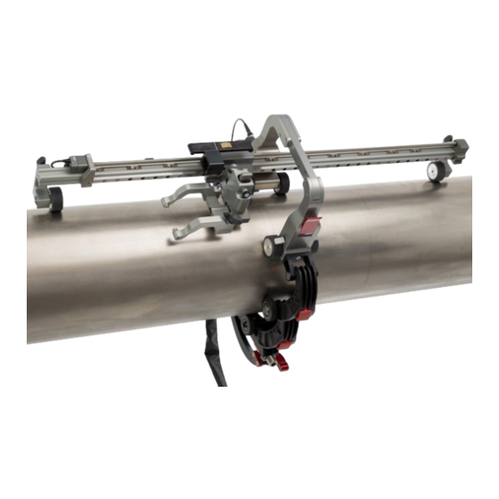
- Page 1 ROTIX CE0203 Rev 00 Reduced Width Chain Scanner...
- Page 2 SAFETY WARNINGS / PRECAUTIONS KEEP THIS MANUAL – DO NOT LOSE THIS MANUAL IS PART OF THE ROTIX AND MUST BE RETAINED FOR THE LIFE OF THE PRODUCT. PASS ON TO SUBSEQUENT OWNERS. Ensure any amendments are incorporated with this document.
-
Page 3: Table Of Contents
2.4. Performance Specifications Definitions Chapter 3.1. Definition of symbols 3.2. Definitions of Terms System Components Chapter 4.1. Base System Components 4.1.1. Reduced Width ROTIX Link 4.1.2. Frame Bar 4.1.3. Vertical Probe Holder 4.1.4. QuickLink Components 4.1.4.1 QuickLink 4.1.4.2 Dovetail QuickLink 4.1.4.3 QuickLink Buckle 4.1.4.4 QuickLink Mounting Bracket 4.1.5. Irrigation Kit 4.1.6. Tools 4.1.7. Case... - Page 4 5.6.3. Clamp Setup 5.7. Magnetic Wheel Kit 5.8. Preamp Bracket 5.8.1. Mounting Preamp Bracket 5.8.2. Attaching Preamp with Screws 5.8.3. Attaching Preamp with Velcro Straps Operation Chapter 6.1. Setup of ROTIX on a Scanning Surface Maintenance Chapter CE0203 Rev 00 PAGE iii of iv...
- Page 5 Troubleshooting Chapter 8.1. Technical Support Service and Repair Chapter Spare Parts Chapter 10.1. Kit Components 10.1.1. Encoder Connector Type 10.2. Accessories 10.2.1. Cable Management 10.2.1.1 Cable Management Sleeving 10.2.2. Preamp Bracket 10.2.3. Magnetic Wheel Kit 10.3. Vertical Probe Holder Parts 10.4. Probe Holder Components 10.4.1. Arm Style 10.4.2. Yoke Style 10.4.3. Pivot Button Style 10.5.
-
Page 6: Product Information
Chapter 1 IDENTIFICATION 1.1. Product Information The manually operated ROTIX reduced width chain scanner provides encoded probe positions of one or two probes while requiring a minimal footprint. 1.2. Manufacturer Distributor: Manufacturer: Jireh Industries Ltd. 53158 Range Road 224 Ardrossan, Alberta, Canada T8E 2K4 780.922.4534... -
Page 7: Product Specifications
(38 in) circumferential pipe/tube range Scanner Radial Clearance 9 cm (3.5 in) 2.1.2. Operating environment The ROTIX chain scanner is designed for use in an industrial environment that is between -20° C and 50° C (-4° (122° 2.2. Dimensions and Weight - Single probe dimensions Fig. - Page 8 - Two probe dimensions Fig. 2 A: Link width 10 cm (3.9 in) Link depth 24.1 cm (9.5 in) C: Link height 12 cm (4.7 in) D: Link width 25 cm (9.8 in) Link Weight* 0.64 kg (1.4 lb) Encoder Cable Length** (16.4 ft) * Link weight does not include cabling, frame bar or probe holder(s).
-
Page 9: Environmental Sealing
2.3. Environmental Sealing Watertight (submersible) (contact Jireh Industries Ltd. on page 1 for additional details) 2.4. Performance Specifications Category Specification X-Axis encoder resolution 16.3 counts/mm (414.5 counts/inch) PAGE 4 of 45... -
Page 10: Definitions
Chapter 3 DEFINITIONS 3.1. Definition of symbols Instructions to ‘look here’ or to ‘see this part.’ Denotes movement. Instructing the user to carry out an action in a specified direction. Indicates alignment axis, can also indicate insertion or movement of parts. Alerts user that the view has changed to a reverse angle. -
Page 11: System Components
Chapter 4 SYSTEM COMPONENTS 4.1. Base System Components 4.1.1. Reduced Width ROTIX Link CES104- This link reduces the scanner footprint requiring less insulation or coating to be removed from the pipe. Mount one or two probes and track positional information with the built-in encoder (Fig. -
Page 12: Quicklink Components
4.1.4. QuickLink Components The QuickLink components fasten a ROTIX system circumferentially around a pipe or tube. 4.1.4.1 QuickLink ESS004 QuickLinks connect to assemble the required length to mount the system on a pipe (Fig. 7) - QuickLink Fig. 7 4.1.4.2 Dovetail QuickLink... -
Page 13: Quicklink Mounting Bracket
4.1.4.4 QuickLink Mounting Bracket CES096 The QuickLink Mounting Bracket attaches to a frame bar and provides a connection point for QuickLinks (Fig. 10) - QuickLink Mounting Bracket Fig. 10 4.1.5. Irrigation Kit CMG007 The irrigation kit provides a variety of hoses, fittings, connectors, and splitters commonly used during non-destructive inspection (Fig. -
Page 14: Compatible Components
4.2. Compatible Components 4.2.1. Frame Bar BG0038- Frame bars are used to mount probe holders, probe positioning systems and other accessories. Frame bars are available in a variety of lengths (Fig. 12). - Frame bar Fig. 12 4.2.2. Encoder Adapter UMA010- Adapt a scanner’s existing encoder connector to a different encoder... -
Page 15: Tools
Fig. 15 Fig. 16 The 3 mm hex driver is sufficient for all typical operations and adjustments (Fig. 15) of the ROTIX. The 3/8 in wrench removes and installs pivot buttons on the (Fig. 16) probe holders. 4.3.2. Optional tools Some specialized adjustments require tools that are not included in this kit. -
Page 16: Preparation For Use
Chapter 5 PREPARATION FOR USE 5.1. Configurations 5.1.1. Single Probe Scanning - Single probe scanning Fig. 18 5.1.2. Two Probe Scanning - Two probe scanning Fig. 19 CE0203 Rev 00 PAGE 11 of 45... -
Page 17: Reduced Width Link Setup And Adjustment
5.2. Reduced Width Link Setup And Adjustment 5.2.1. Attach a Frame Bar To attach a frame bar to the reduced width link, follow these steps: - Loosen wing knobs and attach a frame bar Fig. 20 Loosen the black wing knobs counterclockwise (Fig. -
Page 18: Wheel Removal/Installation
3. Position the frame bar where required and tighten the black wing knobs (Fig. 22) - Tighten wing knobs Fig. 22 5.2.2. Wheel Removal/Installation By hand, tightly grip the wheel to be removed. Using the supplied 3 mm hex driver , loosen (Fig. -
Page 19: Connecting Quicklinks & Dovetail Links
5.3. Connecting QuickLinks & Dovetail Links 5.3.1. Connecting QuickLinks To connect QuickLinks, see the following steps: - Lift the hook over the axle of the QuickLink - Pull the link backwards to secure catch Fig. 25 Fig. 26 Lift the hook of the QuickLink over the axle of the QuickLink that is to be connected (Fig. -
Page 20: Disconnecting The Dovetail Quicklink
5.3.3. Disconnecting the Dovetail QuickLink To disconnect Dovetail QuickLinks, see the following steps: - Press red button - Slide Dovetail QuickLink forward and lift Fig. 29 Fig. 30 Press the button on the side of the Dovetail QuickLink (Fig. 29) 2. -
Page 21: Vertical Probe Holder
5.4. Vertical Probe Holder Latch Probe Holder Adjustment Knob Vertical Adjustment Knob Pivot Buttons Probe Holder Arms Yoke Probe Holder Arm Adjustment Knob Transverse Adjustment Screw Frame Bar - Vertical probe holder Fig. 31 5.4.1. Probe Holder Setup To mount a UT wedge in the probe holder, follow these steps: - Adjust on frame bar - Vertical adjustment - Place buttons... -
Page 22: Probe Holder Vertical Adjustment
- Adjust inner arm - Adjust outer arm - Tighten arm knob Fig. 35 Fig. 36 Fig. 37 4. Position the wedge on the inner probe holder arm. TIP: The probe holder yoke can accommodate many different probe and wedge sizes of varying widths. -
Page 23: Probe Holder Transverse Adjustment
Ensure the probe holder is in the latched upper position. Lift the probe holder until the latch is fully exposed and snaps out to lock (Fig. 38) 2. Loosen the vertical adjustment knob and slide the probe holder down until the wedge is approximately 6 mm (¼... -
Page 24: Probe Holder Longitudinal Adjustment
Ensure the probe holder is in latched, upper position (Fig. 38) 2. Using the supplied 3 mm hex driver loosen the transverse adjustment screw and rotate the yoke about the vertical shaft achieving the desired (Fig. 42) angle. 3. Tighten the transverse adjustment screw (Fig. -
Page 25: Probe Holder Left/Right Conversion
5.4.5. Probe Holder Left/Right Conversion To reverse the probe holder, follow these steps: NOTE: To perform this operation, the 1.5 mm hex wrench (Fig. 17) is required. - Unscrew yoke pivot screw - Remove probe holder arms Fig. 48 Fig. 49 Ensure the probe holder is in latched, upper position (Fig. - Page 26 - Screw yoke to opposite side - Lower 90° stop post Fig. 52 Fig. 53 6. Mount the yoke to the opposite side of the base using the supplied 3 mm hex driver (Fig. 52) TIP: Keep the yoke level with the base to ensure no conflicts with the plunger/set screw attached to the yoke.
-
Page 27: Pivot Buttons
5.5. Pivot Buttons Available in various shapes and sizes, fitting different wedge dimensions (see Pivot Button Style on page 40) Use the supplied 3/8 in wrench (Fig. 16) to remove and install pivot buttons (Fig. 56) - Pivot buttons Fig. 56 5.6. -
Page 28: Cable Management Dovetail Mount
5.6.1. Cable Management Dovetail Mount To attach cable management, follow these steps: - Loosen and slide on - Tighten knob Fig. 58 Fig. 59 Loosen the knob on the cable management dovetail mount. Position the mount onto the Dovetail QuickLink (Fig. -
Page 29: Clamp Setup
- Zip opposite end - Flexibility Fig. 62 Fig. 63 3. Once the cable is placed the entire length of the tube, bring the zipper from the tube’s opposite end, meeting at any point in the middle (Fig. 62) 4. When necessary, the two zippers may be opened to allow cables to exit the tube anywhere between the ends (Fig. -
Page 30: Magnetic Wheel Kit
When using a chain scanner is not appropriate, the magnetic wheel kit (Fig. 67) replace the non-magnetic wheels on a ROTIX scanner body. Two sets of the magnetic wheel kits can also be used on the scanner body to double the magnetic force. -
Page 31: Preamp Bracket
5.8. Preamp Bracket Compatible with most standard preamps, use screws or the optional velcro straps to attach a preamp to the preamp bracket. Intended Use The preamp bracket is intended to mount objects that: (e.g. preamps, splitters, etc.) ► have a maximum weight of 1.36 kg (3 lb) ►... -
Page 32: Attaching Preamp With Velcro Straps
5.8.3. Attaching Preamp with Velcro Straps To attach the preamp to the bracket using velcro straps , follow (sold separately these steps: - Insert velcro straps Fig. 71 Slide the velcro strap through the bracket’s holes (Fig. 71) 2. Centre and place the preamp on the bracket wrapping the velcro around the preamp (Fig. -
Page 33: Operation
Chapter 6 OPERATION 6.1. Setup of ROTIX on a Scanning Surface 1. Determine the diameter of the pipe or tube to be scanned. Included in the ROTIX kit and this manual is a setup chart indicating the number of links... - Page 34 4. On a flat surface, connect the appropriate number of links (see Vertical Probe Holder on page 16) indicated on the ROTIX setup chart. Arrange the link setup so the buckle and catch link will be 180° opposite the scanner body (Fig.
- Page 35 QuickLink. - Hook QuickLink Buckle to QuickLink Fig. 79 7. The tightness of the ROTIX on the pipe can be adjusted using the QuickLink Buckle adjustment knob (Fig. 80-1) - Adjust pressure of QuickLink Buckle Fig.
- Page 36 - Configured four probe configuration Fig. 82 9. Route all cabling and hoses to the cable management (Only encoder cable shown) (see Cable Management System on page 22) 10. Lower probe holders to the scan surface (see Vertical Probe Holder on page 16) CE0203 Rev 00 PAGE 31 of 45...
-
Page 37: Maintenance
Chapter 7 MAINTENANCE General cleaning of components is important to keep your system working well. All components that have no wiring or cables are completely waterproof. Components can be washed with warm water, dish soap and a medium bristle brush. Before using the scanner, ensure all connectors are free of water and moisture. -
Page 38: Troubleshooting
The scanner is not set Reconfigure the scanner as per instructions contact. correctly. (see Setup of ROTIX on a Scanning Surface on page 28). 8.1. Technical Support For technical support, contact Jireh Industries (see “Jireh Industries Ltd.” on page 1) -
Page 39: Service And Repair
Chapter 9 SERVICE AND REPAIR WARNING! DO NOT DISASSEMBLE. No user-serviceable parts. Disassembling any of the components in this product, beyond the instructions in this user manual, could void the regulatory certifications and/or effect the safety of the product. PAGE 34 of 45... -
Page 40: Spare Parts
Chapter 10 SPARE PARTS To order accessories or replacement parts for your ROTIX system. (contact Jireh Industries Ltd. on page 1) NOTE: These drawings are for parts order. This is not a list of kit contents. 10.1. Kit Components - ROTIX parts Fig. -
Page 41: Encoder Connector Type
Zetec Z-Scan Eddyfi Ectane 2 Olympus OmniScan SX/MX2/X3 Pragma PAUT M2M MANTIS/GEKKO LEMO Sonatest Veo / Prisma - Single (Technology Design) Axis NOTE: Additional encoder connector styles are available. (contact Jireh Industries Ltd. on page 1) PAGE 36 of 45... -
Page 42: Accessories
10.2. Accessories 10.2.1. Cable Management BOM ID Part # Description CES067 Cable Management Mount, Dovetail Mount CES066 Cable Management Clamp, Dovetail Mount See Cable Management Sleeving CES044- Cable Management: Dovetail (see cable management sleeving) - Cable management Fig. 84 10.2.1.1 Cable Management Sleeving Part # Length CX0141... -
Page 43: Magnetic Wheel Kit
10.2.3. Magnetic Wheel Kit Part # Description BTG014 Magnetic Wheel Kit - Magnetic wheel kit Fig. 87 PAGE 38 of 45... -
Page 44: Vertical Probe Holder Parts
10.3. Vertical Probe Holder Parts BOM ID Part # Description PHS028 Vertical Probe Holder Subassembly MA307 Screw, M4x16 mm High Strength SST SHCS PH0087 Vertical Probe Holder Base MD050-016 SHCS, M4 x 0.7 x 16 mm, SST MA096 Screw, M3x8 mm Dog Point Set, SST MD050-010 SHCS, M4 x 0.7 x 10 mm, SST PH0082 Knurled Knob, M4 x 0.7 x 10 mm, 3 mm stand off, SST... -
Page 45: Probe Holder Components
Internal (0.106 Sonatest DAAH PA (0.375 NOTE: Additional probe holder pivot button types are available. (0.197 Zetec PA/TOFD Conical Head Internal (contact Jireh Industries Ltd. on page 1) (0.157 Part # (0.118 (0.118 Length Part # (0.09 Length Internal (0.157 (0.118... -
Page 46: Case
10.6. Case BOM ID Part # Description CEA013 ROTIX Reduced Width Case - Case Fig. 93 CE0203 Rev 00 PAGE 41 of 45... -
Page 47: Disposal
Electronic Equipment , this symbol indicates that the product (WEEE) must not be disposed of as unsorted municipal waste, but should be collected separately. Refer to Jireh Industries for return and/or collection systems available in your country. PAGE 42 of 45... -
Page 48: Limited Warranty
THREE (3) YEARS from the original date of purchase. If a defect exists, at its option Jireh will (1) repair the product at no charge, using new or refurbished replacement parts, (2) exchange the product with a product that is new... - Page 49 Changes or modifications to this unit or accessories not expressly approved by the party responsible for compliance could void the user’s authority to operate the equipment. All specifications are subject to change without notice. © 2016-2023 Jireh Industries Ltd. PAGE 44 of 45...
-
Page 50: Appendix
Chapter 13 APPENDIX 13.1. Reduced Width Chain Configuration Setup Chart PIPE OD RANGE PIPE QUICKLINKS DOVETAIL (in) (in) (mm) (mm) QUICKLINK EES011 10.3 10.3 11.5 10.3 11.5 12.6 11.5 12.6 13.7 12.6 13.7 14.8 13.7 14.8 15.9 14.8 15.9 17.0 15.9 17.0 18.3... - Page 51 Jireh Industries Ltd. 53158 Range Road 224 Ardrossan, Alberta Canada T8E 2K4 780-922-4534 jireh.com...
Need help?
Do you have a question about the ROTIX and is the answer not in the manual?
Questions and answers