Table of Contents

Related Manuals for Jireh STIX


Summary of Contents for Jireh STIX
- Page 1 BG0088 Rev 03.4 Manual Magnetic TOFD Scanner...
- Page 2 SAFETY WARNINGS / PRECAUTIONS KEEP THIS MANUAL – DO NOT LOSE THIS MANUAL IS PART OF THE STIX AND MUST BE RETAINED FOR THE LIFE OF THE PRODUCT. PASS ON TO SUBSEQUENT OWNERS. Ensure any amendments are incorporated with this document.
-
Page 3: Table Of Contents
1.3.3. Maintenance Configurations Chapter 2.1. Two Probe TOFD 2.2. Two Probe TOFD Cantilever Operation Chapter 3.1. STIX setup on a scan surface Component Overview Chapter 4.1. Handle 4.2. Wheel Block 4.2.1. Wheel Installation 4.2.2. Wheel Removal 4.2.3. Ratchet Lever 4.3. - Page 4 Service and Support Chapter 5.1. Troubleshooting 5.2. Technical Support 5.3. Disposal Spare Parts Chapter 6.1. Scanner 6.2. Kit Components 6.2.1. Encoder Connector Type 6.3. Accessories 6.3.1. Magnetic Wheel Kit 6.3.2. Pre-Amp Bracket 6.3.3. Cable Management 6.4. Probe Holders 6.4.1. Slip Joint Probe Holder Parts 6.4.2.
- Page 5 PAGE iv of iv...
-
Page 6: Introduction
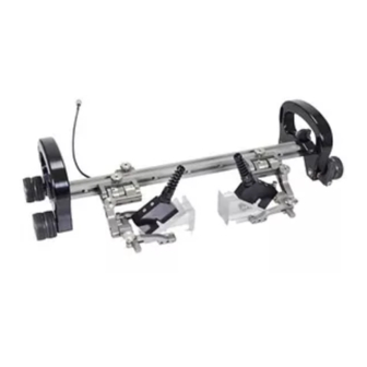
Chapter 1 INTRODUCTION 1.1. Product information 1.1.1. Intended use The STIX is a manual magnetic scanner with trailing encoder and magnetic wheels. It is designed to translate two TOFD probes around ferrous piping and vessels. 1.1.2. Performance specifications Minimum Maximum Pipe/Tube Range Outer Diameter 10.2 cm... -
Page 7: Hardware
Fig. 2 The 3 mm hex driver is sufficient for all typical operations and (Fig. 1) adjustments of the STIX. The 3/8 in wrench is used to remove and (Fig. 2) install buttons on the probe holders. 1.3.2. Optional tools Some specialized adjustments require tools that are not included with this kit. -
Page 8: Configurations
Chapter 2 CONFIGURATIONS 2.1. Two Probe TOFD - Two probe TOFD configuration Fig. 7 2.2. Two Probe TOFD Cantilever - Two probe TOFD cantilever configuration Fig. 8 BG0088 Rev 03.4 PAGE 3 of 25... -
Page 9: Operation
Chapter 3 OPERATION 3.1. STIX setup on a scan surface Mount TOFD wedges to the probe holders (see Spring Loaded Probe Holder on page 11). TIP: Mounting the wedges to the spring loaded probe holders can be easier when the probe... - Page 10 Route cables and hoses through the handle (Fig. 11) - Place on scan surface Fig. 12 Place the configured STIX on the scan surface (Fig. 12) TIP: Use caution when placing equipment on the scan surface. The magnetized wheels can cause the assembly to lurch towards the metal suddenly.
- Page 11 - Prepared for scanning Fig. 13 The spring loaded probe holders are designed to maintain wedge contact with the scan surface , as well, the encoder is designed to maintain contact (Fig. 13) pressure on the scan surface for accurate reading. Release the both brakes to begin scanning procedure.
-
Page 12: Component Overview
Chapter 4 COMPONENT OVERVIEW 4.1. Handle Used to operate the scanner as well as provide a means of cable management. To install and setup the handle, follow these steps: - Attach handle to frame bar - Tighten handle knob Fig. 14 Fig. -
Page 13: Wheel Block
4.2. Wheel Block The wheel block provides stability and braking to the STIX system. The ratchet lever located on the wheel block operates a brake (see Ratchet Lever on page 9) - Attach to frame bar - Tighten wing knob Fig. -
Page 14: Ratchet Lever
ICD’s must stay at least 25 cm away. (10 in) 4.2.3. Ratchet Lever The rachet levers lock the brakes of the STIX system. Occasionally, movement of the lever’s locking position is required. The lever placement can be adjusted by following these steps: - Pull ratchet handle... -
Page 15: Trailing Encoder
4.4. Trailing Encoder The spring loaded encoder wheel provides vertical travel while maintaining contact pressure to the scan surface. To install the encoder follow these steps: - Attach to frame bar - Place on scan surface - Tighten knob Fig. 25 Fig. -
Page 16: Spring Loaded Probe Holder
4.6. Spring Loaded Probe Holder Frame Bar Probe Holder Adjustment Knob Yoke Probe Holder Arm Adjustment Knob Probe Holder Arm Pivot Button Arm Clamp Screw - Spring loaded probe holder Fig. 29 4.6.1. Probe Holder Setup To mount a TOFD wedge in the spring loaded probe holder, follow these steps: - Position on frame bar - Attach to frame bar Fig. - Page 17 TIP: Wedge pivoting may be impeded when utilizing pivot buttons closer to the yoke. (see Pivot Buttons on page 10) - Adjust inner probe holder arm - Place wedge and outer arm Fig. 32 Fig. 33 Loosen the probe holder arm adjustment knob and remove outer (Fig.
-
Page 18: Magnetic Wheel Kit
People with pacemakers or ICD’s must stay at least 25 cm away. (10 in) Two sets of the magnetic wheels can be used with the STIX, thus doubling the magnetic force. NOTE: Magnetic wheels may lose their magnetic properties if heated above 175°... -
Page 19: Pre-Amp Bracket
4.8. Pre-Amp Bracket The pre-amp bracket mounts to any dovetail groove to hold a pre-amp. Compatible with most standard pre- amps, use the adjustable screw mounting channel on the bottom of the bracket to attach a pre-amp. The pre-amp bracket may also be ordered with velcro straps which are used to hold the pre-amp. -
Page 20: Service And Support
In accordance with European Directive on Waste Electrical and Electronic Equipment (WEEE), this symbol indicated that the product must not be disposed of as unsorted municipal waste, but should be collected separately. Refer to Jireh Industries for return and/or collection systems available in your country. BG0088 Rev 03.4... -
Page 21: Spare Parts
Chapter 6 SPARE PARTS To order accessories or replacement parts for your STIX system. (contact Jireh Industries Ltd. on page i) NOTE: These drawings are for parts order. This is not a list of kit contents. 6.1. Scanner BOM ID Part #... -
Page 22: Kit Components
Loom Installation Tool CTL-SP040-1.5 Cable Sleeving CMG007 Irrigation Kit, 2-4 Probe PHG014 2 Probe Spare Parts Kit BGS053-X Trailing Encoder (see Encoder Connector Type) EA414 Hex Driver EA470 Wrench - Stix kit components Fig. 41 BG0088 Rev 03.4 PAGE 17 of 25... -
Page 23: Encoder Connector Type
Fig. 42 Length Swing Arm Style Part # Length Swing Arm Style Part # NOTE: Additional encoder connector styles available. (contact Jireh Industries Ltd. on page i) Short PH0069 Long PH0100 (1.61 (1.81 6.3. Accessories 6.3.1. Magnetic Wheel Kit Part #... -
Page 24: Cable Management
6.3.3. Cable Management BOM ID Part # Description CES067 Zipper Tube Mount CES066 Zipper Tube Clamp (see Cable Management Length) - Cable management Fig. 45 6.3.3.1 Cable Management Length Part # Length 4.5 m CX0141 (14.7 ft) CX0145 9.5 m (31.1 ft) - Cable management length Fig. -
Page 25: Probe Holders
6.4. Probe Holders 6.4.1. Slip Joint Probe Holder Parts BOM ID Part # Description PHS022 Slip Joint Probe Holder Subassembly MD050-010 SHCS, M4 x 0.7 x 10 mm, SST PH0104 Knob, M4 x 0.7 x 18 mm, 4 mm stand off, SST PH0100 (see Swing Arm Style) PH0082... -
Page 26: Vertical Probe Holder Parts
6.4.2. Vertical Probe Holder Parts BOM ID Part # Description PHS028 Vertical Probe Holder Subassembly PH0082 Knob, M4 x 0.7 x 10 mm, 3 mm stand off, SST PH00XX (see Slip Joint and Vertical Probe Holder Arm Style) PH0011-X (see Pivot Button Style) PHS0XX (see Slip Joint and Vertical Probe Holder Yoke Style) MD050-010 SHCS, M4 x 0.7 x 10 mm, SST... -
Page 27: Probe Holder Components
Yoke Style Length Yoke Style Part # Length Part # Standard PHS048 Wide PHS047 12.2 (3.26 (4.79 6.5. Probe Holder Components Pivot Hole Size Wedge Type Pivot Hole Size Wedge Type (0.32 Olympus PA (0.20 Olympus TOFD 6.5.1. Spring Loaded Arm Style (0.11 Sonatest DAAH PA (0.38... -
Page 28: Pivot Button Style
Olympus PA (0.32 (0.20 Olympus TOFD NOTE: Additional probe holder pivot button types available. Part # Length Part # Length (0.11 (contact Jireh Industries Ltd. on page i) Sonatest DAAH PA (0.38 (1.97 (3.94 BG0038-05 BG0038-10 (0.12 (0.09 BG0038-15 (5.91 BG0038-20 (7.87... -
Page 29: Limited Warranty
THREE (3) YEARS from the original date of purchase. If a defect exists, at its option Jireh will (1) repair the product at no charge, using new or refurbished replacement parts, (2) exchange the product with a product that is new... - Page 30 Changes or modifications to this unit or accessories, not expressly approved by the party responsible for compliance could void the user’s authority to operate the equipment. All specifications are subject to change without notice. © 2016 Jireh Industries Ltd. BG0088 Rev 03.4 PAGE 25 of 25...
- Page 31 Jireh Industries Ltd. 53158 Range Road 224 Ardrossan, Alberta Canada T8E 2k4 780-922-4534 jireh-industries.com...
Need help?
Do you have a question about the STIX and is the answer not in the manual?
Questions and answers